EP0621120B1 - Appareil pour onduler des tubes en matière plastique et blocs de moulage - Google Patents
Appareil pour onduler des tubes en matière plastique et blocs de moulage Download PDFInfo
- Publication number
- EP0621120B1 EP0621120B1 EP94302657A EP94302657A EP0621120B1 EP 0621120 B1 EP0621120 B1 EP 0621120B1 EP 94302657 A EP94302657 A EP 94302657A EP 94302657 A EP94302657 A EP 94302657A EP 0621120 B1 EP0621120 B1 EP 0621120B1
- Authority
- EP
- European Patent Office
- Prior art keywords
- mold
- drive
- machine
- shuttle
- path
- Prior art date
- Legal status (The legal status is an assumption and is not a legal conclusion. Google has not performed a legal analysis and makes no representation as to the accuracy of the status listed.)
- Expired - Lifetime
Links
- 239000004033 plastic Substances 0.000 title claims description 4
- 229920003023 plastic Polymers 0.000 title claims description 4
- 238000000465 moulding Methods 0.000 claims description 47
- 241000282472 Canis lupus familiaris Species 0.000 claims description 18
- 238000013459 approach Methods 0.000 claims description 6
- 239000002991 molded plastic Substances 0.000 claims description 2
- 230000001419 dependent effect Effects 0.000 claims 2
- 239000000498 cooling water Substances 0.000 description 28
- XLYOFNOQVPJJNP-UHFFFAOYSA-N water Substances O XLYOFNOQVPJJNP-UHFFFAOYSA-N 0.000 description 16
- 230000008901 benefit Effects 0.000 description 6
- 229920001169 thermoplastic Polymers 0.000 description 5
- 239000004416 thermosoftening plastic Substances 0.000 description 5
- 238000001816 cooling Methods 0.000 description 4
- 238000004519 manufacturing process Methods 0.000 description 4
- 238000000034 method Methods 0.000 description 4
- 238000007789 sealing Methods 0.000 description 4
- 239000012815 thermoplastic material Substances 0.000 description 4
- 239000000463 material Substances 0.000 description 3
- 239000004677 Nylon Substances 0.000 description 2
- 229920001778 nylon Polymers 0.000 description 2
- 230000008569 process Effects 0.000 description 2
- 229920000114 Corrugated plastic Polymers 0.000 description 1
- 239000000853 adhesive Substances 0.000 description 1
- 230000001070 adhesive effect Effects 0.000 description 1
- 230000015556 catabolic process Effects 0.000 description 1
- 230000008859 change Effects 0.000 description 1
- 238000004891 communication Methods 0.000 description 1
- 230000006835 compression Effects 0.000 description 1
- 238000007906 compression Methods 0.000 description 1
- 238000006731 degradation reaction Methods 0.000 description 1
- 230000000593 degrading effect Effects 0.000 description 1
- 230000009977 dual effect Effects 0.000 description 1
- 230000001939 inductive effect Effects 0.000 description 1
- 238000009434 installation Methods 0.000 description 1
- 230000003993 interaction Effects 0.000 description 1
- 230000013011 mating Effects 0.000 description 1
- 238000013021 overheating Methods 0.000 description 1
- 238000005096 rolling process Methods 0.000 description 1
- 230000001360 synchronised effect Effects 0.000 description 1
- 230000007704 transition Effects 0.000 description 1
Images




Classifications
-
- B—PERFORMING OPERATIONS; TRANSPORTING
- B29—WORKING OF PLASTICS; WORKING OF SUBSTANCES IN A PLASTIC STATE IN GENERAL
- B29C—SHAPING OR JOINING OF PLASTICS; SHAPING OF MATERIAL IN A PLASTIC STATE, NOT OTHERWISE PROVIDED FOR; AFTER-TREATMENT OF THE SHAPED PRODUCTS, e.g. REPAIRING
- B29C49/00—Blow-moulding, i.e. blowing a preform or parison to a desired shape within a mould; Apparatus therefor
- B29C49/0015—Making articles of indefinite length, e.g. corrugated tubes
- B29C49/0021—Making articles of indefinite length, e.g. corrugated tubes using moulds or mould parts movable in a closed path, e.g. mounted on movable endless supports
-
- B—PERFORMING OPERATIONS; TRANSPORTING
- B29—WORKING OF PLASTICS; WORKING OF SUBSTANCES IN A PLASTIC STATE IN GENERAL
- B29C—SHAPING OR JOINING OF PLASTICS; SHAPING OF MATERIAL IN A PLASTIC STATE, NOT OTHERWISE PROVIDED FOR; AFTER-TREATMENT OF THE SHAPED PRODUCTS, e.g. REPAIRING
- B29C48/00—Extrusion moulding, i.e. expressing the moulding material through a die or nozzle which imparts the desired form; Apparatus therefor
- B29C48/25—Component parts, details or accessories; Auxiliary operations
- B29C48/252—Drive or actuation means; Transmission means; Screw supporting means
- B29C48/2528—Drive or actuation means for non-plasticising purposes, e.g. dosing unit
-
- B—PERFORMING OPERATIONS; TRANSPORTING
- B29—WORKING OF PLASTICS; WORKING OF SUBSTANCES IN A PLASTIC STATE IN GENERAL
- B29C—SHAPING OR JOINING OF PLASTICS; SHAPING OF MATERIAL IN A PLASTIC STATE, NOT OTHERWISE PROVIDED FOR; AFTER-TREATMENT OF THE SHAPED PRODUCTS, e.g. REPAIRING
- B29C48/00—Extrusion moulding, i.e. expressing the moulding material through a die or nozzle which imparts the desired form; Apparatus therefor
- B29C48/25—Component parts, details or accessories; Auxiliary operations
- B29C48/256—Exchangeable extruder parts
- B29C48/2566—Die parts
-
- B—PERFORMING OPERATIONS; TRANSPORTING
- B29—WORKING OF PLASTICS; WORKING OF SUBSTANCES IN A PLASTIC STATE IN GENERAL
- B29C—SHAPING OR JOINING OF PLASTICS; SHAPING OF MATERIAL IN A PLASTIC STATE, NOT OTHERWISE PROVIDED FOR; AFTER-TREATMENT OF THE SHAPED PRODUCTS, e.g. REPAIRING
- B29C48/00—Extrusion moulding, i.e. expressing the moulding material through a die or nozzle which imparts the desired form; Apparatus therefor
- B29C48/25—Component parts, details or accessories; Auxiliary operations
- B29C48/30—Extrusion nozzles or dies
- B29C48/3001—Extrusion nozzles or dies characterised by the material or their manufacturing process
-
- B—PERFORMING OPERATIONS; TRANSPORTING
- B29—WORKING OF PLASTICS; WORKING OF SUBSTANCES IN A PLASTIC STATE IN GENERAL
- B29C—SHAPING OR JOINING OF PLASTICS; SHAPING OF MATERIAL IN A PLASTIC STATE, NOT OTHERWISE PROVIDED FOR; AFTER-TREATMENT OF THE SHAPED PRODUCTS, e.g. REPAIRING
- B29C48/00—Extrusion moulding, i.e. expressing the moulding material through a die or nozzle which imparts the desired form; Apparatus therefor
- B29C48/25—Component parts, details or accessories; Auxiliary operations
- B29C48/30—Extrusion nozzles or dies
- B29C48/303—Extrusion nozzles or dies using dies or die parts movable in a closed circuit, e.g. mounted on movable endless support
-
- B—PERFORMING OPERATIONS; TRANSPORTING
- B29—WORKING OF PLASTICS; WORKING OF SUBSTANCES IN A PLASTIC STATE IN GENERAL
- B29C—SHAPING OR JOINING OF PLASTICS; SHAPING OF MATERIAL IN A PLASTIC STATE, NOT OTHERWISE PROVIDED FOR; AFTER-TREATMENT OF THE SHAPED PRODUCTS, e.g. REPAIRING
- B29C49/00—Blow-moulding, i.e. blowing a preform or parison to a desired shape within a mould; Apparatus therefor
- B29C49/28—Blow-moulding apparatus
- B29C49/30—Blow-moulding apparatus having movable moulds or mould parts
- B29C49/38—Blow-moulding apparatus having movable moulds or mould parts mounted on movable endless supports
-
- B—PERFORMING OPERATIONS; TRANSPORTING
- B29—WORKING OF PLASTICS; WORKING OF SUBSTANCES IN A PLASTIC STATE IN GENERAL
- B29C—SHAPING OR JOINING OF PLASTICS; SHAPING OF MATERIAL IN A PLASTIC STATE, NOT OTHERWISE PROVIDED FOR; AFTER-TREATMENT OF THE SHAPED PRODUCTS, e.g. REPAIRING
- B29C35/00—Heating, cooling or curing, e.g. crosslinking or vulcanising; Apparatus therefor
- B29C35/16—Cooling
- B29C2035/1616—Cooling using liquids
-
- B—PERFORMING OPERATIONS; TRANSPORTING
- B29—WORKING OF PLASTICS; WORKING OF SUBSTANCES IN A PLASTIC STATE IN GENERAL
- B29C—SHAPING OR JOINING OF PLASTICS; SHAPING OF MATERIAL IN A PLASTIC STATE, NOT OTHERWISE PROVIDED FOR; AFTER-TREATMENT OF THE SHAPED PRODUCTS, e.g. REPAIRING
- B29C2791/00—Shaping characteristics in general
- B29C2791/004—Shaping under special conditions
- B29C2791/006—Using vacuum
-
- B—PERFORMING OPERATIONS; TRANSPORTING
- B29—WORKING OF PLASTICS; WORKING OF SUBSTANCES IN A PLASTIC STATE IN GENERAL
- B29C—SHAPING OR JOINING OF PLASTICS; SHAPING OF MATERIAL IN A PLASTIC STATE, NOT OTHERWISE PROVIDED FOR; AFTER-TREATMENT OF THE SHAPED PRODUCTS, e.g. REPAIRING
- B29C33/00—Moulds or cores; Details thereof or accessories therefor
- B29C33/02—Moulds or cores; Details thereof or accessories therefor with incorporated heating or cooling means
-
- B—PERFORMING OPERATIONS; TRANSPORTING
- B29—WORKING OF PLASTICS; WORKING OF SUBSTANCES IN A PLASTIC STATE IN GENERAL
- B29C—SHAPING OR JOINING OF PLASTICS; SHAPING OF MATERIAL IN A PLASTIC STATE, NOT OTHERWISE PROVIDED FOR; AFTER-TREATMENT OF THE SHAPED PRODUCTS, e.g. REPAIRING
- B29C33/00—Moulds or cores; Details thereof or accessories therefor
- B29C33/20—Opening, closing or clamping
- B29C33/26—Opening, closing or clamping by pivotal movement
-
- B—PERFORMING OPERATIONS; TRANSPORTING
- B29—WORKING OF PLASTICS; WORKING OF SUBSTANCES IN A PLASTIC STATE IN GENERAL
- B29C—SHAPING OR JOINING OF PLASTICS; SHAPING OF MATERIAL IN A PLASTIC STATE, NOT OTHERWISE PROVIDED FOR; AFTER-TREATMENT OF THE SHAPED PRODUCTS, e.g. REPAIRING
- B29C49/00—Blow-moulding, i.e. blowing a preform or parison to a desired shape within a mould; Apparatus therefor
- B29C49/0015—Making articles of indefinite length, e.g. corrugated tubes
- B29C49/0021—Making articles of indefinite length, e.g. corrugated tubes using moulds or mould parts movable in a closed path, e.g. mounted on movable endless supports
- B29C49/0022—Making articles of indefinite length, e.g. corrugated tubes using moulds or mould parts movable in a closed path, e.g. mounted on movable endless supports characterised by mould return means
-
- B—PERFORMING OPERATIONS; TRANSPORTING
- B29—WORKING OF PLASTICS; WORKING OF SUBSTANCES IN A PLASTIC STATE IN GENERAL
- B29C—SHAPING OR JOINING OF PLASTICS; SHAPING OF MATERIAL IN A PLASTIC STATE, NOT OTHERWISE PROVIDED FOR; AFTER-TREATMENT OF THE SHAPED PRODUCTS, e.g. REPAIRING
- B29C49/00—Blow-moulding, i.e. blowing a preform or parison to a desired shape within a mould; Apparatus therefor
- B29C49/0015—Making articles of indefinite length, e.g. corrugated tubes
- B29C49/0027—Making articles of indefinite length, e.g. corrugated tubes involving the change of moulds, e.g. in production processes without interrupting the production processes
-
- B—PERFORMING OPERATIONS; TRANSPORTING
- B29—WORKING OF PLASTICS; WORKING OF SUBSTANCES IN A PLASTIC STATE IN GENERAL
- B29C—SHAPING OR JOINING OF PLASTICS; SHAPING OF MATERIAL IN A PLASTIC STATE, NOT OTHERWISE PROVIDED FOR; AFTER-TREATMENT OF THE SHAPED PRODUCTS, e.g. REPAIRING
- B29C49/00—Blow-moulding, i.e. blowing a preform or parison to a desired shape within a mould; Apparatus therefor
- B29C49/42—Component parts, details or accessories; Auxiliary operations
- B29C49/48—Moulds
- B29C49/4823—Moulds with incorporated heating or cooling means
-
- B—PERFORMING OPERATIONS; TRANSPORTING
- B29—WORKING OF PLASTICS; WORKING OF SUBSTANCES IN A PLASTIC STATE IN GENERAL
- B29L—INDEXING SCHEME ASSOCIATED WITH SUBCLASS B29C, RELATING TO PARTICULAR ARTICLES
- B29L2023/00—Tubular articles
- B29L2023/003—Tubular articles having irregular or rough surfaces
-
- B—PERFORMING OPERATIONS; TRANSPORTING
- B29—WORKING OF PLASTICS; WORKING OF SUBSTANCES IN A PLASTIC STATE IN GENERAL
- B29L—INDEXING SCHEME ASSOCIATED WITH SUBCLASS B29C, RELATING TO PARTICULAR ARTICLES
- B29L2023/00—Tubular articles
- B29L2023/18—Pleated or corrugated hoses
Definitions
- the present invention is directed toward corrugators, and more particularly toward corrugators for making corrugated plastic tubing.
- a well known method for manufacturing corrugated pipes is to extrude a tube of thermoplastic from a head and then conform that tube to the interior of a corrugated mold tunnel formed by mold blocks.
- the mold blocks typically come in pairs and mate together to form a portion of the mold tunnel, and the thermoplastic is either blown into its shape (by pressure created within the mold tunnel) or by vacuum (where vacuum draws the air from around the mold tunnel).
- thermoplastic Conforming the thermoplastic to the larger diameter mold blocks with a uniformity of wall thickness can be difficult.
- Cooling of the larger mold blocks is also difficult.
- inadequate cooling of the mold blocks can result in improperly elevated temperatures through the molding process and degradation of the quality of the molded tubes.
- any forces incurred on the other side of the mold blocks naturally involves a larger moment arm about the carriages, with the result being that such structures can be more susceptible to "sawtooth" type arrangements through the mold tunnel, with successive mold blocks being tilted slightly rather than perfectly aligned with the axis of the mold tunnel.
- cost effectiveness of the machines making larger diameter tubes is a significant factor, since the size and cost of each mold block is significantly higher than the cost of mold blocks used to make small tubes. Since numerous such mold blocks are required to operate any machine to make a particular size tube, and since numerous sets of mold blocks are typically necessary to allow a machine to be used to make the desired different size tubes, the cost of each mold block and the number of mold blocks required to be on hand can significantly impact the cost of the machine and, therefore, the cost of the molded tubes. Further, since the cost of mold blocks is typically a significant cost which must be incurred up front (i.e. , when the machine is first purchased), its cost must be recouped over time as the tubes are made and sold. Therefore, not only does the significant cost of mold blocks alone impact the cost of molded tubes, but the cost of carrying that expense over several years before it can be recouped can also add to the cost of the molded tubes.
- the present invention is directed toward overcoming one or more of the problems set forth above.
- Another object of the present invention is to provide a corrugator which may be operated at relatively high speeds over long periods of time without degrading the quality of the produced tubing.
- the present invention provides a machine cooperating with an extruder to continuously mold plastic.
- the machine comprises a first continuous path defined on the machine and a plurality of separate mold blocks guided about the first continuous path, each of said mold blocks cooperating with another mold block along a molding section of the first continuous path to form a mold tunnel, whereby said mold blocks enter the molding section at its beginning and exit the molding section at its end.
- the machine further comprises a mold train drive driving a selected number of mold blocks at the beginning of the molding section to continuously drive the mold blocks along the molding section at a selected speed, and a shuttle drive travelling along a second continuous path which path substantially follows said first continuous path through a shuttle area and includes a portion spaced from said first path along a substantial portion of said molding section.
- First and second connecting sections are provided on the shuttle drive and are spaced from one another, each connecting section being guidably connectable to a mold block except when in the second path portion spaced from said first path.
- the machine also provides means for selectively driving said shuttle drive around said second path at the selected speed of the mold train drive when a mold block is connected to both the shuttle drive and the mold train drive, and at a speed faster than the selected speed when a connecting section is in the second path portion spaced from said first path.
- the machine may also comprise means for accelerating the shuttle drive when one of the connecting sections enters the shuttle drive portion spaced from the first continuous path; and means for decelerating the shuttle drive to the speed of the mold train drive as one of the connecting sections reaches the beginning of the molding section.
- the shuttle drive may also be substantially tangential to one side of two end gears and engage both of said end gears through more than 180°, whereby straight sections of the drive between the gears are spaced apart less than the diameter of the gears.
- encoders are provided on the shuttle drive for detecting the position of the shuttle drive, said encoders providing feedback for control of the selectively driving means.
- one of the connecting sections In one position of the shuttle drive it is desirable for one of the connecting sections to driveably connect the shuttle drive to a mold block at the beginning of the molding section and another connecting section to drivably connect the shuttle drive to a mold block at the end of the molding section.
- the mold blocks are carried by carriages.
- Each carriage may include grooves and said connecting sections may comprise dogs secured to a portion of the shuttle drive and receivable to mate with said grooves.
- the shuttle drive has an overall length L
- said first and second connecting sections are preferably spaced apart on said drive a distance of approximately 1 ⁇ 2L.
- the shuttle drive is preferably a driven chain, and more preferably, a continuously driven chain.
- the carriages each carry a pair of said cooperating mold blocks pivotable about an axis substantially aligned with the first continuous path, and for the machine to comprise means for guiding said mold blocks about their carriage pivotal axis whereby cooperating mold blocks are pivoted together at the beginning of the molding section to form a portion of the mold tunnel and are separated at the end of the molding section to release continuous molded plastic.
- the first continuous path is defined by a guide track, and said carriages have rollers following the guide track.
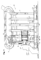
- a corrugator 20 embodying the present invention is shown in particular in Figs. 1-4.
- the corrugator 20 includes a frame 22 supported on horizontal support beams 24.
- the support beams 24 include suitable wheels 26 to permit the corrugator to be moved when needed.
- a rail structure 28, on which the wheels 26 locate, is provided with a configuration which will accommodate the size and weight of the corrugator 20.
- the corrugator 20 generally defines a continuous endless path 32 (see particularly Fig. 3) for circulating suitable corrugated mold blocks 30 to form a mold tunnel 34 through the molding section of the corrugator 20 in alignment with an extruder for thermoplastic material.
- the extruder 40 (shown somewhat schematically in Fig. 1) supplies a continuous annular sheet of thermoplastic material 42 which is drawn into the corrugated tunnel defined by the mold blocks 30 (as described in greater detail hereafter) to form the desired corrugated tube.
- Such tubes have numerous uses, with larger diameter tubes (up to four feet in diameter and more) commonly being used, for example, for drainage.
- the mold blocks 30 are suitably secured to carriages 50.
- the carriage 50 includes a carriage body 52 having two dogs 54 projecting therefrom and defining a clamshell pivot 56.
- Pivotally secured to the clamshell pivot 56 are pivotal mounting members 58 to which the mold blocks 30 are secured.
- the mounting members 58 are relatively easily removable from the clamshell pivot 56, so that different size mounting members can be used where required for different size mold blocks. That is, as will be appreciated, the central axis of the annular material 42 produced by the extruder 40 must generally correspond to the central axis 60 (see Fig. 2) of the mold tunnel 34.
- This alignment is important to producing proper tubes since misalignment can result in non-uniform tube thickness (with the material on one side thicker than that on the other side).
- an operator can readily change from one size to another without having to tediously realign the extruder 40 each time a switch in size occurs. That is, the operator merely has to mount the right mold blocks and mounting members and the mold tunnel axis 60 will naturally correspond to the axis of the extruder 40 without any possibility of misalignment. (The need for such different size mounting members is perhaps best illustrated by a comparison of the small mold blocks 30 shown in Fig. 2 to the larger mold blocks 30' shown in phantom at the top of Fig. 2).
- the carriage body 52 follows a track which suitably guides it around the oval continuous path 32.
- the mounting members 58 also include guide wheels 64 which follow clamshell guide tracks 66 to suitably pivot the mounting members 58 to open and close the mold blocks 30 as necessary. That is, the mold blocks 30 are held apart as they approach the mold tunnel 34 in order that they will be clear of the extruder 40. The blocks 30 are then closed over the extruder 40 and the annular material 42 produced thereby to form a portion of the mold tunnel 34. The blocks 30 are maintained in this mating position (shown in the bottom of Fig. 2) along the length of the mold tunnel 34. At the end of the mold tunnel 34, the mounting members 58 pivot out to separate the mold blocks 30 so that they will clear the tube formed therein. The carriage 50 then circles up around the end of the continuous path 32 and returns along the top of the path 32 to the beginning of the mold tunnel 34 as described hereafter in greater detail.
- a mold train drive 70 and a shuttle drive 72.
- the mold train drive 70 is disposed at the beginning of the mold tunnel 34 and operates at a substantially constant speed (depending on the output of the extruder 40) to relatively slowly drive the carriages 50 and associated mold blocks 30 at the beginning of the mold tunnel 34 to effectively drive all of the carriages 50 in the mold train at a constant speed.
- the shuttle drive 72 follows the carriage continuous path 32 for over half of its length, with the remaining a portion 74 of the shuttle drive 72 being spaced from the path (along a substantial portion of the length of the molding section).
- the shuttle drive 72 includes two continuous chains 76 (see Fig. 2) laterally spaced on opposite sides of the carriage 50, which chains 76 are guided by suitable idlers to follow the path shown in Fig. 3.
- Each chain 76 includes two sets of dogs 78 which are equally spaced halfway around the chain (the dogs 78 of each chain being aligned with the dogs 78 of the other chain, as the two chains 76 operate in tandem).
- the carriages 50 contain shuttle racks 80 which will engage a set of dogs 78 when along those portions of the shuttle drive 72 which follows the carriage continuous path 32.
- the shuttle drive 72 operates at a variable speed depending on its position during operation.
- the shuttle drive 72 is accelerated to bring the engaged carriage 50 (shown in the upper right of Fig. 3) back to the beginning of the mold train.
- the shuttle drive 72 decelerates gradually until it is once again operating at the same speed as the mold train drive 70 at substantially the point at which the shuttle drive engaged carriage 50 is engaged again by the mold train drive 70.
- the corrugator 20 can be operated with a minimal number of carriages 50 and mold blocks 30. Given the expense involved with both, and particularly the expense of the multiple sets of mold blocks 30 required in most installations, these savings are significant. Of course, such cost savings translate into reduced cost of the tubes formed by corrugators 20 embodying the present invention.
- each shuttle drive chain 76 it would be within the scope of the present invention to use more than two sets of dogs 78 on each shuttle drive chain 76.
- four sets of dogs could be evenly spaced about the length of each chain 76, in which case operation would be similar to that described above except that generally two carriages 50 would be shuttled, where each such shuttled carriage 50 would decelerate approximately halfway through its shuttle path to the speed of the mold train while the other shuttle is dropped off. Once the first shuttled carriage is disengaged from the shuttle drive dogs at the beginning of the mold train, the following decelerated carriage 50 would then be accelerated again for travel through the last half of its shuttle path.
- the mold train drive 70 includes a suitable drive motor 88 which rotates drive sprockets 90 (on opposite sides of the corrugator 20, laterally spaced outwardly from the shuttle drive chains 76).
- the drive sprockets 90 each drive a chain 92 having transverse pins 93 connecting two sets of laterally spaced links 94.
- the chains 92 are also driven around an idler sprocket 96 positioned so that the bottom forward path of the chains 92 is parallel to and adjacent to the carriage path 32 at the beginning of the molding section.
- the axle of the idler sprockets 92 is spring loaded in a suitable manner so as to soften the jarring which could occur in the drives 70, 72 during the transition when a shuttled carriage 50 still connected to the shuttle drive 72 is also engaged by the mold trail drive 70 at the beginning of the molding section.
- the shuttle drive 72 includes a suitable variable speed drive motor 100 capable of operating to accelerate and decelerate the shuttle drive 72 as described above.
- the shuttle drive motor 100 drives a set of drive sprockets 102 which drive the multilink shuttle drive chains 76 which, as previously described, pass around suitable idlers located along the length of the corrugator 20 so as to follow the path shown in Fig. 3.
- suitable encoders 104 can be used to count the rotations of the shuttle drive motor 100 to provide feedback as to the position of the shuttle drive 72. Since the number of links in the shuttle chains 76 and the number of sprockets on the drive sprockets 102 can be readily determined, counting the rotations of the drive sprockets 102 will provide reliable feedback in this regard.
- sensors could also be provided along the shuttle drive 72 to directly sense its position. In either event, suitable feedback can be provided to a control unit which could automatically accelerate and decelerate the shuttle drive 72 when appropriate as discussed above.
- Fig. 5 illustrates the drive engaging side of a carriage body 52.
- Shuttle racks 80 having alternating rows of grooves 110 are secured to both sides of the body 52 in lateral alignment with the shuttle drive chain 76.
- Four alternating shuttle drive dogs 78 are illustrated in Fig.5, which dogs 78 are suitably interlaced with the shuttle drive chain 76 so that they will engage the grooves 110 of the shuttle racks 80 in any shuttle chain position adjacent to the carriage path 32.
- each shuttle drive chain 76 includes only two sets of dogs 78 as previously described, the shuttle drive 70 will generally engage no more than one or two carriages 50 at any given time.
- Mold drive racks 114 are similarly secured to both sides of the body 52 outside of the shuttle racks and in lateral alignment with the mold train drive chain 92.
- Each of the mold drive racks 114 includes a series of grooves 116 which will engage the pins 93 of the mold train drive chain 92 at the beginning the molding section so as to be driven at the desired rate through the molding section (and to push the other carriages 50 forward of the mold train drive 70).
- a special carriage and track configuration for maintaining the proper alignment of the carriage body 52 is also provided and illustrated in Figs. 4 and 5.
- This structure provides significant operational advantages to prevent the mold blocks from falling into a "sawtooth" type arrangement (with successive mold blocks being tilted slightly rather than perfectly aligned with the axis of the mold tunnel) as a result of potentially significant drag forces on the bottom of the mold blocks 30 through the molding section (as will become apparent).
- the offset wheel 122 is secured to the carriage body 52 so that its lower surface (in the orientation shown in Fig. 5) is above the plane defined by the bottom surfaces of the outer wheels 120, and the upper surface of the offset wheel 122 projects above the plane defined by the upper surfaces of the outer wheels 120.
- the outer wheels 120 and offset wheel 122 are oriented so that the outer wheels 120 are both spaced laterally from the carriage body 52 beyond the offset wheel 122.
- the two outer wheels 120 follow a track 126 (shown in Fig. 4 and as ground lines in Fig. 5) only on one side (the bottom) and the offset wheel follows a track 128 (also shown in Fig. 4 and as a ground line in Fig. 5) on the opposite (top) side.
- the above guide structure for the carriages 50 results in the desired precise wobble-free movement of the carriages 50 without sawtoothing in the molding section, which operation is accomplished without requiring that expensively tight tolerances be met in the manufacture of the corrugator 20.
- the wheels 120, 122 were all aligned with their axes in a plane, it would be necessary to manufacture opposite sides of a single track to extremely tight tolerances because, if such tolerances were not met, the wheels would encounter sections in which they would bind on both sides of the track rather than freely roll therein. Requiring that the wheels 120, 122 of the carriages 50 of the present invention engage a track on only one side ensures that the wheels 120, 122 will roll freely with no worry of binding.
- the offset wheel 122 may be kept clear of the general guide track of the full carriage path 32, including the semicircular paths at each end, where precise orientation of the carriages 50 and their associated mold blocks 30 is not required, and function only in the track 128 along the molding section where such precise positioning is desirable.
- a flange 136 (see Fig. 4) projecting outwardly from the center of the continuous path 34 is preferably provided and received between pivotally mounted rollers 138 on the carriage 50 to ensure straight motion of the carriage 50 without lateral movement or twisting. This thus minimizes loading on the wheels 120, 122 to ensure smooth travel of the carriage 50 about its continuous path 32.
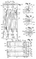
- the mold blocks 30 comprise a plurality of adjacent sub-blocks 204 adjoined so as to define a continuous corrugated surface 208 with alternating grooves 210 and lands 212 and substantially arcuate 180 degrees about the longitudinal axis 214 (see Fig. 7).
- the grooves 210 and lands 212 of each sub-block extend up to one complete wavelength (i.e., the width of one groove 210 and one land 212), so that when together, the mold block face defines a continuous corrugated surface through the mold tunnel 34.
- Adjacent sub-blocks 204 are mated at their front end face 218 and the rear end face 220, respectively.
- the sub-blocks 204 defining the mold block 30 (three such sub-blocks are shown in Figs. 7-8) are aligned by suitable dowels 224 (see Fig. 6) fitted into countersunk fastener passageways 228 of each pair of adjacent sub-blocks 204.
- Bolts 230 run coaxially through the dowels 224 the length of the mold block 30, and secure the sub-blocks 204 together by tightening of the bolts 230 and nuts 232 (the nuts and bolt heads reside in the outer fastener passageways in the end sub-blocks 204).
- a vacuum passage is defined by a suitable arrangement of grooves in the sub-blocks connected to the corrugated surface and to vacuum ports. These vacuum passages may be formed in a manner substantially similarly to those shown in U.S. Patent No. 5,059,109, the detailed disclosure of which is hereby incorporated by reference. Specifically, in the preferred embodiment, a plurality of slits 234 (one such representative slit 234 only being shown in Figs. 6 and 7) are disposed at the grooves 210 of the sub-blocks 204 and are connected to a plurality of vacuum bores 236.
- the bores 236 are in turn in communication with semicircular grooves 238 cast in the end faces 218, 220 of each sub-block 204 which, when the sub-blocks 204 are secured together as described above define a continuous circular vacuum passage.
- a similar vacuum passage is created between the adjacent mold blocks 30.
- These vacuum passages are open through ports 240 to the outside of the mold blocks 30.
- This arrangement of grooves 210 and lands 212 within each sub-block 204 permits the dedication of a vacuum passage to each groove 210 of the corrugated surface 208, thereby inducing a strong, uniform vacuum at each groove 210 of the mold tunnel 34.
- mold blocks of the present invention could also be made with semicircular grooves in only one end face of each sub-block 204.
- the interior face slits could directly communicate with the semicircular groove in the sub-block end faces, and that the semicircular grooves could be less than 180 degrees, and in fact non-connected arcuate grooves can be used with systems where more than one vacuum source is provided.
- the mold blocks of the present invention could also be practiced by using sub-blocks which are arcuate through less than 180 degrees (for example, a single large mold block could also be formed by suitably rigidly connecting together sub-blocks which are not more than one complete wavelength long but have faces curving only 90 degrees). It should be understood, however, that the disclosed structure is believed to be the preferred embodiment most suitable for common usages.
- the sub-blocks 204 further include a double groove 250 in their end faces, which grooves are connected at one end and, at their other end are connected to respective input ports 254 for cooling water and output or discharge ports 256.
- the double grooves 250 thus define cooling water passages about the mold blocks 30 to allow the blocks to be continuously used without overheating (which could degrade the quality of thermoplastic tube being made).
- a sealing groove 260 is also provided in the sub-block end faces 218, 220 surrounding the cooling water double grooves 250 on the interior faces of the sub-blocks 204.
- a suitable seal 262 (see Fig. 11), such as an elastomeric O-ring, is disposed in the sealing groove 260 so as to prevent leakage of cooling water from the interior cooling water passages.
- the double groove 250 defining the cooling water passage is preferably provided with a suitable closing in order to ensure against water leakage between adjacent mold blocks 30 in the mold train 34.
- the double groove 250 may further include recesses 270 in the side walls of the groove 250, with the flange 272 separating the double groove 250 through most of its length recessed and an annular sealing plate 274 may be slid into and suitably secured in the side wall recesses 270.
- the side wall recesses 270' may be open and the annular sealing plate 274 simply placed in the recesses and secured therein by a suitable adhesive such as Loctite.
- the above described mold block structure will thus draw a strong and uniform vacuum about the mold tunnel in order to properly conform the thermoplastic to the desired corrugated tubular shape, while at the same time permitting adequate cooling during operation. Further this can all be accomplished with a mold block having minimal complexity and cost.
- the two mold blocks 30 forming a portion of the mold tunnel 34 could ideally be carried about one track in a clam shell type of operation such as disclosed herein in order to take full advantage of all aspects of the invention disclosed herein.
- a nylon plate or manifold 280 is suitably secured to the mold block exterior surface through which the various ports 240, 254, 256 are open (see Figs. 8 and 12).
- the plate 280 includes openings 282, 284, 286 therethrough corresponding to the various ports 240, 254, 256.
- Flow restricting hollow pins 290 are disposed in the cooling water inlet ports 254, and are biased outwardly from those ports 254 by a suitable compression spring 292.
- the pins 290 are each open on their inner end and have an outwardly extending annular flange 294 at that end.
- the plate openings 284 corresponding to the cooling water inlet ports 254 have a slightly smaller diameter than the bore defining the inlet ports 254 so that the plate 280 and flange 294 cooperate to prevent the pins 290 from extending further from the mold blocks 30 than the positions shown in Fig. 12.
- the pins 290 are each closed on their outer end and include a series of axially spaced openings 296 through their side wall. Accordingly, when the pins 290 are recessed in the nylon plate 280 with all of the side wall openings 296 covered, flow of water through the inlet port 254 is blocked. Further, the rate of cooling water flow through the inlet port 254 can be variably controlled by controlling the degree of extension of the pin 290 from the plate 280 to thereby control the number of exposed side wall openings 296.
- a longitudinal supply tray or manifold 310 is adjustably supported in a horizontal orientation beneath the mold tunnel 34 (see Figs. 1 and 2).
- This supply tray 310 defines five side-by-side channels along its length as best shown in Figs. 12-15.
- the supply tray 310 is supported so that the mold blocks 30 moving along the molding section to define the mold tunnel 34 have their plates 280 disposed closely over or sliding on the top of the tray 310 so as to substantially enclose the channels
- the supply tray 310 includes a central vacuum channel 316 which is connected to a suitable vacuum source and which is open along the length of the mold tunnel 34 to the mold block vacuum ports 240 (see Figs. 12 and 13).
- this configuration draws air through the previously described vacuum passage connected to the interior of the mold tunnel 34 in order to uniformly draw the thermoplastic material 42 against the corrugated surface 208 of the mold blocks 30 to form the tube in the precise desired corrugated form about its periphery and along its length.
- cooling water discharge channels 320 Disposed on either side of the central vacuum channel 316 are substantially identical cooling water discharge channels 320, and disposed outside those discharge channels 320 are substantially identical cooling water supply channels 324.
- the longitudinal profile of the cooling water channels 320, 324 is illustrated in Figs. 14 and 15 respectively, which show the inserts 330, 334 secured between the side walls 336 of the respective channels 320, 324.
- each cooling water discharge channel 320 defines a rolling bottom surface 340, the peaks 342 of which approach the plates 280 on the mold blocks 30 so as to define substantially separate segments along the length of the discharge channel 320.
- the discharge channel insert 330 also includes a plurality of boss segments 344 along its length, which boss segments 344 include cylindrical bores 346 with radially aligned openings 348 extending from opposite sides of the bores 346.
- a tubular vacuum supply member 350 extends through aligned openings through the width of the supply tray 310, including the bores 346 and bores 351 (see Fig. 15) in the supply channel insert 334, and is closed on one end and connected to a vacuum source on the other end.
- the supply member 350 is pivotable about its axis and includes radially aligned openings 352 (see Fig.
- the vacuum drawn in each segment along the length of each discharge channel 320 may be adjusted according to conditions to adjust the amount of cooling water circulated through the mold blocks 30. For example, during extended periods of operation or during use in hot environments, the vacuum may be maximized along the full length of the channels 320, whereas short periods of use or use in colder environments might require less cooling.
- the cooling water supply insert 334 (see Fig. 15) includes a plurality of boss segments 360 along its length. These boss segments 360 include cylindrical bores 362 with radially aligned openings 364 extending from opposite sides of the bores 362.
- a tubular cooling water supply member 370 (see Figs. 12 and 13) extends through aligned openings through the width of the supply tray 310, including the supply insert bores 362 and aligned bores 366 in the discharge channel inserts 330 (see Fig. 14), and is closed on one end and connected to a water supply source 372 at the other end.
- the water supply member 370 is pivotable about its axis by manual turning of a handle 374 on the closed end, and includes radially aligned openings 376 which may be aligned with the boss member openings 364 as desired to adjust the level of water supplied along the length of the supply channel 324.
- the cooling water supply insert 334 has tapered surfaces at each end of the supply channel 324 to define the ends of the water channel and further to guide the pins 296 of the mold blocks 30 as they pass through the molding section. Specifically, as a mold block approaches from the left of Fig. 15, the pin 296 rides up the tapered surface 380 (moving into its associated inlet port 254) to clear the closed end of the supply channel 324, and then is biased back down by the spring 292) as it moves along the downwardly sloped surface 382 until it ultimately extends into the water in the supply channel 324 (as shown in Fig. 13) as it thereafter moves along the molding section.
- the pin openings 296 are disposed in the cooling water in the supply channel 324 to facilitate drawing of water through the cooling water passage defined by the double grooves 250. That is, with this configuration, the vacuum drawn through the discharge channel 320 sucks water directly into the openings 296 and through the previously described cooling water passages in the mold blocks 30. Since the pin openings 296 are submerged in the water, only water will be drawn through the cooling water passages ( i.e. , there is no need to completely fill the channel 324 with water).
- another tapered surface 384 is provided to push the pins 290 back up into their associated inlet ports 254 so that they will clear the closed end of the channel 324.
- the length of the cooling water supply channel 324 may be slightly shorter than the discharge channel 320.
- the vacuum may be drawn from suitable vacuum supplies at boss segments 344' without drawing further water into the cooling water passages in order to empty out the water to prevent cooling water leakage.
- the supply tray 310 be adjustable in height in order to be able to properly mate with the varying heights of the mold block plates 280 of different sizes.
- a scissors jack 390 (see Figs. 1 and 2) has been found to be particularly suitable for use in adjusting the height of the supply tray 310, as the jack 390 will not only support the substantial weight of the tray 310, but also takes up minimum space beneath the tray 310 so as to allow a wide range of height adjustments.
Landscapes
- Engineering & Computer Science (AREA)
- Mechanical Engineering (AREA)
- Manufacturing & Machinery (AREA)
- Extrusion Moulding Of Plastics Or The Like (AREA)
- Moulds For Moulding Plastics Or The Like (AREA)
- Blow-Moulding Or Thermoforming Of Plastics Or The Like (AREA)
- Shaping Of Tube Ends By Bending Or Straightening (AREA)
Claims (16)
- Machine (20), travaillant en coopération avec une extrudeuse (40), et servant à mouler de la matière plastique (42) en continu. Elle comprend les éléments suivants :un premier chemin continu défini sur la machine (20) ;plusieurs moules séparés (30) guidés le long du premier chemin continu de ladite machine (20). Chacun desdits moules (30) coopère avec un autre moule (30), le long d'une zone de moulage du premier chemin continu, afin de former un tunnel de moulage (34), par lequel lesdits moules pénètrent (30) au début de la zone de moulage et en sortent à la fin;un entraínement de moules (70) qui entraíne un nombre sélectionné de moules (30) au début de la zone de moulage, afin d'entraíner les moules (30) en continu le long de la zone de moulage à une vitesse sélectionnée ;un amenage de moules (72) circulant le long d'un deuxième chemin continu (32). Ce dernier, consécutif audit premier chemin continu, passe par une zone d'amenage et comprend une partie (74) disposée à une distance fixe dudit premier chemin sur une partie importante de ladite zone de moulage ;La première et la deuxième section d'accrochage sur l'amenage (72) sont placées à une distance fixe l'une de l'autre. Chacune d'entre elles est susceptible d'entrer en prise avec un moule, sauf lorsqu'elle se trouve dans la partie du deuxième chemin (74) disposée à une distance fixe dudit premier chemin ; etdes moyens pour sélectivement entraíner l'amenage (72) le long dudit deuxième chemin (32)à la vitesse sélectionnée pour l'entraínement de mornes (70), lorsqu'un moule (30) est relié à la fois à l'amenage (72) et à l'entraínement de mornes (70), età une vitesse supérieure à la vitesse sélectionnée, lorsqu'une section d'accrochage se trouve dans la partie du deuxième chemin (74) disposée à une distance fixe dudit premier chemin.
- La machine (20) de la revendication 1 comprend, en outre :un moyen pour accélérer l'amenage (72) lorsque l'une des sections d'accrochage pénètre dans la partie de l'amenage (74) disposée à une distance fixe du premier chemin continu ; etun moyen pour décélérer l'amenage (72) à la vitesse de l'entraínement de mornes (70) lorsqu'une des sections d'accrochage atteint le début de la zone de moulage.
- Machine (20) des revendications 1 ou 2, dans laquelle ledit moyen d'entraínement sélectif de l'amenage (72) voit sa vitesse supérieure réduite à la vitesse sélectionnée. Dans le même temps, un moule amené (30) s'approche de la zone de moulage, entraíné à la vitesse sélectionnée par ledit amenage (72) lorsqu'il entre en prise avec l'entraínement de mornes (70) au début de la zone de moulage.
- Machine (20) selon toute revendication précédente, dans laquelle l'amenage (72) est essentiellement tangent à un côté de deux roues dentées d'extrémité (102) et s'engrène sur les deux dites roues dentées (102) sur un angle de plus de 180 degrés, où les sections rectilignes de l'amenage (72) entre les roues dentées (102) sont séparées par une distance inférieure au diamètre des roues dentées (102).
- Machine (20) selon toute revendication précédente, comprenant en outre des codeurs (104) sur l'amenage, (72) permettant de détecter la position de l'amenage (72), lesdits codeurs (104) fournissant une information pour la régulation du moyen d'entraínement sélectif.
- Machine (20) selon toute revendication précédente, dans laquelle, pour une position de l'amenage (72) où l'une des sections d'accrochage relie, de manière à assurer un entraínement de moules, l'amenage (72) à un moule (30) au début de la zone de moulage, et où l'autre section d'accrochage relie, de manière à assurer un entraínement de moules, l'amenage (72) à un moule (30), à l'extrémité de la zone de moulage.
- Machine (20) selon toute revendication précédente, où lesdits moules (30) sont portés par des chariots coulissants (50).
- Machine (20) de la revendication 7, où lesdits chariots coulissants (50) comportent chacun des entailles (110) et où lesdites sections d'accrochage comportent chacune des dents (78) fixées à une partie de l'amenage (72), et qui s'engrènent dans lesdites entailles (110).
- Machine (20) selon la revendication 8, où les dents (78) sont reçues dans lesdites entailles (110), de manière à relier l'amenage (72) aux mornes (30).
- Machine (20) selon toute revendication précédente, où ledit amenage (72) présente une longueur totale L et où les première et deuxième sections d'accrochage sont espacées le long de l'amenage (72) d'une distance d'environ ½ L.
- Machine (20) selon la revendication 10, comprenant, en outre, une troisième et une quatrième section d'accrochage sur les côtés opposés de l'amenage (72), où l'espacement entre sections d'accrochage adjacentes est d'environ ¼ L.
- Machine (20) selon toute revendication précédente, où la zone d'amenage du deuxième chemin, essentiellement consécutive au premier chemin continu, présente une longueur supérieure à la moitié de la longueur totale de l'amenage (72).
- Machine (20) selon toute revendication précédente, où ledit amenage (72) prend la forme d'une chaíne entraínée (76), et de préférence d'une chaíne entraínée en continu (76).
- Machine (20) selon la revendication 7 lorsque celle-ci dépend de toute revendication précédente, dans laquelle lesdits chariots (50) portent chacun une paire de moules (30) travaillant en coopération et pouvant pivoter autour d'un axe essentiellement aligné sur le premier chemin continu, et comprenant en outre un moyen de guidage desdits mornes (30) autour de leur axe de pivotement sur le chariot, et où les moules (30) travaillant en coopération pivotent l'un sur l'autre au début de la zone de moulage afin de former une partie du tunnel de moulage (34) et se séparent à la fin de la zone de moulage afin de libérer de la matière plastique moulée en continu (42).
- Machine (20) de la revendication 7 lorsque celle-ci dépend de toute revendication précédente, dans laquelle le premier chemin continu est défini par un chemin de guidage (126) et dans laquelle lesdits chariots (50) sont munis de galets (120) circulant le long du chemin de guidage (126).
- Machine selon toute revendication précédente, dans laquelle les moules (30) sont décrochés des sections d'accrochage lorsque celles-ci se déplacent le long de la partie du deuxième chemin (74) disposée à une distance fixe du premier chemin.
Priority Applications (1)
| Application Number | Priority Date | Filing Date | Title |
|---|---|---|---|
| EP98124000A EP0908291A1 (fr) | 1993-04-15 | 1994-04-14 | Appareil pour onduler des tubes en matière plastique et blocs de moulage. |
Applications Claiming Priority (2)
| Application Number | Priority Date | Filing Date | Title |
|---|---|---|---|
| US4835593A | 1993-04-15 | 1993-04-15 | |
| US48355 | 1993-04-15 |
Related Child Applications (1)
| Application Number | Title | Priority Date | Filing Date |
|---|---|---|---|
| EP98124000A Division EP0908291A1 (fr) | 1993-04-15 | 1994-04-14 | Appareil pour onduler des tubes en matière plastique et blocs de moulage. |
Publications (3)
| Publication Number | Publication Date |
|---|---|
| EP0621120A2 EP0621120A2 (fr) | 1994-10-26 |
| EP0621120A3 EP0621120A3 (fr) | 1995-05-24 |
| EP0621120B1 true EP0621120B1 (fr) | 1999-10-06 |
Family
ID=21954131
Family Applications (2)
| Application Number | Title | Priority Date | Filing Date |
|---|---|---|---|
| EP98124000A Ceased EP0908291A1 (fr) | 1993-04-15 | 1994-04-14 | Appareil pour onduler des tubes en matière plastique et blocs de moulage. |
| EP94302657A Expired - Lifetime EP0621120B1 (fr) | 1993-04-15 | 1994-04-14 | Appareil pour onduler des tubes en matière plastique et blocs de moulage |
Family Applications Before (1)
| Application Number | Title | Priority Date | Filing Date |
|---|---|---|---|
| EP98124000A Ceased EP0908291A1 (fr) | 1993-04-15 | 1994-04-14 | Appareil pour onduler des tubes en matière plastique et blocs de moulage. |
Country Status (4)
| Country | Link |
|---|---|
| US (4) | US5531583A (fr) |
| EP (2) | EP0908291A1 (fr) |
| CA (1) | CA2121092C (fr) |
| DE (1) | DE69420995T2 (fr) |
Families Citing this family (40)
| Publication number | Priority date | Publication date | Assignee | Title |
|---|---|---|---|---|
| US5582849A (en) * | 1994-05-06 | 1996-12-10 | Lupke; Manfred A. A. | Travelling mold with mold block carriers |
| US5531585A (en) * | 1994-05-06 | 1996-07-02 | Lupke; Manfred A. A. | Travelling mold with separation of mold blocks |
| US5573787A (en) * | 1995-09-28 | 1996-11-12 | Lupke; Manfred A. A. | Mold apparatus with cooling channels |
| FR2748417B1 (fr) * | 1996-05-09 | 1998-06-12 | Corelco | Installation pour la fabrication par depression de corps tubulaires en matiere synthetique |
| DE19702647C1 (de) * | 1997-01-25 | 1998-02-26 | Unicor Rohrsysteme Gmbh | Vorrichtung zum Herstellen von Querrippen-Rohren |
| DE19702645C1 (de) * | 1997-01-25 | 1998-06-10 | Unicor Rohrsysteme Gmbh | Vorrichtung zum Herstellen von Querrippen-Rohren |
| DE19702638C1 (de) * | 1997-01-25 | 1998-02-26 | Unicor Rohrsysteme Gmbh | Vorrichtung zum Herstellen von Querrippen-Rohren |
| ES2161422T3 (es) * | 1997-10-15 | 2001-12-01 | Corelco | Instalacion para la fabricacion por depresion de cuerpos tubulares de materia sintetica. |
| US6033206A (en) * | 1998-03-06 | 2000-03-07 | Sofanou Inc. Of Michigan | Apparatus for producing molded plastic articles |
| US6312244B1 (en) | 1998-04-16 | 2001-11-06 | Sapsa Bedding Spa | Plant for manufacture of foam products |
| DE69811856T2 (de) * | 1998-04-16 | 2003-12-11 | Sapsa Bedding S.R.L., Assago | Verfahren und Anlage zum Herstellen von Gegenständen aus Latexschaum |
| US6193496B1 (en) * | 1999-03-01 | 2001-02-27 | Cullom Machine Tool & Die, Inc. | Molding machine with mold block carriage |
| DE19914974C2 (de) * | 1999-04-01 | 2001-11-29 | Kirchner Fraenk Rohr | Wechselcorrugator |
| US6719942B1 (en) | 1999-09-08 | 2004-04-13 | David A. Triplett | Method and apparatus for production of tubing |
| EP1222062A4 (fr) * | 1999-09-16 | 2002-11-13 | Global Technologies Australia | Machine de moulage |
| US7063838B1 (en) | 1999-09-24 | 2006-06-20 | Proteon Therapeutics Llc | Methods for treating an artery or vein in a human subject |
| US6406649B1 (en) * | 1999-11-09 | 2002-06-18 | Donald Fisk | Method for forming a biodegradable foamed product from starch |
| DE10006380A1 (de) * | 2000-02-12 | 2001-08-16 | Ralph Peter Hegler | Vorrichtung zur Herstellung von profilierten Kunststoff-Rohren |
| US6764627B2 (en) * | 2000-03-23 | 2004-07-20 | Hahn Elastomer Corporation | Method of making corrugated part |
| DE20104922U1 (de) * | 2001-03-21 | 2002-07-25 | Drossbach GmbH & Co KG, 86641 Rain | Wellrohranlage |
| US6752955B2 (en) | 2001-07-13 | 2004-06-22 | Trw Inc. | Method of manufacturing a boot seal |
| AU2002359806A1 (en) * | 2001-12-21 | 2003-07-15 | Rubbermaid Incorporated | Apparatus and method for forming discrete hollow parts |
| US20040045169A1 (en) * | 2002-09-10 | 2004-03-11 | Boettner Eric M. | Manufacture of combination spoon and straw utensils and novel straw and dip tube configurations |
| CA2403223A1 (fr) * | 2002-09-11 | 2004-03-11 | Manfred A. A. Lupke | Dispositif de moulage a refroidissement externe du bloc de moulage |
| DE10257363C1 (de) * | 2002-12-09 | 2003-10-23 | Unicor Rohrsysteme Gmbh | Formbackenhälfte für eine Vorrichtung zur Erstellung von Querrippenrohren |
| JP4241295B2 (ja) * | 2003-09-26 | 2009-03-18 | キヤノン株式会社 | ステージ装置 |
| US20050106280A1 (en) * | 2003-11-18 | 2005-05-19 | Karr Gary L. | Die apparatus for forming corrugated pipe |
| US20060062870A1 (en) * | 2004-09-17 | 2006-03-23 | Modem Machine Corporation | System and apparatus for forming product from thermoplastic material utilizing a vertical forming tunnel |
| DE102005029580B3 (de) * | 2005-06-25 | 2006-10-26 | Unicor Gmbh | Vorrichtung zur Herstellung von doppelwandigen Verbundrohren |
| DE102008041832B4 (de) * | 2008-09-05 | 2013-03-21 | Airbus Operations Gmbh | Vorrichtung und Verfahren |
| US8808610B2 (en) * | 2009-04-01 | 2014-08-19 | Patrick E. Scharf | Systems and methods for cooling moving molds |
| TWM371589U (en) * | 2009-05-25 | 2010-01-01 | Quan-Xing Chen | Extruder for production of pipe |
| US8663462B2 (en) * | 2009-09-16 | 2014-03-04 | Shell Canada Energy Cheveron Canada Limited | Methods for obtaining bitumen from bituminous materials |
| DK2525959T3 (en) | 2010-01-22 | 2016-06-27 | Tubi Pty Ltd | Modular rørfremstillingsapparat and process for the production of plastic pipes |
| DE102010043786B4 (de) * | 2010-11-11 | 2013-07-18 | Ralph Peter Hegler | Vorrichtung zur Herstellung von Rohren aus thermoplastischem Kunststoff |
| CN102501342B (zh) * | 2011-10-14 | 2014-05-07 | 苏州杰威尔精密机械有限公司 | 双壁波纹管的冷却套 |
| EP2977182A1 (fr) * | 2014-07-23 | 2016-01-27 | Sidel Participations | Module de traitement électromagnétique équipé d'éléments de confinement régulés thermiquement |
| CA2865601C (fr) * | 2014-09-30 | 2022-04-26 | Manfred A. A. Lupke | Retour de bloc de moulage |
| CN109047523A (zh) * | 2018-09-18 | 2018-12-21 | 天津冰科技有限公司 | 一种模具冷却装置 |
| DE102024133054A1 (de) * | 2024-11-12 | 2026-05-13 | Unicor Gmbh | Vorrichtung zum Herstellen von Kunststoffrohren |
Family Cites Families (72)
| Publication number | Priority date | Publication date | Assignee | Title |
|---|---|---|---|---|
| CA609745A (en) * | 1960-11-29 | C. Holte Paul | Corrugated rubber tubing and its production | |
| US2866230A (en) * | 1956-02-24 | 1958-12-30 | Pullman Vacuum Cleaner Corp | Corrugated rubber tubing and its production |
| AT204258B (de) * | 1956-08-31 | 1959-07-10 | Hanf Jute Und Textilit Ind A G | Verfahren und pneumatische Form zur Herstellung von als Dach- oder Wandbelag verwendbaren, gewellten oder gerippten Bahnen aus Kunststoff |
| US2882955A (en) * | 1957-02-08 | 1959-04-21 | Products And Production Device | Corrugating machine |
| US3181941A (en) * | 1960-10-27 | 1965-05-04 | Corning Glass Works | Glass tube forming |
| US3262159A (en) * | 1963-05-22 | 1966-07-26 | Us Rubber Co | Molding apparatus and process for making same |
| US3425092A (en) * | 1964-07-24 | 1969-02-04 | Jun Taga | Apparatus for moulding sections of circularly bent tubing from thermoplastic material |
| US3306962A (en) * | 1965-03-29 | 1967-02-28 | Building Products Of Canada Lt | Plastic corrugated pipe |
| AT325299B (de) * | 1967-02-27 | 1975-10-10 | Hegler Wilhelm | Vorrichtung zur herstellung von rohren aus thermoplastischem kunststoff |
| GB1193939A (en) * | 1967-11-29 | 1970-06-03 | Wilhelm Hegler | Apparatus for and a Method of Producing Plastics Pipes |
| DE2061027C3 (de) * | 1970-12-11 | 1982-03-04 | Wilhelm 8730 Bad Kissingen Hegler | Vorrichtung zum Anbringen einer Querprofilierung an einem Rohr aus thermoplastischem Kunststoff |
| BE766911A (fr) * | 1971-05-10 | 1971-11-10 | Solvay | Dispositif pour l'ondulation longitudinale en continu de feuilles de matiere thermoplastique et feuilles ondulees obtenues a l'aide de ce dispositif. |
| DE2138437A1 (de) * | 1971-07-31 | 1973-02-15 | Wilhelm Hegler | Vorrichtung zur herstellung von kunststoffrohren mit schraubenfoermig gewundener querwand |
| US3864446A (en) * | 1972-06-12 | 1975-02-04 | Plastic Tubing | Method of converting corrugated pipe molding machine |
| US3910713A (en) * | 1972-06-13 | 1975-10-07 | Ernest J Maroschak | Method for making corrugated plastic tubing |
| US3891733A (en) * | 1972-07-13 | 1975-06-24 | Ernest J Maroschak | Method of making corrugated plastic pipe with integral coupler collars |
| US4055098A (en) * | 1973-07-16 | 1977-10-25 | Wavin B.V. | Manufacturing corrugated perforated plastic tubes |
| US3981663A (en) * | 1973-09-10 | 1976-09-21 | Lupke Gerd Paul Heinrich | Apparatus for making high speed corrugated plastic tubing |
| DE2413877C3 (de) * | 1974-03-22 | 1979-02-01 | Hegler, Wilhelm, 8730 Bad Kissingen | Extrusionskopf zum kontinuierlichen Ummanteln eines Rohres oder Kabels |
| FR69963E (fr) * | 1974-03-22 | 1959-01-30 | Onera (Off Nat Aerospatiale) | Appareil pour le dépouillement d'enregistrements |
| FR70398E (fr) * | 1974-03-22 | 1959-04-06 | Electronique & Physique | Perfectionnements aux dispositifs de prise de vues de télévision et cinématographie |
| US4184831A (en) * | 1974-06-20 | 1980-01-22 | Hegler Ralph Peter | Apparatus for producing plastic drain pipes |
| CA1019916A (fr) * | 1974-11-21 | 1977-11-01 | Gerd P.H. Lupke | Appareil pour la fabrication acceleree de tubes plastique ondules |
| DE2637995C2 (de) * | 1976-08-24 | 1983-05-26 | Hegler, Wilhelm, 8730 Bad Kissingen | Verfahren zur Herstellung von doppelwandigen Kunststoffrohren mit einer ringförmig gewellten Außenwand und einer glatten Innenwand |
| US4319872A (en) * | 1976-12-01 | 1982-03-16 | Lupke Gerd Paul Heinrich | Apparatus for producing thermoplastic tubing |
| CA1083765A (fr) * | 1976-12-01 | 1980-08-19 | Gerd P. H. Lupke | Appareil de production de tubes thermoplastiques |
| CA1083766A (fr) * | 1977-02-07 | 1980-08-19 | Gerd P.H. Lupke | Appareil servant a la fabrication de tubes thermoplastiques |
| US4136143A (en) * | 1977-02-22 | 1979-01-23 | Lupke Gerd Paul Heinrich | Apparatus for and method of producing corrugated thermoplastic tubing |
| CA1060775A (fr) * | 1977-03-18 | 1979-08-21 | Manfred A.A. Lupke | Perforatrice de tubes |
| CA1112415A (fr) * | 1977-05-30 | 1981-11-17 | Humberto Trejo Gonzalez | Methode de fabrication d'articles tubulaires ayant l'apparence du bois, de la canne, du bambou, du roseau, du ratan, du jonc et d'autres matieres analogues |
| CA1092764A (fr) * | 1977-09-13 | 1981-01-06 | Gerd P.H. Lupke | Appareil et methode de fabrication de tubes en matiere thermoplastique ondulee |
| FR2424123A1 (fr) * | 1978-04-24 | 1979-11-23 | Armosig | Procede et appareillage pour la fabrication en continu de profiles tubulaires ailetes en matiere synthetique |
| DE2832350A1 (de) * | 1978-07-22 | 1980-01-31 | Wilhelm Hegler | Vorrichtung zur herstellung von rohren aus thermoplastischem kunststoff mit querprofilierung |
| US4318872A (en) | 1980-01-14 | 1982-03-09 | National Distillers & Chemical Corp. | Absorber intercooler |
| US4325685A (en) * | 1980-09-12 | 1982-04-20 | Lupke Manfred Arno Alfred | Apparatus for producing thermoplastic tubing having interchangeable mold blocks |
| US4292014A (en) * | 1980-09-12 | 1981-09-29 | Lupke Manfred Arno Alfred | Feed mechanism comprising an endless member configured as a double helix |
| US4305703A (en) * | 1980-09-12 | 1981-12-15 | Lupke Manfred Arno Alfred | Composite die assembly for use in the production of thermoplastic tubing |
| US4374079A (en) * | 1981-03-04 | 1983-02-15 | Hancor, Inc. | Method and apparatus for manufacturing expanded and layered semiround plastic tubings |
| DE3120480A1 (de) * | 1981-05-22 | 1982-12-09 | Hegler, Wilhelm, 8730 Bad Kissingen | Vorrichtung zur herstellung von kunststoffrohren mit querrillen |
| US4374948A (en) * | 1981-05-26 | 1983-02-22 | The Standard Oil Company | High nitrile copolymer latex coating |
| EP0067473B1 (fr) * | 1981-06-15 | 1989-08-09 | Wavin B.V. | Appareil pour la fabrication d'un tube profilé en matière plastique |
| US4439130A (en) * | 1981-11-23 | 1984-03-27 | Cullom Machine Tool & Die, Inc. | Plastic tile corrugator |
| EP0081298A1 (fr) * | 1981-12-04 | 1983-06-15 | Manfred Arno Alfred Lupke | Dispositif pour fabriquer des tuyaux à parois multiples en matière thermoplastique |
| FR2518011A1 (fr) * | 1981-12-10 | 1983-06-17 | Armosig | Machine pour la fabrication en continu de profiles tubulaires ailetes en matiere synthetique |
| EP0087854B1 (fr) * | 1982-01-21 | 1986-06-18 | Manfred Arno Alfred Lupke | Commande d'avance sans chaîne de moule pour un appareil à plisser ou dispositif semblable |
| US4504206A (en) * | 1982-01-21 | 1985-03-12 | Lupke Manfred Arno Alfred | Chainless mold drive for a corrugator or the like |
| CA1172813A (fr) * | 1982-06-16 | 1984-08-21 | Lupke, Manfred A. A. | Dispositif pour la production de tubes multiparoi en matiere thermoplastique |
| CA1187258A (fr) * | 1982-12-02 | 1985-05-21 | Lupke, Manfred A. A. | Methode et dispositif de fabrication de tubes thermoplastiques a double paroi et emboitement |
| CA1198864A (fr) * | 1983-02-21 | 1986-01-07 | Manfred A.A. Lupke | Production d'articles thermoplastiques, surtout a parois poreuses |
| CA1187680A (fr) * | 1983-04-06 | 1985-05-28 | Lupke, Manfred A. A. | Dispositif de fabrication de tuyaux boudines |
| CA1194663A (fr) * | 1983-05-27 | 1985-10-08 | Lupke, Manfred A. A. | Gabarit de fabrication de canalisations thermoplastiques a parois concentriques |
| CA1194662A (fr) * | 1983-07-12 | 1985-10-08 | Lupke, Manfred A. A. | Production de canalisations thermoplastiques helicoides a parois concentriques |
| US4500284A (en) * | 1983-09-16 | 1985-02-19 | Lupke Manfred Arno Alfred | Forming single wall bells in double wall pipe |
| US4545751A (en) * | 1984-08-29 | 1985-10-08 | Lupke Manfred Arno Alfred | Apparatus for molding of plastic tubing |
| US4770618A (en) * | 1986-01-15 | 1988-09-13 | Lupke Manfred Arno Alfred | Extrusion die for two-ply plastic tubing |
| FI73385C (fi) * | 1986-03-24 | 1987-10-09 | Uponor Nv | Foerfarande och anordning foer framstaellning av roer. |
| US4936768A (en) * | 1986-03-25 | 1990-06-26 | Lupke Manfred Arno Alfred | Extrusion die for externally ribbed plastic tubing |
| US4712993A (en) * | 1986-03-25 | 1987-12-15 | Lupke Manfred Arno Alfred | Extrusion die for externally ribbed plastic tubing |
| US4681526A (en) * | 1986-04-09 | 1987-07-21 | Lupke Manfred Arno Alfred | Apparatus for molding thermoplastic pipes |
| CA1226710A (fr) * | 1986-06-04 | 1987-09-15 | Lupke, Manfred A. A. | Dispositif pour la production de canalisations ondulees a double paroi |
| ATE58671T1 (de) * | 1986-11-13 | 1990-12-15 | Unicor Rohrsysteme Gmbh | Vorrichtung zum fortlaufenden erzeugen von rohren mit querprofilierter wandung. |
| US4718844A (en) * | 1987-02-27 | 1988-01-12 | Cullim Machine Tool & Die, Inc. | Corrugated mold block |
| CA1303315C (fr) * | 1988-09-16 | 1992-06-16 | Manfred A.A. Lupke | Appareil servant a fabriquer des tuyaux, avec nervures annulaires |
| CA1298450C (fr) * | 1988-09-16 | 1992-04-07 | Manfred A. A. Lupke | Manoeuvre par succion de blocs de moulage dans un appareil de formage de tubes |
| CA1308531C (fr) * | 1988-10-11 | 1992-10-13 | Manfred A. A. Lupke | Matrice d'extrusion |
| CA1312717C (fr) * | 1989-01-16 | 1993-01-19 | Manfred Lupke | Bouchons refroidisseurs pour le formage de tuyaux thermoplastiques |
| CA1329871C (fr) * | 1989-05-17 | 1994-05-31 | Manfred A. A. Lupke | Faconnage de tubes au moyen d'un poincon refroidisseur utilisant la pression d'aspiration et la pression d'air comprime |
| CA1319478C (fr) * | 1989-09-28 | 1993-06-29 | Manfred A. A. Lupke | Filiere a buse d'extrusion allongee pour faciliter le changement d'outils |
| CA2001703A1 (fr) * | 1989-10-27 | 1991-04-27 | Corma Inc. | Tube ondule souple |
| CA2066754C (fr) * | 1989-10-30 | 2001-01-30 | Manfred A. A. Lupke | Appareil servant a la fabrication de tubages de plastique incluant des blocs de moulage montes sur charnieres |
| US5059109A (en) * | 1989-12-26 | 1991-10-22 | Cullom Machine Tool & Die, Inc. | Corrugated mold block |
| CA2018394C (fr) * | 1990-06-06 | 1999-11-16 | Manfred A. A. Lupke | Tube double paroi a nervures annulaires |
-
1994
- 1994-03-21 US US08/215,490 patent/US5531583A/en not_active Expired - Lifetime
- 1994-03-21 US US08/215,492 patent/US5489201A/en not_active Expired - Lifetime
- 1994-04-12 CA CA002121092A patent/CA2121092C/fr not_active Expired - Fee Related
- 1994-04-14 DE DE69420995T patent/DE69420995T2/de not_active Expired - Fee Related
- 1994-04-14 EP EP98124000A patent/EP0908291A1/fr not_active Ceased
- 1994-04-14 EP EP94302657A patent/EP0621120B1/fr not_active Expired - Lifetime
- 1994-11-14 US US08/338,894 patent/US5494430A/en not_active Expired - Lifetime
-
1996
- 1996-01-17 US US08/590,063 patent/US5645871A/en not_active Expired - Fee Related
Also Published As
| Publication number | Publication date |
|---|---|
| US5494430A (en) | 1996-02-27 |
| DE69420995D1 (de) | 1999-11-11 |
| US5531583A (en) | 1996-07-02 |
| EP0621120A3 (fr) | 1995-05-24 |
| DE69420995T2 (de) | 2000-03-30 |
| US5489201A (en) | 1996-02-06 |
| CA2121092C (fr) | 1997-11-04 |
| EP0908291A1 (fr) | 1999-04-14 |
| EP0621120A2 (fr) | 1994-10-26 |
| US5645871A (en) | 1997-07-08 |
| CA2121092A1 (fr) | 1994-10-16 |
Similar Documents
| Publication | Publication Date | Title |
|---|---|---|
| US5494430A (en) | Plastic tube corrugator with mold blocks | |
| CA1181563A (fr) | Machine d'ondulation de carreaux en plastique | |
| US4504206A (en) | Chainless mold drive for a corrugator or the like | |
| CA1298450C (fr) | Manoeuvre par succion de blocs de moulage dans un appareil de formage de tubes | |
| US4212618A (en) | Apparatus for the manufacture of transversely contoured tubing from thermoplastic material | |
| US4787598A (en) | Apparatus for the continuous production of pipes with cross-profiled walls | |
| US6719942B1 (en) | Method and apparatus for production of tubing | |
| US3981663A (en) | Apparatus for making high speed corrugated plastic tubing | |
| US6264462B1 (en) | Polymer transfer and deposition molding device | |
| JPH0117855B2 (fr) | ||
| US5560941A (en) | Apparatus for the manufacture of corrugated pipes of thermoplastic plastics | |
| US20030151172A1 (en) | Apparatus and method for forming discrete hollow parts | |
| EP0087854B1 (fr) | Commande d'avance sans chaîne de moule pour un appareil à plisser ou dispositif semblable | |
| US5257924A (en) | Plastic tile corrugator | |
| US6773253B2 (en) | Device for producing profiled tubes consisting of synthetic material | |
| US5545369A (en) | Clamshell corrugators and the like | |
| CA2405619A1 (fr) | Machine a fabriquer des tuyaux ondules en plastique | |
| CA2299757C (fr) | Machine a mouler avec chariot pour blocs de moulage | |
| EP1019236B1 (fr) | Appareil de moulage comportant un tunnel constitue de blocs de moulage se deplacant vers le bas | |
| KR20050025406A (ko) | 코르게이트관 제조장치 | |
| CA2317871C (fr) | Methode et appareil de production de tuyauterie | |
| CN115871197A (zh) | 一种钢塑复合管材的牵引装置 | |
| CA1181564A (fr) | Machine a onduler les carreaux en matiere plastique | |
| CN222807569U (zh) | 一种多层棒材挤出装置 | |
| CN113249877B (zh) | 一种纺织体的线型直轨式生产系统 |
Legal Events
| Date | Code | Title | Description |
|---|---|---|---|
| PUAI | Public reference made under article 153(3) epc to a published international application that has entered the european phase |
Free format text: ORIGINAL CODE: 0009012 |
|
| AK | Designated contracting states |
Kind code of ref document: A2 Designated state(s): DE FR GB IT NL |
|
| PUAL | Search report despatched |
Free format text: ORIGINAL CODE: 0009013 |
|
| AK | Designated contracting states |
Kind code of ref document: A3 Designated state(s): DE FR GB IT NL |
|
| 17P | Request for examination filed |
Effective date: 19950908 |
|
| 17Q | First examination report despatched |
Effective date: 19970701 |
|
| GRAG | Despatch of communication of intention to grant |
Free format text: ORIGINAL CODE: EPIDOS AGRA |
|
| GRAG | Despatch of communication of intention to grant |
Free format text: ORIGINAL CODE: EPIDOS AGRA |
|
| GRAG | Despatch of communication of intention to grant |
Free format text: ORIGINAL CODE: EPIDOS AGRA |
|
| GRAH | Despatch of communication of intention to grant a patent |
Free format text: ORIGINAL CODE: EPIDOS IGRA |
|
| GRAH | Despatch of communication of intention to grant a patent |
Free format text: ORIGINAL CODE: EPIDOS IGRA |
|
| GRAA | (expected) grant |
Free format text: ORIGINAL CODE: 0009210 |
|
| AK | Designated contracting states |
Kind code of ref document: B1 Designated state(s): DE FR GB IT NL |
|
| ITF | It: translation for a ep patent filed | ||
| REF | Corresponds to: |
Ref document number: 69420995 Country of ref document: DE Date of ref document: 19991111 |
|
| ET | Fr: translation filed | ||
| PLBE | No opposition filed within time limit |
Free format text: ORIGINAL CODE: 0009261 |
|
| STAA | Information on the status of an ep patent application or granted ep patent |
Free format text: STATUS: NO OPPOSITION FILED WITHIN TIME LIMIT |
|
| 26N | No opposition filed | ||
| REG | Reference to a national code |
Ref country code: GB Ref legal event code: IF02 |
|
| PGFP | Annual fee paid to national office [announced via postgrant information from national office to epo] |
Ref country code: NL Payment date: 20020329 Year of fee payment: 9 |
|
| PGFP | Annual fee paid to national office [announced via postgrant information from national office to epo] |
Ref country code: FR Payment date: 20020401 Year of fee payment: 9 |
|
| PGFP | Annual fee paid to national office [announced via postgrant information from national office to epo] |
Ref country code: GB Payment date: 20020416 Year of fee payment: 9 |
|
| PGFP | Annual fee paid to national office [announced via postgrant information from national office to epo] |
Ref country code: DE Payment date: 20020418 Year of fee payment: 9 |
|
| PG25 | Lapsed in a contracting state [announced via postgrant information from national office to epo] |
Ref country code: GB Free format text: LAPSE BECAUSE OF NON-PAYMENT OF DUE FEES Effective date: 20030414 |
|
| PG25 | Lapsed in a contracting state [announced via postgrant information from national office to epo] |
Ref country code: NL Free format text: LAPSE BECAUSE OF NON-PAYMENT OF DUE FEES Effective date: 20031101 Ref country code: DE Free format text: LAPSE BECAUSE OF NON-PAYMENT OF DUE FEES Effective date: 20031101 |
|
| NLV4 | Nl: lapsed or anulled due to non-payment of the annual fee |
Effective date: 20031101 |
|
| GBPC | Gb: european patent ceased through non-payment of renewal fee |
Effective date: 20030414 |
|
| PG25 | Lapsed in a contracting state [announced via postgrant information from national office to epo] |
Ref country code: FR Free format text: LAPSE BECAUSE OF NON-PAYMENT OF DUE FEES Effective date: 20031231 |
|
| REG | Reference to a national code |
Ref country code: FR Ref legal event code: ST |
|
| PG25 | Lapsed in a contracting state [announced via postgrant information from national office to epo] |
Ref country code: IT Free format text: LAPSE BECAUSE OF NON-PAYMENT OF DUE FEES;WARNING: LAPSES OF ITALIAN PATENTS WITH EFFECTIVE DATE BEFORE 2007 MAY HAVE OCCURRED AT ANY TIME BEFORE 2007. THE CORRECT EFFECTIVE DATE MAY BE DIFFERENT FROM THE ONE RECORDED. Effective date: 20050414 |