EP0621174B1 - Siege pour handicapes physiques - Google Patents
Siege pour handicapes physiques Download PDFInfo
- Publication number
- EP0621174B1 EP0621174B1 EP93924832A EP93924832A EP0621174B1 EP 0621174 B1 EP0621174 B1 EP 0621174B1 EP 93924832 A EP93924832 A EP 93924832A EP 93924832 A EP93924832 A EP 93924832A EP 0621174 B1 EP0621174 B1 EP 0621174B1
- Authority
- EP
- European Patent Office
- Prior art keywords
- seat
- armrest
- seat according
- locking
- rails
- Prior art date
- Legal status (The legal status is an assumption and is not a legal conclusion. Google has not performed a legal analysis and makes no representation as to the accuracy of the status listed.)
- Expired - Lifetime
Links
- 230000002093 peripheral effect Effects 0.000 claims description 4
- 230000000295 complement effect Effects 0.000 claims 2
- 230000004048 modification Effects 0.000 description 3
- 238000012986 modification Methods 0.000 description 3
- 238000005096 rolling process Methods 0.000 description 3
- 210000001364 upper extremity Anatomy 0.000 description 3
- 230000015572 biosynthetic process Effects 0.000 description 2
- 238000010276 construction Methods 0.000 description 2
- 230000009191 jumping Effects 0.000 description 2
- 230000035939 shock Effects 0.000 description 2
- 239000006096 absorbing agent Substances 0.000 description 1
- 230000000694 effects Effects 0.000 description 1
- 238000003780 insertion Methods 0.000 description 1
- 230000037431 insertion Effects 0.000 description 1
- 238000000034 method Methods 0.000 description 1
Images

Classifications
-
- B—PERFORMING OPERATIONS; TRANSPORTING
- B61—RAILWAYS
- B61D—BODY DETAILS OR KINDS OF RAILWAY VEHICLES
- B61D33/00—Seats
- B61D33/0007—Details; Accessories
- B61D33/005—Head, arm or footrests
-
- B—PERFORMING OPERATIONS; TRANSPORTING
- B60—VEHICLES IN GENERAL
- B60N—SEATS SPECIALLY ADAPTED FOR VEHICLES; VEHICLE PASSENGER ACCOMMODATION NOT OTHERWISE PROVIDED FOR
- B60N2/00—Seats specially adapted for vehicles; Arrangement or mounting of seats in vehicles
- B60N2/24—Seats specially adapted for vehicles; Arrangement or mounting of seats in vehicles for particular purposes or particular vehicles
- B60N2/245—Seats specially adapted for vehicles; Arrangement or mounting of seats in vehicles for particular purposes or particular vehicles for handicapped persons
-
- B—PERFORMING OPERATIONS; TRANSPORTING
- B60—VEHICLES IN GENERAL
- B60N—SEATS SPECIALLY ADAPTED FOR VEHICLES; VEHICLE PASSENGER ACCOMMODATION NOT OTHERWISE PROVIDED FOR
- B60N2/00—Seats specially adapted for vehicles; Arrangement or mounting of seats in vehicles
- B60N2/90—Details or parts not otherwise provided for
- B60N2/995—Lower-leg-rests, e.g. calf-rests
-
- B—PERFORMING OPERATIONS; TRANSPORTING
- B64—AIRCRAFT; AVIATION; COSMONAUTICS
- B64D—EQUIPMENT FOR FITTING IN OR TO AIRCRAFT; FLIGHT SUITS; PARACHUTES; ARRANGEMENT OR MOUNTING OF POWER PLANTS OR PROPULSION TRANSMISSIONS IN AIRCRAFT
- B64D11/00—Passenger or crew accommodation; Flight-deck installations not otherwise provided for
- B64D11/06—Arrangements of seats, or adaptations or details specially adapted for aircraft seats
- B64D11/0638—Arrangements of seats, or adaptations or details specially adapted for aircraft seats with foldable tables, trays or cup holders
-
- B—PERFORMING OPERATIONS; TRANSPORTING
- B64—AIRCRAFT; AVIATION; COSMONAUTICS
- B64D—EQUIPMENT FOR FITTING IN OR TO AIRCRAFT; FLIGHT SUITS; PARACHUTES; ARRANGEMENT OR MOUNTING OF POWER PLANTS OR PROPULSION TRANSMISSIONS IN AIRCRAFT
- B64D11/00—Passenger or crew accommodation; Flight-deck installations not otherwise provided for
- B64D11/06—Arrangements of seats, or adaptations or details specially adapted for aircraft seats
- B64D11/0639—Arrangements of seats, or adaptations or details specially adapted for aircraft seats with features for adjustment or converting of seats
-
- B—PERFORMING OPERATIONS; TRANSPORTING
- B64—AIRCRAFT; AVIATION; COSMONAUTICS
- B64D—EQUIPMENT FOR FITTING IN OR TO AIRCRAFT; FLIGHT SUITS; PARACHUTES; ARRANGEMENT OR MOUNTING OF POWER PLANTS OR PROPULSION TRANSMISSIONS IN AIRCRAFT
- B64D11/00—Passenger or crew accommodation; Flight-deck installations not otherwise provided for
- B64D11/06—Arrangements of seats, or adaptations or details specially adapted for aircraft seats
- B64D11/0639—Arrangements of seats, or adaptations or details specially adapted for aircraft seats with features for adjustment or converting of seats
- B64D11/064—Adjustable inclination or position of seats
-
- B—PERFORMING OPERATIONS; TRANSPORTING
- B64—AIRCRAFT; AVIATION; COSMONAUTICS
- B64D—EQUIPMENT FOR FITTING IN OR TO AIRCRAFT; FLIGHT SUITS; PARACHUTES; ARRANGEMENT OR MOUNTING OF POWER PLANTS OR PROPULSION TRANSMISSIONS IN AIRCRAFT
- B64D11/00—Passenger or crew accommodation; Flight-deck installations not otherwise provided for
- B64D11/06—Arrangements of seats, or adaptations or details specially adapted for aircraft seats
- B64D11/0646—Seats characterised by special features of stationary arms, foot or head rests
Definitions
- the present invention relates to a vehicular seat for a disabled person wherein, in order that a disabled person can easily sit on or separate from a seat which is used for various vehicles such as an airplane, ship or rolling stock, the front side or the whole of an armrest formed on the walkway side of the seat is turned in the vertical direction, to thereby temporarily shift the armrest from the position of obstructing the sitting or separating action on or from the seat. More exactly, the invention relates to a seat for a vehicle comprising a seat frame, a seat back, a seat bottom and at least one armrest comprising an armrest frame, a wing extending in the vertical direction and supported to said seat frame by means of a supporting member fixed to said armrest frame and a table contained in said wing.
- the so-called armrest with a wing capable of containing a table in a wing constituting the armrest is used.
- all the seats include armrests with wings capable of containing tables in the wings.
- JP 35 00 37 discloses a table system which can be stored in an armrest so as to be used in a seat for a vehicle.
- This armrest has means for forming a segment storing the table mechanism within said seat.
- the table is stored in the armrest fixed to the side of the seat.
- the armrest is not rotated out of the side part of the seat and is not removed out of it. Accordingly it is impossible for a disabled person for example using a wheelchair to move on the seat easily from the walkway side of the seat.
- DE-OS 35 12 953 discloses a seat for a vehicle showing armrests with rotating centers acting as holding segments, which are formed inside the frames of the seats.
- the armrest is constructed to rotate towards an outside of the seat, which is not possible for armrests having a wing.
- JP 64-21653 discloses a seat with an armrest constructed such that it can be moved in a vertical direction, and the upper surfaces of the armrest are substantially in flush with the upper surface of the seat.
- the armrest can be moved to optional heights and held at these positions by means of driving devices. This is not possible for armrests having a wing containing a table.
- JP 1-131357 discloses a seat with an armrest attached to a supporting shaft in such a way that it may be freely rotated in a vertical direction upwards. An armrest with a wing would prevent the access to this seat in this position.
- the present invention has been made, and its object is to provide a vehicle seat wherein, even for an armrest with a wing capable of containing a table in said wing, the armrest can be shifted from the side end portion of the seat for allowing a disabled person to easily sit on or separate from the seat.
- a seat for a disabled person has the following subject matter: It comprises a seat for a vehicle comprising a seat frame, a seat back, a seat bottom and at least one armrest comprising an armrest frame, a wing extending in the vertical direction and supported to said seat frame by means of a supporting member fixed to said armrest frame and a table contained in said wing, characterized in that said armrest is movable in a downward direction between a first or regular position where the access to said seat bottom is possible only from the front of said seat and a second or access position where at least a side portion of said seat bottom is exposed and that said armrest is locked in said first or regular position by means of a locking device situated in said wing and connecting said wing with a supporting device, said supporting device forming part of or being connected to said seat frame.
- the front side of the armrest can be shifted downward. Accordingly, even for the armrest with a wing capable of containing a table in a wing, the armrest can be shifted so as to be sunk down from the side end portion of the seat. As a result, as compared with the case that the armrest is jumped upward just as in the prior art seat, it is possible to release a sufficient wide space of the seat bottom for the sitting or separating action on or from the seat, which allows a disabled person to easily sit on or separate from the seat from the walkway side of the seat.
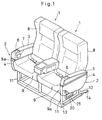
- the seat for a disabled person according to this embodiment is mounted to be disposed in a passenger cabin of an airplane.
- a plurality of seats 1 and 1 are articulated to constitute a set of seats for two passengers or three passengers.
- An armrest 2 is provided on one side end portion, that is, on the walkway side of the seat 1.
- the armrest 2 comprises the so-called armrest with a wing which contains a table 5 in a wing 4 by opening upward an arm cap 3 formed on the upper surface of the armrest 2.
- an ashtray 6 is provided on the armrest 2 in front of the arm cap 3.
- a PCU (Printed Circuit Unit) 7 which includes operating buttons for adjusting the sound-volume of an earphone or switching channels, is provided on the inner surface of the seat side of the wing 4.
- a base frame tube 10 adapted to form a seat frame for supporting a seat-back 8, a seat-bottom 9 and the like is supported by a front leg 11 and a rear leg 12.
- the lower ends of the front leg 11 and the rear leg 12 are fixed on a rail R disposed on the floor side by means of mounting fixtures 13 and 14, respectively.
- a shock absorber 15 is interposed between the front leg 11 and the rear leg 12 for absorbing the shock load applied to the seat in the case of emergency.
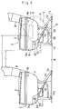
- the above armrest 2 is usually supported on the end portion of the base frame tube 10 by means of a stay 17 which is fixed on the lower surface of an armrest frame 16 forming the above armrest so as to extend downward therefrom.
- the armrest 2 is fixed to be turned vertically with respect to the seat frame by a horizontal rotational shaft 18 provided at a slightly higher position on the rear portion of the armrest 2.
- the outer surface of the armrest 2 is covered by an armrest cover 19.
- a locking device 20 enabling the locking and the releasing of the locking.
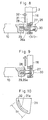
- a sleeve 21 which is positioned coaxially with the base frame tube 10 in the normal state, is provided at the lower end of the stay 17 for connecting and supporting the armrest 2 with respect to the base frame tube 10.
- a column-like sliding shaft 22 being slidable both in the sleeve 21 and in the base frame tube 10 is disposed, and which can be removably inserted in the base frame tube 10.
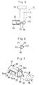
- a pair of guide pins 23 are formed around the outer peripheral surface of the sliding shaft 22 so as to oppositely project in the diameter direction, and substantially inverse U-shaped guide grooves 24 for inserting the guide pins 23 therethrough are formed around the cylindrical wall of the sleeve 21 in which the sliding shaft 22 is turnably fitted.
- Each of the guide pins 23 is movable along the formation direction of the guide groove 24 in such a state as to be inserted in the guide groove 24. Accordingly, by rotation of the sliding 22 around its axis, the guide pins 23 projectingly provided around the outer peripheral surface of the sliding shaft 22 at both the ends in the diameter direction are each operated to be engaged with or disengaged from the U-shaped terminals 24a or 24c of the guide grooves 24.
- a knob 25 is provided on the axial outer end portion of the sliding shaft 22, so that a passenger or a crewman holds the knob 25, and can turn the sliding shaft 22 along the guide groove grooves 24 and simultaneously push or pull it in the axial direction.
- the sliding shaft 22 and the guide pins 23 projectingly provided around the sliding shaft 22 are moved in the longitudinal direction, that is, in the axial direction along central portions 24b of the U-shaped guide grooves 24, so that the sliding shaft 22 can be removed from or fitted in the base frame tube 10.
- the central portion 24b of the guide groove 24 is formed in such a length that the sliding shaft 22 can be sufficiently fitted in or removed from the base frame tube 10 (see Fig. 7).
- the disabled person moves the guide pins 23 while turning it counterclockwise to engaged the guide pins 23 with the other terminals 24c of the guide grooves 24 (in the direction of the arrow C).
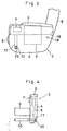
- he can turn the armrest 2 counterclockwise by its deadweight, or pressing-down by the hand, and can sink downward the front side of the armrest 2 (the position shown as the arrow D).
- a side portion 9a of the seat-bottom 9 is sufficiently exposed, so that the disabled person can ensure the space enough to move from the wheelchair and to sit on the seat. Namely, as shown in Fig.
- the seat releasing dimension between the back surface of a seat-back 8 of the front seat and the armrest 2 of the rear seat is L2; however, according to the present invention, after the front end portion of the armrest 2 is moved downward, the seat releasing dimension between the back surface of the seat-back 8 and the armrest 2 becomes L1 (L2 ⁇ L1).
- the dimension L1 which is enough for the disabled person to move his waist from the wheelchair to the side portion of the seat-bottom 9, can be formed on the side portion of the seat. This makes it possible to sufficiently ensure the space L1 required for the movement of the disabled person as compared with the conventional seat.
- the disabled person After completing the movement to sit down on the seat, the disabled person lifts up the armrest 2 and returns it to the usable position, and presses the knob 25 in the reversed direction so as to insert the sliding shaft 22 in the base frame tube 10. After that, by turning of the knob 25 in the direction reversed to the direction described-above, the guide pins 23 are engaged with the one-sided U-shaped terminals 24a of the guide grooves 24 again, thus performing locking action.
- the locking action of the locking device 20 is easily released to release the locking of the armrest 2 to the seat frame, so that the armrest 2 is freely turned to around the rotational shaft 18.
- a spring for biasing the sliding shaft 22 toward the inner side of the base frame tube 10 may be provided.
- a guide plate (not shown) continuous front the end portion of the base frame tube 10 may be provided to guide the end portion of the insertion side of the sliding shaft 22 for allowing the sliding shaft 22 to be easily re-inserted when the armrest 2 is returned.
- a spring (not shown) for biasing the guide pins 23 in the circumferential direction may be provided on the sliding shaft 22.
- a stopper (not shown) may be provided for preventing the front side of the armrest 2 from being not excessively turned upward. In this case, the stopper is effective to position the armrest 2 when the armrest 2 is returned, and to make easy the return of the armrest 2.
- a spring (not shown) for canceling the weight of the armrest 2 may be provided.
- Figs. 8 to 10 show a modification of a locking mechanism 20, where in a locking screw 26 is used in place of the above-described sliding shaft 22.
- the locking screw 26 is mounted in such a manner as to be axially slidable with respect to a locking guide 27 formed on the lower end of the armrest 2 in the range of a specified stroke S1.
- a male screw 26a is threaded at the leading edge of the locking screw 26 and a stopper 28 is formed on the inner end of the male screw 26a for preventing the fallout of the locking screw 26 to the surface side of the locking guide 27.
- the stopper 28 prevents the further screwing of the male screw 26a of the locking screw 26 in such a state that the screw 26a is perfectly screwed with a female screw 29 formed on the base frame tube 10, and the reby functions to prevent the breakage of the locking guide 27 due to the excessive-fastening of the male screw 26a.
- a knob 30 is integrally formed on a head portion of the locking screw 26, that is, on the surface side of the locking guide 27. By suitable turning of the knob 30, the locking screw 26 can be fastened to and loosened from the female screw 29 on the base frame tube 10 side.
- reference numeral 31 indicates an angle restricting plate substantially fan-shaped, which is fixed on a base frame (not shown) side of the seat.
- a circular-arc guide groove 31a is formed along the inner side of an outer peripheral circular-arc portion, and a pin 32 projecting from the armrest frame 16 side is inserted in the guide groove 31a.
- the front side of the armrest 2 can be shifted in the vertical direction.
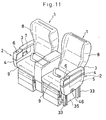
- Figs. 11 to 16 show a second embodiment of a seat for a disabled person. Parts corresponding to those in the first embodiment are indicated at the same symbols, and the explanation thereof is omitted.
- an armrest 2 is usually supported on the side end portion of base frame tubes 10 by a pair of stays 17 and 17 which are longitudinally fixed on the lower surface of an arm rest frame 16 forming the skeleton of the arm rest 2 in such a manner as to extend downward.
- the arm rest 2 is supported through rails 33 and 33 vertically fixed on the side end portions of the base frame tubes 10, and brackets 34 are fixedly provided between the rails 33 and 33 and the base frame tubes 10 to prevent the tilting of the rails 33 and 33.
- a rail supporting plate 35 is interposed between both the rails 33 and 33 for accurately keeping the distance between the two rails 33 and 33 disposed oppositely to each other.
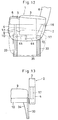
- Each of the rails 33 and 33 is substantially U-shaped in the cross-section (see Fig. 14), and a slider 36 is inserted in the rail 33 so as to be slidably moved in the vertical direction.
- the sliders 36 are fixed on the arm rest 2 side. Namely, the sliders 36 are each fixed at the stays 17 and 17 on the armrest 2 side by two supporting shafts 37 and 37 provided so as to correspond to opening portions formed on the side surfaces of the rails 33.
- a locking device 20 is formed at the uppermost ends of the rails 33 for locking the sliders 36 in such a state that the sliders 36 are positioned at the uppermost ends of the rails 33.
- the locking device 20 has such a mechanism as to insert lock pins 38 in the sliders 36 and the rails 33. Namely, each lock pin 38 passes through a though-hole 39 perforated on the rail 33, and further, the leading edge of the lock pin 38 is fitted in a recessed portion 40 formed on the slider 36 (see Fig. 16). Further, the locking pin 38 is supported by a pin guide 41 so as to be movable in the horizontal direction, and is fixed on a connecting lever 42 provided inside the armrest 2 by a supporting member 43, The connecting lever 42 is intended to connect the two stays 17 and 17 to each other.
- a link 44 is turnably pin-connected at the other end of the locking pin 38.
- the other end of the link 44 is turnably pin-connected on the upper end or the lower end of a crank 45.
- the crank 45 is mounted at a substantially central portion of the connecting lever 42 in such a manner as to be turnable around the center portion of the crank 44 (in the direction of the arrow E).
- the crank 45 can be freely turned by a knob 46 formed on the crank 45. Namely, the knob 46 is fixed on the crank 45, and passes through a side panel 47 of the armrest 2 to be exposed to the outside. The exposed portion of the knob 46 lies in a recessed portion 48 formed on the side panel 47, to be thus easily held by the hand.
- the sliders 36 are slid downward within the rails 33 to descend the armrest 2. Further, the locking pins 38 are inserted in the pin guides 41, and the pin guides 41 are slid along the side surfaces of the rails 33 to be moved downward. As the armrest 2 is sufficiently sunk, the side surface 9a of the seat-bottom 9 can be sufficiently exposed from the upper portion of the armrest 2. Thus, the disabled person can move from the wheelchair to the seat and sit on the seat. The armrest 2 does not obstruct the above movement of the disabled person.
- the disabled person takes up the armrest 2 again, to return it to the normal service position, and rotates the knob 46 in the reversed direction. With this action, the leading edges of the locking pins 38 are fitted in the recessed portions 40 of the sliders 36 again to be thus engaged therewith.
- the sliders 36 provided on the stays 17 of the armrest 2 are supported in the vicinity of the ends portions of the base frame tubes 10 of the seat through the rails 33.
- the side surface of the seat-bottom can be sufficiently exposed by moving downward the front end or the whole of the armrest, which enables the disabled person to easily sit on or separate from the seat from the side of the seat. Therefore, the extremely large effect can be obtained by carrying out the present invention.
- a seat for a disabled person is characterized in that said armrest is movable in a downward direction between a first or regular position where the access to said seat bottom is possible only from the front of said seat and a second or access position where at least a side portion of said seat bottom is exposed and that said armrest is locked in said first or regular position by means of a locking device situated in said wing and connecting said wing with a supporting device, said supporting device forming part of or being connected to said seat frame.
- the seat pitch is narrow and the armrest is of a type having a wing containing a table just as in a business class seat of an airplane
- a disabled person can easily sit on or separate from the seat by shifting the armrest to largely expose the surface of the seat bottom.
- the seat for a disabled person can be carried out as a seat with an armrest for various vehicles such as an airplane, ship and rolling stock, and as well as contribute to the social rehabilitation of disabled persons.
Landscapes
- Engineering & Computer Science (AREA)
- Aviation & Aerospace Engineering (AREA)
- Mechanical Engineering (AREA)
- Transportation (AREA)
- Seats For Vehicles (AREA)
Abstract
Claims (21)
- Siège pour véhicule comprenant un cadre de siège, un dossier de siège (8), une assise de siège (9), et au moins un accoudoir (2) comprenant un cadre d'accoudoir (16), une aile (4) disposée dans un plan vertical et fixée audit cadre au moyen d'un élément support (17) fixé audit cadre d'accoudoir (16), et une tablette (5) logée à l'intérieur de ladite aile (4), caractérisé en ce que ledit accoudoir (2) peut se déplacer vers le bas entre une première position, ou position normale, dans laquelle l'accès à ladite assise de siège (9) n'est possible que par l'avant dudit siège, et une seconde position, ou position d'accès, dans laquelle une partie latérale (9a) au moins de ladite assise de siège (9) est dégagée, et en ce que ledit accoudoir (2) est verrouillé dans ladite première position, ou position normale, au moyen d'un dispositif de verrouillage (20) situé dans ladite aile (4) et reliant ladite aile (4) à un dispositif support (10, 33), ledit dispositif support (10, 33) faisant partie dudit cadre de siège ou étant fixé sur celui-ci.
- Siège selon la revendication 1, caractérisé en ce que ledit accoudoir (2) est fixé sur un axe de rotation horizontal (18) prévue sur la partie arrière dudit accoudoir (2), et en ce que ledit dispositif de verrouillage (20) comprend un élément de fixation (22, 26) pouvant être inséré de façon amovible dans un tube de cadre inférieur (10) adapté pour former ledit cadre de siège.
- Siège selon la revendication 2, caractérisé en ce que ledit élément de fixation est une tige coulissante (22) en forme de cylindre qui est disposée à l'intérieur d'un manchon (21) prévu à l'extrémité inférieure dudit élément support (17) et positionné de façon coaxiale par rapport au tube de cadre inférieur (10) adapté pour former ledit cadre de siège.
- Siège selon la revendication 3, caractérisé en ce qu'un élément de ressort est prévu pour exercer sur ladite tige coulissante (22) une force de rappel en direction de la face interne dudit tube de cadre inférieur (10).
- Siège selon la revendication 4, caractérisé en ce qu'il est prévu une plaque de guidage continue partant de la partie terminale dudit tube de cadre inférieur (10).
- Siège selon l'une au moins des revendications 3 à 5, caractérisé en ce que ladite tige coulissante comporte un moyen de verrouillage (23) qui s'engage dans un moyen de verrouillage complémentaire (24) prévu sur ladite tige coulissante (22).
- Siège selon la revendication 6, caractérisé en ce que ledit moyen de verrouillage est constitué par deux tiges de guidage (23) prévues autour de la surface périphérique externe de ladite tige coulissante (22), de façon a dépasser de façon diamétralement opposée, et en ce que ledit moyen de verrouillage complémentaire est constitué par des rainures de guidage (24) ayant essentiellement la forme d'un U renversé, formées dans la paroi cylindrique dudit manchon (21).
- Siège selon la revendication 7, caractérisé en ce qu'un élément de ressort est prévu pour exercer sur lesdites tiges de guidage (23), une force de rappel dans le sens de la circonférence.
- Siège selon la revendication 2, caractérisé en ce que ledit élément de fixation est une vis de blocage (26) dont la partie filetée (26a) peut se visser dans un alésage taraudé (29) prévu dans ledit tube de cadre inférieur (10).
- Siège selon la revendication 9, caractérisé en ce qu'un guide de verrouillage (27) est prévu pour empêcher que ladite vis de blocage (26) ne sorte de la surface latérale dudit guide de verrouillage (27) ou bien que ladite partie filetée (26a) ne se bloque par un serrage excessif.
- Siège selon l'une au moins des revendications 2 à 10, caractérisé en ce qu'une plaque de limitation de débattement angulaire (31) est fixée audit cadre inférieur, ladite plaque de limitation de débattement angulaire (31) comportant une rainure de guidage (31a) en arc de cercle, et en ce qu'un ergot (32) dépassant dudit cadre d'accoudoir (16) est introduit dans ladite rainure de guidage (31a).
- Siège selon l'une au moins des revendications 2 à 11, caractérisé en ce qu'un élément de ressort est prévu pour compenser le poids dudit accoudoir (2).
- Siège selon la revendication 1, caractérisé en ce que des coulisseaux (36) sont fixés audit accoudoir (2) et peuvent glisser à l'intérieur de rails (33) fixés verticalement audit cadre de siège, et en ce que ledit dispositif de verrouillage (20) est doté d'éléments de verrouillage (38) qui peuvent être engagés de façon amovible en traversant lesdits coulisseaux (36) et lesdits rails (33).
- Siège selon la revendication 13, caractérisé en ce qu'une biellette (44) est montée en rotation entre lesdits éléments de verrouillage (38) et un élément de manivelle (45).
- Siège selon l'une ou l'autre des revendications 13 et 14, caractérisé en ce que lesdits éléments de verrouillage (38) sont guidés par des moyens de guidage (41) fixés sur des éléments supports (43).
- Siège selon la revendication 15, caractérisé en ce que lesdits moyens supports (43) sont fixés sur un élément de liaison (42) reliant lesdits éléments supports (17).
- Siège selon la revendication 16, caractérisé en ce que ledit élément de manivelle (45) est fixé sur ledit élément de liaison (42).
- Siège selon l'une au moins des revendications 13 à 17, caractérisé en ce que lesdits éléments de verrouillage sont des tiges de verrouillage (38) passant à l'intérieur de trous traversants (39) percés dans lesdits rails (33), l'extrémité frontale desdites tiges de verrouillage (38) venant se loger dans des logements (40) prévus à l'intérieur desdits coulisseaux (36).
- Siège selon l'une au moins des revendications 13 à 18, caractérisé en ce que des étriers (34) sont fixés entre lesdits rails (33) et les tubes de cadre inférieur (10) pour empêcher le basculement des dits rails (33).
- Siège selon l'une au moins des revendications 13 à 19, caractérisé en ce qu'une platine support de rail (35) est disposée entre deux rails (33) pour maintenir l'écartement desdits rails (33).
- Siège selon l'une quelconque des revendications précédentes, caractérisé en ce que ledit dispositif de verrouillage (20) comporte des éléments de commande de déplacement (25, 30, 46) qui dépassent de la surface externe de ladite aile (4).
Applications Claiming Priority (5)
| Application Number | Priority Date | Filing Date | Title |
|---|---|---|---|
| JP331071/92 | 1992-11-16 | ||
| JP4331071A JP2689059B2 (ja) | 1992-11-16 | 1992-11-16 | 身体障害者用座席 |
| JP4339742A JP2745180B2 (ja) | 1992-11-26 | 1992-11-26 | 身体障害者用座席 |
| JP339742/92 | 1992-11-26 | ||
| PCT/JP1993/001679 WO1994011247A1 (fr) | 1992-11-16 | 1993-11-16 | Siege pour handicapes physiques |
Publications (3)
| Publication Number | Publication Date |
|---|---|
| EP0621174A1 EP0621174A1 (fr) | 1994-10-26 |
| EP0621174A4 EP0621174A4 (fr) | 1995-01-04 |
| EP0621174B1 true EP0621174B1 (fr) | 1998-02-04 |
Family
ID=27307195
Family Applications (1)
| Application Number | Title | Priority Date | Filing Date |
|---|---|---|---|
| EP93924832A Expired - Lifetime EP0621174B1 (fr) | 1992-11-16 | 1993-11-16 | Siege pour handicapes physiques |
Country Status (1)
| Country | Link |
|---|---|
| EP (1) | EP0621174B1 (fr) |
Families Citing this family (4)
| Publication number | Priority date | Publication date | Assignee | Title |
|---|---|---|---|---|
| ITRM20010029U1 (it) * | 2001-02-26 | 2002-08-26 | Aviointeriors S P A | Poltrona perfezionata, in particolare per aeromobili. |
| DE502006005357D1 (de) | 2006-09-21 | 2009-12-24 | Lufthansa Technik Ag | Falttischanordnung |
| EP2443033B1 (fr) | 2009-06-19 | 2016-12-07 | Recaro Aircraft Seating GmbH & Co. KG | Système de siège passager |
| PT110364B (pt) * | 2017-10-23 | 2021-03-01 | Instituto Superior Técnico | Assento híbrido para pessoas com mobilidade reduzida no transporte aéreo. |
Family Cites Families (1)
| Publication number | Priority date | Publication date | Assignee | Title |
|---|---|---|---|---|
| DE3512953C2 (de) * | 1985-04-11 | 1987-04-02 | Daimler-Benz Ag, 7000 Stuttgart | Sitz zum Mittelgang eines Omnibusses |
-
1993
- 1993-11-16 EP EP93924832A patent/EP0621174B1/fr not_active Expired - Lifetime
Also Published As
| Publication number | Publication date |
|---|---|
| EP0621174A4 (fr) | 1995-01-04 |
| EP0621174A1 (fr) | 1994-10-26 |
Similar Documents
| Publication | Publication Date | Title |
|---|---|---|
| US5131607A (en) | Extendable and retractable aircraft seat assembly | |
| US5727845A (en) | Armrest arrangements in convertible aircraft passenger seating | |
| US5178345A (en) | Extendible and retractable aircraft seat assembly | |
| US4917438A (en) | Adjustable-width seating for passenger-carrying vehicles | |
| US20140319275A1 (en) | Compact cabin attendant seat stowage | |
| JP4440890B2 (ja) | 乗り物の内部空間を変更する方法と、その方法を実現するための座席 | |
| US5584534A (en) | Seat for disabled person | |
| EP3248875B1 (fr) | Siège d'agent de bord, système comprenant un siège d'agent de bord ainsi qu'un dispositif et un système comprenant une zone d'aéronef | |
| US6749266B2 (en) | Locking collar for passenger seat back recline assembly | |
| JPH07223594A (ja) | 乗物、特に航空機用の複数の隣接する座席を具備する構造 | |
| EP0621174A1 (fr) | Siege pour handicapes physiques | |
| EP4003839B1 (fr) | Unité de salon pour passager d'aéronef pourvue d'un repose-pieds mobile | |
| DE102017204894A1 (de) | Passagiersitz mit einem erweiterbaren Sitzelement und Passagierkabinenbereich | |
| EP4321435B1 (fr) | Système de support de couchage déployable pour passagers assis | |
| KR20060010948A (ko) | 자동차용 시트의 워크인 장치 | |
| JP2745180B2 (ja) | 身体障害者用座席 | |
| JP2000103271A (ja) | 倒立シート | |
| KR100502144B1 (ko) | 버스용 시트 | |
| US12371166B2 (en) | Deployable sleep support system for seated passengers | |
| KR0121367Y1 (ko) | 승용차의 보조시트 장치 | |
| KR200324044Y1 (ko) | 차량용 시이트이송트랙의 록킹장치 | |
| JP2689059B2 (ja) | 身体障害者用座席 | |
| JPS6236660Y2 (fr) | ||
| KR20000012181U (ko) | 차량의 조수석 풋 레스트 | |
| KR20060072158A (ko) | 차량용 시트의 워크인 장치 |
Legal Events
| Date | Code | Title | Description |
|---|---|---|---|
| PUAI | Public reference made under article 153(3) epc to a published international application that has entered the european phase |
Free format text: ORIGINAL CODE: 0009012 |
|
| 17P | Request for examination filed |
Effective date: 19940616 |
|
| AK | Designated contracting states |
Kind code of ref document: A1 Designated state(s): DE FR GB IT |
|
| A4 | Supplementary search report drawn up and despatched | ||
| AK | Designated contracting states |
Kind code of ref document: A4 Designated state(s): DE FR GB IT |
|
| 17Q | First examination report despatched |
Effective date: 19951020 |
|
| GRAG | Despatch of communication of intention to grant |
Free format text: ORIGINAL CODE: EPIDOS AGRA |
|
| GRAG | Despatch of communication of intention to grant |
Free format text: ORIGINAL CODE: EPIDOS AGRA |
|
| GRAH | Despatch of communication of intention to grant a patent |
Free format text: ORIGINAL CODE: EPIDOS IGRA |
|
| GRAH | Despatch of communication of intention to grant a patent |
Free format text: ORIGINAL CODE: EPIDOS IGRA |
|
| GRAA | (expected) grant |
Free format text: ORIGINAL CODE: 0009210 |
|
| AK | Designated contracting states |
Kind code of ref document: B1 Designated state(s): DE FR GB IT |
|
| REF | Corresponds to: |
Ref document number: 69316874 Country of ref document: DE Date of ref document: 19980312 |
|
| ET | Fr: translation filed | ||
| ITF | It: translation for a ep patent filed | ||
| PLBE | No opposition filed within time limit |
Free format text: ORIGINAL CODE: 0009261 |
|
| STAA | Information on the status of an ep patent application or granted ep patent |
Free format text: STATUS: NO OPPOSITION FILED WITHIN TIME LIMIT |
|
| 26N | No opposition filed | ||
| REG | Reference to a national code |
Ref country code: GB Ref legal event code: IF02 |
|
| PGFP | Annual fee paid to national office [announced via postgrant information from national office to epo] |
Ref country code: GB Payment date: 20100929 Year of fee payment: 18 |
|
| PGFP | Annual fee paid to national office [announced via postgrant information from national office to epo] |
Ref country code: FR Payment date: 20101123 Year of fee payment: 18 |
|
| PGFP | Annual fee paid to national office [announced via postgrant information from national office to epo] |
Ref country code: DE Payment date: 20101129 Year of fee payment: 18 |
|
| PGFP | Annual fee paid to national office [announced via postgrant information from national office to epo] |
Ref country code: IT Payment date: 20101124 Year of fee payment: 18 |
|
| GBPC | Gb: european patent ceased through non-payment of renewal fee |
Effective date: 20111116 |
|
| REG | Reference to a national code |
Ref country code: FR Ref legal event code: ST Effective date: 20120731 |
|
| PG25 | Lapsed in a contracting state [announced via postgrant information from national office to epo] |
Ref country code: IT Free format text: LAPSE BECAUSE OF NON-PAYMENT OF DUE FEES Effective date: 20111116 |
|
| REG | Reference to a national code |
Ref country code: DE Ref legal event code: R119 Ref document number: 69316874 Country of ref document: DE Effective date: 20120601 |
|
| PG25 | Lapsed in a contracting state [announced via postgrant information from national office to epo] |
Ref country code: GB Free format text: LAPSE BECAUSE OF NON-PAYMENT OF DUE FEES Effective date: 20111116 |
|
| PG25 | Lapsed in a contracting state [announced via postgrant information from national office to epo] |
Ref country code: FR Free format text: LAPSE BECAUSE OF NON-PAYMENT OF DUE FEES Effective date: 20111130 |
|
| PG25 | Lapsed in a contracting state [announced via postgrant information from national office to epo] |
Ref country code: DE Free format text: LAPSE BECAUSE OF NON-PAYMENT OF DUE FEES Effective date: 20120601 |