EP0621191A1 - Méthode de fabrication d'une boîte rectangulaire rabattable et boîte fabriquee par cette méthode - Google Patents
Méthode de fabrication d'une boîte rectangulaire rabattable et boîte fabriquee par cette méthode Download PDFInfo
- Publication number
- EP0621191A1 EP0621191A1 EP94201000A EP94201000A EP0621191A1 EP 0621191 A1 EP0621191 A1 EP 0621191A1 EP 94201000 A EP94201000 A EP 94201000A EP 94201000 A EP94201000 A EP 94201000A EP 0621191 A1 EP0621191 A1 EP 0621191A1
- Authority
- EP
- European Patent Office
- Prior art keywords
- box
- bottom parts
- folded
- injection molding
- fabricated
- Prior art date
- Legal status (The legal status is an assumption and is not a legal conclusion. Google has not performed a legal analysis and makes no representation as to the accuracy of the status listed.)
- Withdrawn
Links
- 238000000034 method Methods 0.000 title claims abstract description 22
- 238000001746 injection moulding Methods 0.000 claims abstract description 17
- 239000000463 material Substances 0.000 claims abstract description 11
- 238000002347 injection Methods 0.000 claims abstract description 7
- 239000007924 injection Substances 0.000 claims abstract description 7
- 229920003023 plastic Polymers 0.000 claims abstract description 5
- 239000004033 plastic Substances 0.000 claims abstract description 5
- 239000002131 composite material Substances 0.000 claims description 3
- 230000002349 favourable effect Effects 0.000 abstract 1
- 238000004519 manufacturing process Methods 0.000 description 5
- 238000007493 shaping process Methods 0.000 description 1
Images
Classifications
-
- B—PERFORMING OPERATIONS; TRANSPORTING
- B65—CONVEYING; PACKING; STORING; HANDLING THIN OR FILAMENTARY MATERIAL
- B65D—CONTAINERS FOR STORAGE OR TRANSPORT OF ARTICLES OR MATERIALS, e.g. BAGS, BARRELS, BOTTLES, BOXES, CANS, CARTONS, CRATES, DRUMS, JARS, TANKS, HOPPERS, FORWARDING CONTAINERS; ACCESSORIES, CLOSURES, OR FITTINGS THEREFOR; PACKAGING ELEMENTS; PACKAGES
- B65D1/00—Rigid or semi-rigid containers having bodies formed in one piece, e.g. by casting metallic material, by moulding plastics, by blowing vitreous material, by throwing ceramic material, by moulding pulped fibrous material or by deep-drawing operations performed on sheet material
- B65D1/22—Boxes or like containers with side walls of substantial depth for enclosing contents
- B65D1/225—Collapsible boxes
-
- B—PERFORMING OPERATIONS; TRANSPORTING
- B29—WORKING OF PLASTICS; WORKING OF SUBSTANCES IN A PLASTIC STATE IN GENERAL
- B29C—SHAPING OR JOINING OF PLASTICS; SHAPING OF MATERIAL IN A PLASTIC STATE, NOT OTHERWISE PROVIDED FOR; AFTER-TREATMENT OF THE SHAPED PRODUCTS, e.g. REPAIRING
- B29C45/00—Injection moulding, i.e. forcing the required volume of moulding material through a nozzle into a closed mould; Apparatus therefor
- B29C45/0081—Injection moulding, i.e. forcing the required volume of moulding material through a nozzle into a closed mould; Apparatus therefor of objects with parts connected by a thin section, e.g. hinge, tear line
Definitions
- the invention relates to a method for fabricating a collapsible rectangular box with four walls interconnected by folding lines and a bottom comprising four bottom parts each connected with a wall through a folding line, said bottom parts being grouped in two pairs at least partially overlapping each other in the folded-out position of the box and each pair comprising adjoining bottom parts interconnected by a folding line. Further the invention relates to a box fabricated using said method.
- a flat sheet of appropriate material mostly cardboard
- This plane sheet generally comprises the four aligned walls and the bottom parts each connected with one of the walls.
- the first and fourth wall are foldably interconnected (for example by bonding a strip integral with one of these walls onto the other wall), whereas in a corresponding manner also the bottom parts are interconnected two by two into two pairs.
- the box is obtained in its collapsed position.
- the box may be extended to its folded-out position of use.
- the method according to the invention is characterised in that the box is fabricated from plastics material by injection molding, wherein all folding lines comprise living hinges made of thin sections of material.
- the process of injection molding enables the fabrication of the walls, the bottom parts and required folding lines therebetween in one fabrication step without the need of forming connections afterwards.
- the injection mold it is possible to directly shape the folding lines as living hinges, such that after being removed from the mold the box basically is directly ready for use.
- the box is injection molded in a position between its completely folded-out position and its completely collapsed position. Injection molding the box in such a position leads to a simple injection molding process, in which the complexity of the injection mold is minimized and wherein the box basically is self-releasing from the injection mold.
- connection elements are provided at those locations of the bottom parts, where these overlap each other when the box is folded-out. Using these connection elements the box may be locked in the folded-out position, wherein especially connections are created between the bottom parts.
- connection elements are anchored in the respective bottom parts during injection molding, such that shaping these connection elements does not bring about additional fabrication steps, but on the other hand it is possible too that the connection elements are connected with the respective bottom parts after injection molding.
- connection elements comprise the composite parts of a "Velcro"-type connector, a push-button type connector, or alike.
- Such a connection may be released at choice, such that the box can be collapsed or folded out, respectively, many times.
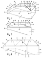
- a box is shown fabricated using the method according to the invention, illustrated in a position between its fully folded-out and its fully collapsed position.
- the embodiment of the box shown is meant for displaying objects.
- the box comprises two oppositely positioned walls 1 and 2 each having an inclined upper edge and two walls 3 and 4 interconnecting the walls 1 and 2.
- the walls are interconnected by living hinges 5-8 acting as folding lines.
- Bottom parts 9-12 connect to the bottom edge of each of the walls 1-4.
- the connections between these bottom parts 9-12 and the corresponding walls 1-4 also exist of folding lines 13-16 comprising living hinges.
- pairs of adjoining bottom parts 9 and 12 or 10 and 11, respectively are interconnected by folding lines 17 and 18, respectively, comprising living hinges.
- the folding lines 17 and 18 intersect the folding lines 13 and 16 or 14 and 15, respectively, at an angle of 45° Or in other words, the folding lines 17 and 18 are positioned in bisector planes between the walls 1 and 4 and the walls 2 and 3, respectively.
- fig. 1 shows at the inward side of the bottom part 10 and on the outward side of the bottom part 9 composite parts 19 and 20 of a push-button type connector or alike.
- the box illustrated in fig. 1 is open at its top (in fig. 1 represented at the lower side), such that it can receive products.
- the box In the position shown in fig. 1 the box can be fabricated using the method according to the invention.
- an appropriate injection molding mold is applied, in which the box may be manufactured from plastics material by injection molding.
- the folding lines 5-8 and 13-18 are shaped as living hinges made of thin sections of material.
- the box As a result of the position of the box shown in fig. 1 it is self-releasing from the injection mold (not shown), such that the box can be fabricated in one single fabrication step.
- the push button parts 19 and 20 acting as connection elements between the pairs of bottom parts 9, 12 and 10, 11 may be anchored into the respective bottom parts during injection molding, or may be connected with the respective bottom parts after injection molding. It is noted that corresponding connection elements are provided at the bottom parts 11 and 12 which however are not visible in the drawing.
- fig. 3 illustrates the fully collapsed position of the box, in which it is completely flat.
- the walls 1 and 3 are aligned, as are the walls 2 and 4.
- the walls 1 and 3 lie in pairs along the walls 2 and 4.
- the folding lines 17 and 18, which define the connections between the bottom parts 9, 12 and 10, 11, respectively enclose an angle of 45° with the folding lines 13 and 14, respectively.
- the invention is not limited to the embodiments described before, which can be varied widely within the scope of the invention as defined by the claims.
- the position, in which the box is fabricated during injection molding may divert from the position shown in fig. 1.
- a push-button like connection 19 20 every other type of connection may be applied, such as a "Velcro"-type connection.
- the overlapping parts of the bottom pairs are definitively bonded together after folding out the box. In such a case the box generally is not fit for repeated use.
Landscapes
- Engineering & Computer Science (AREA)
- Mechanical Engineering (AREA)
- Ceramic Engineering (AREA)
- Manufacturing & Machinery (AREA)
- Rigid Containers With Two Or More Constituent Elements (AREA)
- Injection Moulding Of Plastics Or The Like (AREA)
- Cartons (AREA)
Applications Claiming Priority (2)
| Application Number | Priority Date | Filing Date | Title |
|---|---|---|---|
| NL9300673 | 1993-04-21 | ||
| NL9300673A NL9300673A (nl) | 1993-04-21 | 1993-04-21 | Werkwijze voor het vervaardigen van een samenvouwbare rechthoekige doos alsmede doos vervaardigd met behulp van deze werkwijze. |
Publications (1)
| Publication Number | Publication Date |
|---|---|
| EP0621191A1 true EP0621191A1 (fr) | 1994-10-26 |
Family
ID=19862307
Family Applications (1)
| Application Number | Title | Priority Date | Filing Date |
|---|---|---|---|
| EP94201000A Withdrawn EP0621191A1 (fr) | 1993-04-21 | 1994-04-13 | Méthode de fabrication d'une boîte rectangulaire rabattable et boîte fabriquee par cette méthode |
Country Status (2)
| Country | Link |
|---|---|
| EP (1) | EP0621191A1 (fr) |
| NL (1) | NL9300673A (fr) |
Cited By (2)
| Publication number | Priority date | Publication date | Assignee | Title |
|---|---|---|---|---|
| GB2310188A (en) * | 1996-02-13 | 1997-08-20 | John Harris | Collapsible container |
| EP4678546A1 (fr) * | 2025-02-05 | 2026-01-14 | Plast 1 A/S | Boîte pliante, ensemble de boîtes pliantes et procédé de fabrication d'une boîte pliante |
Citations (2)
| Publication number | Priority date | Publication date | Assignee | Title |
|---|---|---|---|---|
| GB2117356A (en) * | 1982-03-25 | 1983-10-12 | Tungum Hydraulics Ltd | Cartons |
| JPS60178033A (ja) * | 1984-02-27 | 1985-09-12 | Fuji Photo Film Co Ltd | 熱可塑性樹脂製容器の製造方法 |
-
1993
- 1993-04-21 NL NL9300673A patent/NL9300673A/nl not_active Application Discontinuation
-
1994
- 1994-04-13 EP EP94201000A patent/EP0621191A1/fr not_active Withdrawn
Patent Citations (2)
| Publication number | Priority date | Publication date | Assignee | Title |
|---|---|---|---|---|
| GB2117356A (en) * | 1982-03-25 | 1983-10-12 | Tungum Hydraulics Ltd | Cartons |
| JPS60178033A (ja) * | 1984-02-27 | 1985-09-12 | Fuji Photo Film Co Ltd | 熱可塑性樹脂製容器の製造方法 |
Non-Patent Citations (1)
| Title |
|---|
| PATENT ABSTRACTS OF JAPAN vol. 10, no. 18 (M - 448)<2075> 24 January 1986 (1986-01-24) * |
Cited By (2)
| Publication number | Priority date | Publication date | Assignee | Title |
|---|---|---|---|---|
| GB2310188A (en) * | 1996-02-13 | 1997-08-20 | John Harris | Collapsible container |
| EP4678546A1 (fr) * | 2025-02-05 | 2026-01-14 | Plast 1 A/S | Boîte pliante, ensemble de boîtes pliantes et procédé de fabrication d'une boîte pliante |
Also Published As
| Publication number | Publication date |
|---|---|
| NL9300673A (nl) | 1994-11-16 |
Similar Documents
| Publication | Publication Date | Title |
|---|---|---|
| US5395043A (en) | A blank for making a box around a load | |
| US5899336A (en) | Sheet of corrugated paper for producing a package | |
| US6223978B1 (en) | Octagonal package | |
| US6520898B1 (en) | Process of making a compartmented container | |
| US5044547A (en) | Decorative tray or tray cover | |
| US4576329A (en) | Collapsible container | |
| US5390790A (en) | Octagonal container with smooth inner bottom surface | |
| US4688673A (en) | Foldup paper container | |
| US4658961A (en) | Foldable case blank | |
| EP0621191A1 (fr) | Méthode de fabrication d'une boîte rectangulaire rabattable et boîte fabriquee par cette méthode | |
| EP0576325B1 (fr) | Plateau gerbable en carton ou matière analogue, plus particulièrement destiné au transport de gros fromages circulaires et flan pour sa réalisation | |
| US5421509A (en) | Folding box | |
| US5369938A (en) | Process for making one-piece boxes | |
| US4142666A (en) | Lock bottom carton | |
| US5009362A (en) | Quick-assembled folding carton with reinforced bottom that locks in position | |
| JPS604896Y2 (ja) | 仕切板 | |
| GB2205083A (en) | Boxes formed from blanks | |
| EP0799770B1 (fr) | Conteneurs en un matériau semi-rigide et flans prédécoupés et refoulés pour la réalisation de ces conteneurs | |
| EP0471915B1 (fr) | Procédé et appareil pour la fabrication d'une feuille préformé, apte à être pliée en un carton | |
| EP0784015B1 (fr) | Boíte contenant des flacons formée à partir d'une découpe unique en carton | |
| GB2217300A (en) | Box and blank | |
| JP2539614Y2 (ja) | 包装用箱 | |
| JP2743161B2 (ja) | 折り畳み式容器 | |
| RU2279498C2 (ru) | Изделие и способ его изготовления | |
| JPH082093Y2 (ja) | 容器の手提げ |
Legal Events
| Date | Code | Title | Description |
|---|---|---|---|
| PUAI | Public reference made under article 153(3) epc to a published international application that has entered the european phase |
Free format text: ORIGINAL CODE: 0009012 |
|
| AK | Designated contracting states |
Kind code of ref document: A1 Designated state(s): BE DE DK FR LU NL SE |
|
| 17P | Request for examination filed |
Effective date: 19950425 |
|
| 17Q | First examination report despatched |
Effective date: 19960513 |
|
| STAA | Information on the status of an ep patent application or granted ep patent |
Free format text: STATUS: THE APPLICATION IS DEEMED TO BE WITHDRAWN |
|
| 18D | Application deemed to be withdrawn |
Effective date: 19960924 |