EP0621458A1 - Instrument d'arpentage électronique - Google Patents
Instrument d'arpentage électronique Download PDFInfo
- Publication number
- EP0621458A1 EP0621458A1 EP94106074A EP94106074A EP0621458A1 EP 0621458 A1 EP0621458 A1 EP 0621458A1 EP 94106074 A EP94106074 A EP 94106074A EP 94106074 A EP94106074 A EP 94106074A EP 0621458 A1 EP0621458 A1 EP 0621458A1
- Authority
- EP
- European Patent Office
- Prior art keywords
- subsystem
- power source
- power
- memory
- program
- Prior art date
- Legal status (The legal status is an assumption and is not a legal conclusion. Google has not performed a legal analysis and makes no representation as to the accuracy of the status listed.)
- Granted
Links
Images









Classifications
-
- G—PHYSICS
- G06—COMPUTING OR CALCULATING; COUNTING
- G06F—ELECTRIC DIGITAL DATA PROCESSING
- G06F1/00—Details not covered by groups G06F3/00 - G06F13/00 and G06F21/00
- G06F1/26—Power supply means, e.g. regulation thereof
- G06F1/30—Means for acting in the event of power-supply failure or interruption, e.g. power-supply fluctuations
-
- G—PHYSICS
- G01—MEASURING; TESTING
- G01C—MEASURING DISTANCES, LEVELS OR BEARINGS; SURVEYING; NAVIGATION; GYROSCOPIC INSTRUMENTS; PHOTOGRAMMETRY OR VIDEOGRAMMETRY
- G01C1/00—Measuring angles
- G01C1/02—Theodolites
Definitions
- the present invention relates to an electronic survey instrument controlled based on computer programs.
- an object of the present invention is to provide an electronic survey instrument which can restore normally a display image, count values and so on immediately before a power-off time, when a power source is cut off and then resumed.
- a runaway may occur at the time of the next power-on operation because a program will seek for information which should be restored from a memory in vain or will find improper information.
- Another object of the present invention to provide an electronic survey instrument which can restore information saved in a memory at the following power-on time only in the case that the latest power-off operation was normally effected.
- the electronic survey instrument includes a main system which operates in accordance with a survey program, and plural subsystems each for operating based on a control signal from the main system, the plural subsystems including a survey subsystem for surveying, a display subsystem for displaying a result measured with the survey subsystem, and a power source subsystem for controlling a power source used for each of the main system, the survey subsystem, and the display subsystem.
- the main system includes resume means for saving information into a memory immediately before a power source is cut off and for restoring the information stored in the memory at the next power-on time; means for storing end information indicating that information saving process to the memory has been performed to cut normally off a power source; and canceling means for canceling an information restoring process by the resume means at the next power-on time in the case the end information has not been stored.
- the electronic survey instrument of the present invention since end information is stored in a normal power-off state, the information stored in a memory can be restored at the following power-on time only when the end information has been stored.
- No end information stored means that a power source has not been normally cut off.
- the canceling means cancels the restoring process, thus preventing a system runaway.
- Fig. 1 is a general diagram of an electronic survey instrument of the present invention.
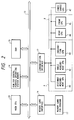
- Fig. 2 is a block diagram showing a relationship between main systems. An embodiment of the electronic survey instrument according to the present invention will be explained with reference to Figs. 1 and 2.
- the electronic survey instrument includes a battery (not shown) within a housing 10, and a main system operated with a main CPU 20.
- the electronic survey instrument also includes a distance measurement subsystem 30 acting as a measurement subsystem A to survey actually; an angle measurement subsystem 32; an inclination sensor subsystem 33; a rear display subsystem 34 acting as a display subsystem B; a front display subsystem 35; a power source subsystem 37; and the other elements.
- Two memory card insertion slots are arranged on the upper and lower portions of the electronic survey instrument.
- a key board is connected to each of the rear display subsystem 34 and the front display subsystem 35.
- the main CPU 20 which operates a main system in accordance with a distance measurement program is arranged in the main system while sub-CPUs are arranged to corresponding various subsystems.
- the sub-CPUs are connected to the main CPU 20 via a communication interface 12 so as to perform a two-way communications.
- the main CPU 20 is connected to plural sub-CPUs 40, 41 to 45, and 47 via the bus 13 and a communication interface 12.
- the single main CPU 20 is connected to the plural sub-CPUs by parallel bus lines so that it can communicate to only one sub-CPU at a time.
- a distance measurement CPU 40 for operating the distance measurement subsystem 30; an angle measurement CPU 42 for operating the angle measurement subsystem 32; an inclination CPU 43 for operating the inclination sensor subsystem 33; a rear CPU 44 for operating the rear display subsystem 34; a front CPU 45 for operating the front display subsystem 35; a power source CPU 47 for operating the power source subsystem 37; and the like.
- Each sub-CPU includes both a communication portion to the main CPU 20 and a command operation portion each operating as an operating system.
- each sub-CPU includes an application portion having both a system initializing portion and plural commands.
- a ROM 14 for a general purpose operating system memory, a RAM 15, and a memory card interface 16 for interchanging data between memory cards 17 are connected to the bus 13.
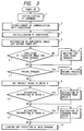
- the flow chart shows a general main routine ranging from a step that the electronic survey instrument of the present embodiment is powered on to a step that a main program is loaded and then executed.
- the hardware is first initialized (step 1). Then, whether communications between the main CPU 20 and all the subsystems are normally established is checked (step 2). All the subsystems are initialized (step 3).
- a horizontal angle saved immediately before the power source is turned off is restored in the step 4. That is, horizontal angle information is restored based on horizontal angle data immediately before a power-off time saved in a backup region of a main memory. It is originally necessary to restore both the horizontal angle and the elevation angle. However, since the elevation angle information can be obtained easily in the following step 5, only the horizontal angle information which is difficult to obtain is obtained in this step.
- a zero-point crossing of an elevation angle is awaited.
- the zero point of an elevation angle measuring encoder agrees with a reference direction, that is horizontal or vertical direction, of the optical axis of a telescope, it is necessary to perform a zero resetting operation at the reference position.
- This procedure is completed by rotating the optical axis of the telescope on the vertical plane and then resetting the count value of an encoder to zero when the telescope is agreed in the reference direction.
- the zero point crossing can be completed by rotating slightly the optical axis of the telescope.
- step 5 when it is judged that there is a zero point crossing waiting, the step 6 shown with the subroutine (to be described later) is executed. After the telescope has crossed the zero point, the process goes to the step 7. When the telescope does not cross the zero point, the process skips the step 6 but goes to the step 7.
- step 7 whether the resume process has been done at the previous power-off time is judged based on whether a resume flag is set.
- a resume flag is set, the process goes to the subroutine regarding "resume process" in the step 8.
- the resume process restores an original program counter in addition to a display immediately before a power-off time, an operational status of a subsystem, illumination and the like.
- a default drive A is set in the step 9.
- the drive A is a read-only drive formed as a ROM and stores a program that the survey instrument performs an operation necessary at a minimum.
- the drive C is a drive for having an access with the memory card 17 inserted into the memory card insertion slot 11a shown in Fig. 1. Hence, in the step 10, it is checked on whether the memory card 17 to be read with the drive C is inserted into the memory card insertion slot 11a corresponding to the drive C.
- the program from the drive C is activated in the subroutine shown in the step 11.
- the activation information for the drive B is checked in the step 12.
- the drive B is a drive that has an access with the memory card 17 inserted into the memory card insertion slot 11b.
- the program from the drive B is activated with a subroutine shown in Fig. 13.
- the main program is loaded and executed in the step 14.
- a limited time, or a maximum response waiting time to communicate the CPU 20 with subsystems, is set in the step 2-1.
- the limited time setting is made to prevent a hang-up when communication is disabled due to a failure or other causes.
- the limited time is set to 200 ms but it can be varied with an application program.
- step 2-2 when number of times retransmission, or the limited time set in the step 2-1, has passed, or abnormal data has been received, the allowable number of times retransmission is set. Setting the number of times retransmission prevents the retransmission from being endlessly repeated. In the present embodiment, the number of times the retransmission is set 16, but it can be varied in accordance with an application program.
- the maximum subsystem number is set in the step 2-3.
- Each subsystem is specified by a predetermined number. In this case, number is set to the maximum number of subsystems to be connected. In actual, six subsystems are set, including the front display subsystem 35, the rear display subsystem 34, the angle measurement subsystem 32, the inclination sensor subsystem 33, the distance measurement subsystem 30, and the power source subsystem 37.
- a data output priority is set to a specific subsystem.
- a priority is set to a subsystem with a fast data updating period to provide an improved response characteristic.
- An angle measurement subsystem which can update in about 50 ms is listed as a subsystem with a fast data updating period.
- the distance measurement subsystem updates data at about 0.5 to 3 seconds, in contrast to the angle measurement subsystem.
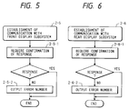
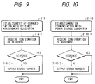
- Fig. 5 shows the subroutine for the steps 2-5.
- a response confirmation request is first made to the front display subsystem.
- communication to the front display subsystem is established and then the subsystem is terminated.
- an error number is outputted to a reference output (step 2-5-2).
- a communication output port portion is allocated as the reference output.
- the display portion may be allocated as the reference output.
- an error number is outputted to a communication output port with a small number of components and with low failure probability.
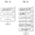
- a display buffer is first cleared in the step 3-1-1.
- a display font, an attribute, and a letter size are set in the step 3-1-2.
- An image field to be drawn is set in the next step 3-1-3. Since three physical image fields and three virtual image fields to be synthesized and displayed, it is needed to designate a specific image field to be displayed at a drawing time. Usually, a virtual image field used best of all is set as the image field to be drawn.
- an image mode displayed on the front subsystem or an image mode setting an arithmetic operation between three physical image fields, flashing, depth or the like, is performed in the step 3-1-4.
- an arithmetic operation means an operation regarding a logical product or logical sum between liquid crystal layers of three physical image fields. By performing such an operation, a suitable image is displayed as one image.
- An animation display of an icon representing "being at work” is started in the step 3-1-5.
- the display portion can display an animation image representing a waiting time independently of other controls.
- an animation mode is set to swing the image till a program activation image is actually established so that a lapse of time is displayed.
- an hourglass animated on a screen displays a lapse of time till a program activation screen is established.
- a display buffer is cleared (in the step 3-2-1) while an image mode is set (in the step 3-2-2). Since each step is same as that in Fig. 12, a detail explanation is omitted.
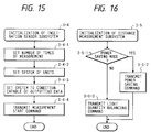
- the number of times measurement is set to obtain a data average (step 3-3-1). That is, conventionally, it has been done to eliminate errors by performing a measuring operation in an angle measurement plural number of times to obtain an average value.
- the number of times measurement is set when the main CPU 20 is activated.
- an average is calculated by performing an angle measurement 16 times for 50 ms.
- an application program can vary time and number of times.
- a unit system of output angle is set (in the step 3-3-2).
- Degree data can be outputted using as an output angle unit system in the angle measurement portion an unit system selected from degree-minute-second, GON, MIL6400, MIL600, and radian.
- the output system is set to a default unit using degree-minute-second.
- a judging requirement for stability of degree measurement value is set in the step 3-3-3.
- the degree measurement portion outputs a flag indicating a stability of degree under measuring in addition to degree data.
- a rough calculation is made in accordance with the flag to improve the response characteristic of a degree display.
- an application program can set other stable requirements.
- a data output enabling state is set in the step 3-3-4. Then, a measurement starting command is transmitted in the step 3-3-5.
- the inclination sensor subsystem is a program which process an output from an inclination sensor built in to detect the slope of a survey instrument with respect to a level direction.
- the control performed in the steps 3-3-1 and 3-3-2, is similarly performed in the steps 3-4-1 and 3-4-2.
- a data output enabling state is set and a measurement starting command is transmitted.
- the inclination sensor subsystem 33 does not set a judgment requirement because the stability of slope is not critical.
- a power saving mode is prepared therein.
- a power saving mode is usually set by turning off a power source or limiting current. Since the distance measurement procedure cannot be quickly prepared from a power saving mode, this power saving mode can be released in consideration of a response characteristic required.
- a power saving command is a command that shuts down partially or completely an operation or display in the distance measurement subsystem to reduce power consumption.
- both a digital system and an analog system in the distance measurement subsystem are shut down because of less warm-up time required. Such a power saving mode enables the power consumption of the distance measurement subsystem to halve.
- the light quantity balancing means a light quantity adjustment where an ND filter arranged in at least an external optical path or an internal optical path is adjusted to maintain a fixed relationship between the strength of light passing along the external optical path (or the optical path where light is irradiated to a distance measurement target and receives light reflected thereon) and the strength of light passing along the internal optical path (or the optical path for obtaining a reference light compared with that in the external optical path in phase).
- a record of the latest turning-off of a power source is checked (step 3-6-1).
- the main CPU 20 inspects it. If the power source has been normally cut off, end information representing that a power source has been normally turned off is recorded in the step 15-2-6-5 (to be described later). The step 3-6-1 is judged based on the end information. On the other hand, in the case where a battery is taken out carelessly without operating a power source key, the power source is cut without performing an information saving process to a memory by the resume means.
- the system is set up without any measures to restore information from a memory by the resume means, it may run away without any recovery because the memory has no information or incomplete information. In order to avoid such a runaway, it is checked whether a power source is normally cut off based on the previous power-off record.
- step 3-6-2 when when the power source has not been normally cut off at a previous stage, a resume process is suspended temporarily during a current power-on period and without being turning off the resume function itself.
- a key entry is checked (step 6-1). Usually, while a telescope waits for a zero point crossing, a title or an operation request is fixedly displayed. While there is a key entry, an adjustment is made to obtain a visible liquid crystal image or an angle of visible field (step 6-2). In concrete, a visual field angle adjusting scale is displayed to operate in accordance with a key entry operation so that a polarizing orientation can be adjusted by varying a voltage applied to a liquid crystal layer.
- a zero point crossing is checked in the following step 6-3 in any case.
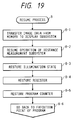
- an image content saved in a memory is transferred to the display subsystem (step 8-1) to resume an operation of the distance measurement subsystem saved (8-2).
- the illumination status saved are restored (step 8-3) and the registers saved are restored (step 8-4).
- the program counter saved in a memory is restored (step 8-5).
- the status is restored to the program execution position held immediately before a power-off time (step 8-6).
- the operational state of a subsystem and illumination are restored. Then the status is returned to the original program counter position.
- a presence of a batch command file name (for example, AUTOEXEC) is checked (step 11-1).
- Method of executing a program under MS-DOS includes a method using a command file and a method activating directly execution program. This subroutine uses the former method.
- a command file is used to activate a user program so that the existence of the command file is first checked.
- step 11-1 confirms the existence of the batch command file
- a user program "AUTOEXEC. BAT” is loaded and executed (step 11-2).
- step 11-1 does not confirm the existence of a batch command file
- the existence of an execution program for example, USRMAIN
- step 11-3 the existence of an execution program
- USRMAIN the existence of an execution program
- step 11-5 the execution of a menu definition file "MAIN. CNF" is checked (step 11-5).
- the existence of a batch command file is confirmed in the step 11-1 and the existence of an execution program is confirmed in the step 11-3, all post-processes are shifted to an application program. Therefore, when a user tries to make a simple program and to execute it, he has to make all program selection menus or the like by himself.
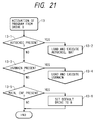
- program activation from drive B subroutine shown in the step 13 is shown in Fig. 21. Since the subroutine shown in Fig. 21 is similar to "program activation from drive C" subroutine shown in Fig. 20, a detail explanation for it will be omitted.
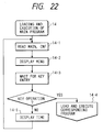
- step 14 "load and execution of main program" in the step 14 is executed in the case the default drive is set to A (step 9), the activation information for the drive C is checked (step 10), and the activation information of drive B is checked (step 12).
- the main program is loaded and executed with the default drive set to A.
- the main program is loaded and executed in the step 14 when the subroutine shown in Fig. 20 or 21 has been ended while any drives register no user programs and the default drive is set to C or B in the step 11-6.
- a menu is displayed (step 14-2) to sustain a key entry waiting state (step 14-3).
- a menu number or ENT is inputted through a key operation, the corresponding program is loaded and executed (step 14-4).
- step 14-5 time is displayed (step 14-5) and then the status returns to the step 14-1.
- the time is continuously displayed till a key entry allows the step 14-4.
- the key entry process generally means a process that a keyboard entry calls back a status from a program.
- a key operation is made to cut off a power source
- the system automatically returns to a power-off state as a matter of course.
- the power-off process is automatically performed with no key entry. Building a power source keying process in a key entry process routine releases a programmer who makes an application program from the troublesome power source keying process so that it is prevented that a power-off process is activated at a risky timing.
- a series of routine in the key entry process includes an automatic power-cut-off process.
- the status of a power source key is obtained in the step 15-1 to judge that the power source key has been depressed for a power-off process.
- the power-off process in the step 15-2 is executed.
- step 15-3 If a power-off process has been completed or a power-off process is not forcibly executed by depressing down a power source key, an automatic cutoff checking is then performed (step 15-3). That is, when the automatic cut-off is in an on state, an automatic cut-off process is executed in the step 15-4 (to be described later). If an automatic cut-off process has been completed or an automatic cut-off process is not in an on state, a key entry is checked in the step 15-5. When there is a key entry, an input key code is obtained (step 15-6) to set a presence of a key inputting (step 15-7). When there is no key entry, no key entry is set (step 15-8).
- an image content displayed currently is saved into a backup memory for a main memory (step 15-2-1).
- a power-off message is displayed on the display screen (step 15-2-2) to bring to a key entry waiting state (step 15-2-3).
- an operable key includes a power saving key, a reset key, a power-off key, and an escape key.
- step 15-2-5 When the power-off key is depressed, a shutdown process is executed (step 15-2-6). When the escape key is depressed, a power-off mode is canceled (step 15-2-7).
- idle time or time during which no key operation is done continuously (or time during which a variation in degree is not detected), is accumulated.
- the idle time properly preset is between one to sixty minutes.
- an automatic cut-off condition is judged and then it is judged whether the automatic cut-off process should be performed (step 15-4-2).
- the automatic cut-off condition is that time accumulated in the step 15-4-1 has reached a preset idle time and a distance measurement is not under operation.
- a shutdown process is executed in the step 15-2-6. This shutdown process is similar to the shutdown process in "power-off process" in the step 15-2.
- power saving mode process is prepared in the subroutine for "power-off process", but may be prepared as an independent process.
- the power saving mode process can be prepared to all subsystems.
- step 15-2-4-1 the status of all subsystems and devices by which a power source can be controlled is stored in a backup memory for a main memory.
- steps 15-2-4-2 the subsystems and devices are shifted to a power saving mode. Thereafter, a message representing "being on a power saving" is displayed (step 15-2-4-3), the status is maintained till a key is depressed (step 15-2-4-4).
- step 15-2-4-5 the power saving message is erased (step 15-2-4-6).
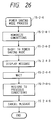
- step 15-2-6 the shutdown process in the steps 15-2 and 15-4 (step 15-2-6) will be explained in accordance with the subroutine shown in Fig. 27.
- a current horizontal angle display value is first held (step 15-2-6-1).
- a presence or absence of a resume is checked (step 15-2-6-2).
- a file in an open state is closed (step 15-2-6-3).
- resume recommencement information is stored (step 15-2-6-4). That is, an image immediately before a power source is cut off, an operation state of a subsystem, illumination, a program counter, and the like are saved into a memory.
- step 15-2-6-5 After resume information is stored in the step 15-2-6-4 or a file opened in the step 15-2-6-3 is closed, the information that a power-off operation has been normally done is stored as end information (step 15-2-6-5).
- This end information is checked in the step 3-6-1.
- the resume means restores information saved in a memory in the step 8.
- step 15-2-6 If a power source should be unexpectedly cut off, for example, by carelessly taking out a battery, the power-off process in the step 15-2-6 cannot be executed as a matter of course. In this case, a resume flag is canceled in the step 3-6-2 so that the status cannot be go to the step 8. After the step 15-2-6-5 has ended, the power source is cut off.
Landscapes
- Engineering & Computer Science (AREA)
- Physics & Mathematics (AREA)
- General Physics & Mathematics (AREA)
- Theoretical Computer Science (AREA)
- Radar, Positioning & Navigation (AREA)
- Remote Sensing (AREA)
- General Engineering & Computer Science (AREA)
- Power Sources (AREA)
- Arrangements For Transmission Of Measured Signals (AREA)
- Instructional Devices (AREA)
Applications Claiming Priority (2)
| Application Number | Priority Date | Filing Date | Title |
|---|---|---|---|
| JP91031/93 | 1993-04-19 | ||
| JP5091031A JPH06300560A (ja) | 1993-04-19 | 1993-04-19 | 電子式測量機 |
Publications (2)
| Publication Number | Publication Date |
|---|---|
| EP0621458A1 true EP0621458A1 (fr) | 1994-10-26 |
| EP0621458B1 EP0621458B1 (fr) | 1998-08-12 |
Family
ID=14015156
Family Applications (1)
| Application Number | Title | Priority Date | Filing Date |
|---|---|---|---|
| EP94106074A Expired - Lifetime EP0621458B1 (fr) | 1993-04-19 | 1994-04-19 | Instrument d'arpentage électronique |
Country Status (4)
| Country | Link |
|---|---|
| US (1) | US5519642A (fr) |
| EP (1) | EP0621458B1 (fr) |
| JP (1) | JPH06300560A (fr) |
| DE (1) | DE69412330T2 (fr) |
Cited By (1)
| Publication number | Priority date | Publication date | Assignee | Title |
|---|---|---|---|---|
| US8645738B2 (en) | 2009-10-27 | 2014-02-04 | Nokia Corporation | Nonvolatile device |
Families Citing this family (14)
| Publication number | Priority date | Publication date | Assignee | Title |
|---|---|---|---|---|
| JPH09304074A (ja) * | 1996-03-11 | 1997-11-28 | Asahi Optical Co Ltd | 電子測量機 |
| US6182372B1 (en) * | 1998-08-25 | 2001-02-06 | Trimble Navigation Limited | Interpolation using digital means for range findings in a total station |
| JP2000249550A (ja) * | 1999-03-01 | 2000-09-14 | Asahi Precision Co Ltd | 電子測量機用電源装置 |
| US6873406B1 (en) * | 2002-01-11 | 2005-03-29 | Opti-Logic Corporation | Tilt-compensated laser rangefinder |
| US20030220831A1 (en) * | 2002-05-21 | 2003-11-27 | Lifevine, Inc. | System and method of collecting surveys remotely |
| US7603804B2 (en) * | 2003-11-04 | 2009-10-20 | Leupold & Stevens, Inc. | Ballistic reticle for projectile weapon aiming systems and method of aiming |
| US7239377B2 (en) | 2004-10-13 | 2007-07-03 | Bushnell Performance Optics | Method, device, and computer program for determining a range to a target |
| TWI429875B (zh) | 2005-11-01 | 2014-03-11 | Leupold & Stevens Inc | 用於傾斜射擊之彈道測距方法及系統 |
| US7658031B2 (en) * | 2005-12-21 | 2010-02-09 | Bushnell, Inc. | Handheld rangefinder operable to determine hold over ballistic information |
| US7684017B2 (en) | 2006-10-26 | 2010-03-23 | Callaway Golf Company | Laser range finder for use on a golf course |
| US8081298B1 (en) | 2008-07-24 | 2011-12-20 | Bushnell, Inc. | Handheld rangefinder operable to determine hold-over ballistic information |
| JP6025696B2 (ja) * | 2013-11-28 | 2016-11-16 | 京セラドキュメントソリューションズ株式会社 | 電子機器 |
| JP6625357B2 (ja) * | 2015-07-17 | 2019-12-25 | オリンパス株式会社 | 内視鏡装置 |
| CN111201406B (zh) * | 2017-10-11 | 2021-08-24 | 夏普株式会社 | 空调机以及网络系统 |
Citations (2)
| Publication number | Priority date | Publication date | Assignee | Title |
|---|---|---|---|---|
| GB2229822A (en) * | 1989-03-31 | 1990-10-03 | Sokkisha | Surveying apparatus |
| EP0415376A2 (fr) * | 1989-08-28 | 1991-03-06 | Kabushiki Kaisha Toshiba | Ordinateur avec fonction de reprise |
Family Cites Families (5)
| Publication number | Priority date | Publication date | Assignee | Title |
|---|---|---|---|---|
| US3417394A (en) * | 1967-02-20 | 1968-12-17 | Elgeo Instr Of America Inc | Geodetic instrument |
| US4327410A (en) * | 1980-03-26 | 1982-04-27 | Ncr Corporation | Processor auto-recovery system |
| US4948138A (en) * | 1982-12-06 | 1990-08-14 | Igt | Device for maintaining game state audit trail upon instantaneous power failure |
| US5291262A (en) * | 1989-03-27 | 1994-03-01 | Dunne Jeremy G | Laser surveying instrument |
| US4999575A (en) * | 1989-09-25 | 1991-03-12 | General Electric Company | Power supply and monitor for controlling an electrical load following a power outage |
-
1993
- 1993-04-19 JP JP5091031A patent/JPH06300560A/ja active Pending
-
1994
- 1994-04-19 EP EP94106074A patent/EP0621458B1/fr not_active Expired - Lifetime
- 1994-04-19 US US08/229,794 patent/US5519642A/en not_active Expired - Fee Related
- 1994-04-19 DE DE69412330T patent/DE69412330T2/de not_active Expired - Fee Related
Patent Citations (2)
| Publication number | Priority date | Publication date | Assignee | Title |
|---|---|---|---|---|
| GB2229822A (en) * | 1989-03-31 | 1990-10-03 | Sokkisha | Surveying apparatus |
| EP0415376A2 (fr) * | 1989-08-28 | 1991-03-06 | Kabushiki Kaisha Toshiba | Ordinateur avec fonction de reprise |
Cited By (1)
| Publication number | Priority date | Publication date | Assignee | Title |
|---|---|---|---|---|
| US8645738B2 (en) | 2009-10-27 | 2014-02-04 | Nokia Corporation | Nonvolatile device |
Also Published As
| Publication number | Publication date |
|---|---|
| US5519642A (en) | 1996-05-21 |
| DE69412330D1 (de) | 1998-09-17 |
| JPH06300560A (ja) | 1994-10-28 |
| DE69412330T2 (de) | 1999-03-18 |
| EP0621458B1 (fr) | 1998-08-12 |
Similar Documents
| Publication | Publication Date | Title |
|---|---|---|
| EP0621458B1 (fr) | Instrument d'arpentage électronique | |
| US6594723B1 (en) | Method and apparatus for updating data in nonvolatile memory | |
| US6327653B1 (en) | Technique for easily changing operating systems of a digital computer system using at least two pushbuttons | |
| US5903766A (en) | Suspend/resume capability for a protected mode microprocessor | |
| EP0230351B1 (fr) | Système de traitement d'information | |
| EP3690653A1 (fr) | Récupération et mise à jour du bios | |
| US8230210B1 (en) | Interactive firmware recovery | |
| KR100381416B1 (ko) | 컴퓨터 시스템 및 그 컴퓨터 시스템의 프로덕트 키 저장방법 | |
| US20050027957A1 (en) | Apparatus and method for control of write filter | |
| JP3978521B2 (ja) | 遊技機 | |
| EP0576027A2 (fr) | Ordinateur portable réalisant la sélection des fonctions avec des icônes | |
| EP0247605B1 (fr) | Dispositif de gestion de système pour système à multiprocesseur | |
| EP0430219A2 (fr) | Procédé et système de commande de procedure de reprise dans une unité de calculateur capable de connecter une unité d'extension | |
| US6553400B1 (en) | Suspend and resume processing method for suspending and resuming a plurality of states of programmed operations | |
| US7149885B2 (en) | Automatic concealment of expansion cards in computer system | |
| US20090138865A1 (en) | Performing an operating system upgrade without multiple system interruptions | |
| KR200258404Y1 (ko) | 컴퓨터용하드디스크내자료보호및복원장치 | |
| CN114398065B (zh) | 微前端系统更新方法、装置、电子设备及存储介质 | |
| JPH10268981A (ja) | コンピュータシステムの電源遮断装置及び方法 | |
| JP2003131896A (ja) | 情報処理装置、再起動方法及び再起動プログラム | |
| JP4418942B2 (ja) | 遊技機 | |
| JP2003330724A (ja) | 情報処理装置、情報処理方法、及びプログラム | |
| JP3064823B2 (ja) | データ処理装置 | |
| JPH05241796A (ja) | 端末装置のインストール方法 | |
| KR100473489B1 (ko) | 멀티미디어 공중단말기의 데이터 관리방법 |
Legal Events
| Date | Code | Title | Description |
|---|---|---|---|
| PUAI | Public reference made under article 153(3) epc to a published international application that has entered the european phase |
Free format text: ORIGINAL CODE: 0009012 |
|
| AK | Designated contracting states |
Kind code of ref document: A1 Designated state(s): CH DE FR LI SE |
|
| 17P | Request for examination filed |
Effective date: 19950323 |
|
| 17Q | First examination report despatched |
Effective date: 19961014 |
|
| GRAG | Despatch of communication of intention to grant |
Free format text: ORIGINAL CODE: EPIDOS AGRA |
|
| GRAG | Despatch of communication of intention to grant |
Free format text: ORIGINAL CODE: EPIDOS AGRA |
|
| GRAH | Despatch of communication of intention to grant a patent |
Free format text: ORIGINAL CODE: EPIDOS IGRA |
|
| GRAH | Despatch of communication of intention to grant a patent |
Free format text: ORIGINAL CODE: EPIDOS IGRA |
|
| GRAA | (expected) grant |
Free format text: ORIGINAL CODE: 0009210 |
|
| AK | Designated contracting states |
Kind code of ref document: B1 Designated state(s): CH DE FR LI SE |
|
| REG | Reference to a national code |
Ref country code: CH Ref legal event code: NV Representative=s name: BOVARD AG PATENTANWAELTE Ref country code: CH Ref legal event code: EP |
|
| REF | Corresponds to: |
Ref document number: 69412330 Country of ref document: DE Date of ref document: 19980917 |
|
| ET | Fr: translation filed | ||
| PLBI | Opposition filed |
Free format text: ORIGINAL CODE: 0009260 |
|
| PLBF | Reply of patent proprietor to notice(s) of opposition |
Free format text: ORIGINAL CODE: EPIDOS OBSO |
|
| 26 | Opposition filed |
Opponent name: CARL ZEISS JENA GMBH Effective date: 19990508 |
|
| PLBF | Reply of patent proprietor to notice(s) of opposition |
Free format text: ORIGINAL CODE: EPIDOS OBSO |
|
| PLBF | Reply of patent proprietor to notice(s) of opposition |
Free format text: ORIGINAL CODE: EPIDOS OBSO |
|
| PLBP | Opposition withdrawn |
Free format text: ORIGINAL CODE: 0009264 |
|
| PLBD | Termination of opposition procedure: decision despatched |
Free format text: ORIGINAL CODE: EPIDOSNOPC1 |
|
| PLBM | Termination of opposition procedure: date of legal effect published |
Free format text: ORIGINAL CODE: 0009276 |
|
| STAA | Information on the status of an ep patent application or granted ep patent |
Free format text: STATUS: OPPOSITION PROCEDURE CLOSED |
|
| 27C | Opposition proceedings terminated |
Effective date: 20031026 |
|
| PGFP | Annual fee paid to national office [announced via postgrant information from national office to epo] |
Ref country code: SE Payment date: 20050406 Year of fee payment: 12 |
|
| PGFP | Annual fee paid to national office [announced via postgrant information from national office to epo] |
Ref country code: FR Payment date: 20050408 Year of fee payment: 12 |
|
| PGFP | Annual fee paid to national office [announced via postgrant information from national office to epo] |
Ref country code: DE Payment date: 20050414 Year of fee payment: 12 |
|
| PGFP | Annual fee paid to national office [announced via postgrant information from national office to epo] |
Ref country code: CH Payment date: 20050415 Year of fee payment: 12 |
|
| PG25 | Lapsed in a contracting state [announced via postgrant information from national office to epo] |
Ref country code: SE Free format text: LAPSE BECAUSE OF NON-PAYMENT OF DUE FEES Effective date: 20060420 |
|
| PG25 | Lapsed in a contracting state [announced via postgrant information from national office to epo] |
Ref country code: LI Free format text: LAPSE BECAUSE OF NON-PAYMENT OF DUE FEES Effective date: 20060430 Ref country code: CH Free format text: LAPSE BECAUSE OF NON-PAYMENT OF DUE FEES Effective date: 20060430 |
|
| PG25 | Lapsed in a contracting state [announced via postgrant information from national office to epo] |
Ref country code: DE Free format text: LAPSE BECAUSE OF NON-PAYMENT OF DUE FEES Effective date: 20061101 |
|
| REG | Reference to a national code |
Ref country code: CH Ref legal event code: PL |
|
| EUG | Se: european patent has lapsed | ||
| REG | Reference to a national code |
Ref country code: FR Ref legal event code: ST Effective date: 20061230 |
|
| PG25 | Lapsed in a contracting state [announced via postgrant information from national office to epo] |
Ref country code: FR Free format text: LAPSE BECAUSE OF NON-PAYMENT OF DUE FEES Effective date: 20060502 |