EP0621492B1 - Verfahren zur Strahlungskeulenkompression in Antennendiagrammen - Google Patents
Verfahren zur Strahlungskeulenkompression in Antennendiagrammen Download PDFInfo
- Publication number
- EP0621492B1 EP0621492B1 EP94301787A EP94301787A EP0621492B1 EP 0621492 B1 EP0621492 B1 EP 0621492B1 EP 94301787 A EP94301787 A EP 94301787A EP 94301787 A EP94301787 A EP 94301787A EP 0621492 B1 EP0621492 B1 EP 0621492B1
- Authority
- EP
- European Patent Office
- Prior art keywords
- signal
- antenna
- antennas
- antenna system
- difference signal
- Prior art date
- Legal status (The legal status is an assumption and is not a legal conclusion. Google has not performed a legal analysis and makes no representation as to the accuracy of the status listed.)
- Expired - Lifetime
Links
- 238000000034 method Methods 0.000 title claims description 16
- 238000007906 compression Methods 0.000 title description 24
- 230000006835 compression Effects 0.000 title description 22
- 230000005540 biological transmission Effects 0.000 description 8
- 238000007796 conventional method Methods 0.000 description 5
- 238000010586 diagram Methods 0.000 description 5
- 238000004088 simulation Methods 0.000 description 5
- 230000000694 effects Effects 0.000 description 2
- 238000004364 calculation method Methods 0.000 description 1
- 230000005855 radiation Effects 0.000 description 1
Images


Classifications
-
- H—ELECTRICITY
- H01—ELECTRIC ELEMENTS
- H01Q—ANTENNAS, i.e. RADIO AERIALS
- H01Q25/00—Antennas or antenna systems providing at least two radiating patterns
- H01Q25/02—Antennas or antenna systems providing at least two radiating patterns providing sum and difference patterns
-
- G—PHYSICS
- G01—MEASURING; TESTING
- G01S—RADIO DIRECTION-FINDING; RADIO NAVIGATION; DETERMINING DISTANCE OR VELOCITY BY USE OF RADIO WAVES; LOCATING OR PRESENCE-DETECTING BY USE OF THE REFLECTION OR RERADIATION OF RADIO WAVES; ANALOGOUS ARRANGEMENTS USING OTHER WAVES
- G01S13/00—Systems using the reflection or reradiation of radio waves, e.g. radar systems; Analogous systems using reflection or reradiation of waves whose nature or wavelength is irrelevant or unspecified
- G01S13/02—Systems using reflection of radio waves, e.g. primary radar systems; Analogous systems
- G01S13/06—Systems determining position data of a target
- G01S13/42—Simultaneous measurement of distance and other co-ordinates
- G01S13/44—Monopulse radar, i.e. simultaneous lobing
- G01S13/4409—HF sub-systems particularly adapted therefor, e.g. circuits for signal combination
-
- G—PHYSICS
- G01—MEASURING; TESTING
- G01S—RADIO DIRECTION-FINDING; RADIO NAVIGATION; DETERMINING DISTANCE OR VELOCITY BY USE OF RADIO WAVES; LOCATING OR PRESENCE-DETECTING BY USE OF THE REFLECTION OR RERADIATION OF RADIO WAVES; ANALOGOUS ARRANGEMENTS USING OTHER WAVES
- G01S13/00—Systems using the reflection or reradiation of radio waves, e.g. radar systems; Analogous systems using reflection or reradiation of waves whose nature or wavelength is irrelevant or unspecified
- G01S13/87—Combinations of radar systems, e.g. primary radar and secondary radar
-
- G—PHYSICS
- G01—MEASURING; TESTING
- G01S—RADIO DIRECTION-FINDING; RADIO NAVIGATION; DETERMINING DISTANCE OR VELOCITY BY USE OF RADIO WAVES; LOCATING OR PRESENCE-DETECTING BY USE OF THE REFLECTION OR RERADIATION OF RADIO WAVES; ANALOGOUS ARRANGEMENTS USING OTHER WAVES
- G01S7/00—Details of systems according to groups G01S13/00, G01S15/00, G01S17/00
- G01S7/02—Details of systems according to groups G01S13/00, G01S15/00, G01S17/00 of systems according to group G01S13/00
- G01S7/28—Details of pulse systems
- G01S7/2813—Means providing a modification of the radiation pattern for cancelling noise, clutter or interfering signals, e.g. side lobe suppression, side lobe blanking, null-steering arrays
Definitions
- the present invention relates to a method of performing beam compression of radar antenna patterns, which can provide better performances in the beam compression process of an antenna pattern of a radar including a monopulse power feed system.
- the beam width is one of the indexes representing the performance of an antenna pattern of a receiving antenna or other type antennas.
- a narrower beam width in an antenna pattern will give a better performance.
- an antenna for a radar system if it is desired to double the ability or the resolution to discriminate objects, it is required to halve the beam width and thus it is required to double the size of the antenna.
- the doubling of the size leads to not only a larger occupied region but also various disadvantages such as an increase in the weight of the antenna and in the size of a structure for supporting the antenna.
- the size of an antenna is halved, then the beam width will be doubled and the discrimination ability will be degraded by a factor of two.
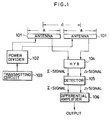
- FIG. 1 of the accompanying drawings is a schematic diagram illustrating a radar system which can perform beam compression in such a manner described above.
- reference numerals 101, 101 designate a pair of antennas with a monopulse power feed system, wherein each antenna has a length of a, and the center-to-center distance between the antennas is d.
- Reference numeral 102 designates a power divider and reference numeral 103 designates a transmission circuit.
- the transmission circuit 103 generates the transmission power, which is fed in the same phase to the antennas 101 via the power divider 102.
- Reference numeral 104 designates a hybrid circuit which produces a sum signal ⁇ and a difference signal ⁇ from receiving signals of the two antennas 101, 101.
- Reference numeral 105 designates a detector for detecting the sum signal ⁇ and the difference signal ⁇ , and reference numeral 106 designates a differential amplifier which provides an antenna output signal by subtracting the difference signal ⁇ from the sum signal ⁇ .
- the differential amplifier 106 provides the antenna output signal produced by subtracting the difference signal ⁇ from the sum signal ⁇ .
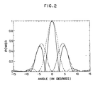
- One aspect of the antenna output signal is shown in Figure 2 in a general representing manner of a power pattern associated with beam compression. That is, in Figure 2, the broken line represents the sum signal ⁇ of the receiving signals of the two antennas, and the alternate long and short dash line represents the difference signal ⁇ . The solid line represents the output signal ( ⁇ - ⁇ ) which is the difference between these two signals. As can be seen, the output signal shows a synthetic directional characteristic having a compressed beam width.
- a radar system which performs beam compression according to the conventional technique as described above is disclosed for instance in document US 2 567 197 or DE 1 791 200 and can provide a certain degree of beam compression.
- the difference signal ⁇ will become small compared to the sum signal ⁇ .
- the final output signal value obtained by subtracting the difference signal ⁇ from the sum signal ⁇ will have only a slight difference from the value of the sum signal ⁇ . This means that there is a problem that efficient effects of beam compression cannot be achieved.
- the present invention provides a method for compressing the beam width of the antenna pattern of a radar system , comprising the steps of: providing a radar antenna system comprising two similar antennas having a monopulse feed system; scanning the antenna system while transmitting radio waves from the two antennas of the antenna system in such a manner that both the radio waves transmitted from the respective antennas are in the same phase; receiving by the antenna system the radio waves which were transmitted from the antenna system and reflected by a scattering object and have finally come back; producing a sum signal and a difference signal of the received signals of the two antennas of the antenna system; and performing signal processing : comprising the steps of subtracting the difference signal from the sum signal and providing the resulting signal as a final antenna output signal; the method being characterized in that the above-described signal processing step further comprises the step of providing the final antenna output signal only if the double differential coefficient of the receiving pattern waveform associated with the sum signal is negative and further if the double differential coefficient of the receiving pattern waveform associated with the difference signal is positive
- the receiving pattern waveform has an upwardly convex form near the angle at which an object exists, whereas it does not have an upwardly convex form near the angles at which no object exists.
- the receiving pattern waveform associated with the sum signal has an upwardly convex form near the angle at which an object exists as represented by the broken line in Figure 2.
- the receiving pattern waveform associated with the difference signal has a downwardly convex form near the angle at which an object exists, and the waveform gradually changes to an upwardly convex form as the angle departs from that at which the object exist, as represented by the alternate long and short dash line in Figure 2.
- the receiving pattern waveform associated with the sum signal has an upwardly convex form, that is, its double differential coefficient is negative, and furthermore if the receiving pattern waveform associated with the difference signal has a downwardly convex form, that is, its double differential coefficient is positive, is the signal which is produced by subtracting the difference signal from the sum signal provided as the output signal, a zero output signal being provided if the above conditions are not satisfied.
- the output signal is provided only in the regions where the receiving pattern waveform associated with the sum signal represented by the broken line in the power pattern of Figure 2 has an upwardly convex form and the receiving pattern waveform associated with the difference signal represented by the alternate long and short dash line has a downwardly convex form.
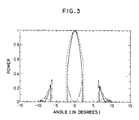
- the output signal is provided in such a manner as represented by the solid line in Figure 3, which shows a significant improvement in the beam compression effect.
- the broken lines represent the regions where the receiving pattern waveform associated with the sum signal has an upwardly convex form
- the alternate long and short dash lines represent the regions where the receiving pattern waveform associated with the difference signal has a downwardly convex form.
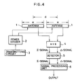
- FIG 4 is a simplified diagram showing the configuraiton of a radar system for use in explaining a method of beam compression in the antenna pattern of a radar system according to one embodiment of the present invention.
- reference numerals 1, 1 designate two transmitting/receiving antennas of an antenna system, each antenna having the same structure, such as a horn antenna or an array antenna with a monopulse feed system, wherein each antenna has a length of "a", and the center-to-center distance between the antennas is d.
- Reference numeral 2 designates a power divider and reference numeral 3 designates a transmission circuit.
- the transmission circuit 3 generates transmission power, which is fed in the same phase to the antennas 1, 1 via the power divider 2.
- Reference numeral 4 designates a hybrid circuit which produces a sum signal ⁇ and a difference signal ⁇ from receiving signals of the two antennas 1, 1.
- Reference numeral 5 designates a detector, and reference numeral 6 designates a signal processing unit for providing an output signal which is produced by subtracting the difference signal ⁇ from the sum signal ⁇ if the receiving pattern waveform associated with the sum signal ⁇ detected by the detector 5 has an upwardly convex form, that is, its double differential coefficient is negative and if the receiving pattern waveform associated with the difference signal ⁇ has a downwardly convex form, that is, its double differential coefficient is positive, but providing a zero output signal if the above conditions are not satisfied.
- the transmission circuit 3 provides transmission power via the power divider 2 to the antenna system comprising the antennas 1, 1, then the antenna system scans the antenna beam while transmitting radio waves.
- the transmitted radio wave has come back after it was reflected by a scattering object, it is received by the antennas 1, 1 and then it is input to the hybrid circuit 4 which in turn provides a sum signal ⁇ corresponding to a sum signal pattern and also provides a difference signal ⁇ corresponding to a difference signal pattern.
- These sum signal ⁇ and difference signal ⁇ are detected by the detector 5, and then subjected to the above-described signal processing in the signal processing unit 6 so as to provide an output corresponding to an antenna pattern having improved beam compression characteristics.
- Figure 5 shows the result of simulation on the radar system shown in Figure 4 wherein the simulation was done assuming that the antenna system is configured with uniformly distributed horn antennas 1, 1 having a length "a" which is five times the wavelength of the receiving radio wave and wherein the center-to-center distance between the antennas is 1.04 times the antenna length a.
- This simulation result shows the final output power pattern obtained under the condition that there are point scattering objects,-which are electromagnetically equivalent to each other, in the directions of -12° , -6° , 0° , 6° , and 12° about the rotation axis of the antenna system, wherein all the scattering objects exist at the same distance from the antenna system.
- Figure 6 shows a final output power pattern obtained in the radar system shown in Figure 1 using a conventional method of beam compression.
- the method of beam compression according to the present invention can provide a final output pattern waveform having good consistency with the distribution of scattering objects even under the conditions where the conventional beam compression method results in a final output pattern waveform having great inconsistency with the distribution of scattering objects, which means that the present invention can provide more effective beam compression than the conventional method.
- Figure 7 shows a specific example of the configuration of the antenna system of the radar system shown in Figure 4.
- the antenna system comprises horn antennas 11, 11 having the same structure, and an element 12 for supporting the antennas.
- the signal processing unit 6 shown in Figure 4 may be configured by using known means or techniques in such a manner that after a receiving signal is converted to a digital signal by an analog-to-digital (A/D) converter, the calculation of a double differential coefficient, the decision on this double differential coefficient, and the subtraction are performed by a computer.
- Figure 8 shows an example of such a configuration.
- reference numerals 21 and 22 designate analog-to-digital (A/D) converters which respectively convert the analog sum signal ⁇ and difference signal ⁇ detected by the detector into digital values.
- Reference numeral 23 is a computer which calculates the double differential coefficients of the sum signal ⁇ and the difference signal ⁇ , and determines the sign of the calculated values and further outputs either a value obtained by subtracting the difference signal ⁇ from the sum signal ⁇ or a zero value.
- the final output signal is actually output only if the receiving pattern waveform associated with the sum signal has an upwardly convex form, that is, its double differential coefficient is negative and further if the receiving pattern waveform associated with the difference signal has a downwardly convex form, that is, its double differential coefficient is positive, whereby more effective beam compression can be achieved.
Landscapes
- Engineering & Computer Science (AREA)
- Radar, Positioning & Navigation (AREA)
- Remote Sensing (AREA)
- Computer Networks & Wireless Communication (AREA)
- Physics & Mathematics (AREA)
- General Physics & Mathematics (AREA)
- Radar Systems Or Details Thereof (AREA)
Claims (1)
- Verfahren zur Kompression der Keulenbreite des Antennendiagramms eines Radarsystems, umfassend die folgenden Schritte: Bereitstellen eines Radarantennensystems, das zwei ähnliche Antennen (1,1) mit einem Monopuls-Stromspeisesystem aufweist; Abtasten des genannten Antennensystems während des Sendens von Funkwellen von den genannten beiden Antennen des Antennensystems auf eine solche Weise, daß beide von den jeweiligen Antennen gesendeten Funkwellen gleichphasig sind; Empfangen derjenigen Funkwellen mit dem Antennensystem, die von dem genannten Antennensystem gesendet und durch verstreute Objekte reflektiert wurden und schließlich zu dem genannten Antennensystem zurückgekommen sind; Erzeugen eines Summensignals und eines Differenzsignals der empfangenen Signale der genannten beiden Antennen des Antennensystems; und Durchführen einer Signalverarbeitung, umfassend die folgenden Schritte: Subtrahieren des genannten Differenzsignals von dem genannten Summensignal und Bereitstellen des resultierenden Signals als endgültiges Antennenausgangssignal: wobei das genannte Verfahren dadurch gekennzeichnet ist, daß der genannte Signalverarbeitungsschritt ferner den Schritt umfaßt, daß das genannte endgültige Antennenausgangssignal nur dann bereitgestellt wird, wenn der doppelte Differentialkoeffizient der Empfangsdiagramm-Wellenform in Zusammenhang mit dem genannten Summensignal negativ ist, und ferner dann, wenn der doppelte Differentialkoeffizient der Empfangsdiagramm-Wellenform in Zusammenhang mit dem genannten Differenzsignal positiv ist, aber ein Null-Ausgangssignal bereitgestellt wird, wenn die obigen Bedingungen nicht erfüllt sind.
Applications Claiming Priority (2)
| Application Number | Priority Date | Filing Date | Title |
|---|---|---|---|
| JP5117575A JP2544292B2 (ja) | 1993-04-22 | 1993-04-22 | レ―ダにおけるアンテナパタ―ンのビ―ム圧縮処理方法 |
| JP117575/93 | 1993-04-22 |
Publications (2)
| Publication Number | Publication Date |
|---|---|
| EP0621492A1 EP0621492A1 (de) | 1994-10-26 |
| EP0621492B1 true EP0621492B1 (de) | 1997-12-17 |
Family
ID=14715221
Family Applications (1)
| Application Number | Title | Priority Date | Filing Date |
|---|---|---|---|
| EP94301787A Expired - Lifetime EP0621492B1 (de) | 1993-04-22 | 1994-03-14 | Verfahren zur Strahlungskeulenkompression in Antennendiagrammen |
Country Status (4)
| Country | Link |
|---|---|
| US (1) | US5432519A (de) |
| EP (1) | EP0621492B1 (de) |
| JP (1) | JP2544292B2 (de) |
| DE (1) | DE69407332T2 (de) |
Families Citing this family (38)
| Publication number | Priority date | Publication date | Assignee | Title |
|---|---|---|---|---|
| US5569373A (en) * | 1995-06-28 | 1996-10-29 | Smith; Gerald F. | Reusable fluid filter and adapter |
| US6488848B1 (en) | 2000-04-24 | 2002-12-03 | Vortex International, Llc | Cleanable filter with ported cylinder adjacent screen |
| US6818125B2 (en) * | 2000-04-24 | 2004-11-16 | Vortex International, Llc | Engine block with angled oil outlets |
| US6540914B1 (en) | 2000-04-24 | 2003-04-01 | Vortex International, Llc | Cleanable filter with spinning screen |
| US6666968B2 (en) | 2001-03-22 | 2003-12-23 | Vortex International, Llc | Fluid filtration apparatus |
| JP4093792B2 (ja) * | 2002-04-18 | 2008-06-04 | 富士通株式会社 | 移動無線局の位置を決定する測位システム、プログラムおよび位置決定方法 |
| US20040079401A1 (en) * | 2002-10-24 | 2004-04-29 | Smith Gerald F. | Re-useable filter cleaning apparatus |
| US7929914B2 (en) * | 2004-03-31 | 2011-04-19 | The Invention Science Fund I, Llc | Mote networks using directional antenna techniques |
| US8275824B2 (en) * | 2004-03-31 | 2012-09-25 | The Invention Science Fund I, Llc | Occurrence data detection and storage for mote networks |
| US20060004888A1 (en) * | 2004-05-21 | 2006-01-05 | Searete Llc, A Limited Liability Corporation Of The State Delaware | Using mote-associated logs |
| US7389295B2 (en) * | 2004-06-25 | 2008-06-17 | Searete Llc | Using federated mote-associated logs |
| WO2005099233A2 (en) * | 2004-03-31 | 2005-10-20 | Searete Llc | Transmission of mote-associated index data |
| US8346846B2 (en) * | 2004-05-12 | 2013-01-01 | The Invention Science Fund I, Llc | Transmission of aggregated mote-associated log data |
| US7457834B2 (en) * | 2004-07-30 | 2008-11-25 | Searete, Llc | Aggregation and retrieval of network sensor data |
| US7599696B2 (en) * | 2004-06-25 | 2009-10-06 | Searete, Llc | Frequency reuse techniques in mote-appropriate networks |
| US20050255841A1 (en) * | 2004-05-12 | 2005-11-17 | Searete Llc | Transmission of mote-associated log data |
| US7941188B2 (en) | 2004-03-31 | 2011-05-10 | The Invention Science Fund I, Llc | Occurrence data detection and storage for generalized sensor networks |
| US20050227686A1 (en) * | 2004-03-31 | 2005-10-13 | Jung Edward K Y | Federating mote-associated index data |
| US9062992B2 (en) * | 2004-07-27 | 2015-06-23 | TriPlay Inc. | Using mote-associated indexes |
| US7366544B2 (en) * | 2004-03-31 | 2008-04-29 | Searete, Llc | Mote networks having directional antennas |
| US7317898B2 (en) * | 2004-03-31 | 2008-01-08 | Searete Llc | Mote networks using directional antenna techniques |
| US20050256667A1 (en) * | 2004-05-12 | 2005-11-17 | Searete Llc, A Limited Liability Corporation Of The State Of Delaware | Federating mote-associated log data |
| US20060062252A1 (en) * | 2004-06-30 | 2006-03-23 | Jung Edward K | Mote appropriate network power reduction techniques |
| US9261383B2 (en) * | 2004-07-30 | 2016-02-16 | Triplay, Inc. | Discovery of occurrence-data |
| US8161097B2 (en) * | 2004-03-31 | 2012-04-17 | The Invention Science Fund I, Llc | Aggregating mote-associated index data |
| US7536388B2 (en) * | 2004-03-31 | 2009-05-19 | Searete, Llc | Data storage for distributed sensor networks |
| US20060079285A1 (en) * | 2004-03-31 | 2006-04-13 | Jung Edward K Y | Transmission of mote-associated index data |
| US8335814B2 (en) * | 2004-03-31 | 2012-12-18 | The Invention Science Fund I, Llc | Transmission of aggregated mote-associated index data |
| US8200744B2 (en) * | 2004-03-31 | 2012-06-12 | The Invention Science Fund I, Llc | Mote-associated index creation |
| US20060064402A1 (en) * | 2004-07-27 | 2006-03-23 | Jung Edward K Y | Using federated mote-associated indexes |
| US20050267960A1 (en) * | 2004-05-12 | 2005-12-01 | Searete Llc, A Limited Liability Corporation Of The State Of Delaware | Mote-associated log creation |
| US7725080B2 (en) * | 2004-03-31 | 2010-05-25 | The Invention Science Fund I, Llc | Mote networks having directional antennas |
| US20050265388A1 (en) * | 2004-05-12 | 2005-12-01 | Searete Llc, A Limited Liability Corporation Of The State Of Delaware | Aggregating mote-associated log data |
| US7623064B2 (en) * | 2005-12-06 | 2009-11-24 | Arthur Robert Calderbank | Instantaneous radar polarimetry |
| US9366756B2 (en) | 2008-12-06 | 2016-06-14 | Thales Canada Inc | RF tag reader for accurate position determination |
| EP2545390A4 (de) * | 2010-03-10 | 2014-07-30 | Thales Canada Inc | Rf-etikettenleser für genaue positionsbestimmung |
| CN108333559B (zh) * | 2018-01-11 | 2021-09-10 | 深圳市远望谷信息技术股份有限公司 | 一种精准确定沿轨道运行的物体位置的方法及装置 |
| US12553990B2 (en) * | 2022-10-27 | 2026-02-17 | Rockwell Collins, Inc. | Hybrid clutter suppression using electronically scanned antennas |
Family Cites Families (6)
| Publication number | Priority date | Publication date | Assignee | Title |
|---|---|---|---|---|
| US2567197A (en) * | 1950-08-30 | 1951-09-11 | Fox Nelson | Duplex switch with sum and difference frequency receivers |
| DE1791200A1 (de) * | 1968-09-30 | 1971-11-11 | Inst Fuer Nachrichtentechnik | Verfahren und Anordnung zur Verbesserung und elektronischen Regelung der Empfangscharakteristik einer Antenne |
| FR2101100B1 (de) * | 1970-08-21 | 1973-11-23 | Thomson Csf | |
| JPH0748616B2 (ja) * | 1991-10-24 | 1995-05-24 | 宇宙開発事業団 | アンテナパターンの処理方法 |
| US5248984A (en) * | 1991-11-13 | 1993-09-28 | National Space Development Agency Of Japan | Method for processing an antenna pattern |
| US5302961A (en) * | 1992-12-28 | 1994-04-12 | General Electric Co. | Antenna aperture with mainlobe jammer nulling capability |
-
1993
- 1993-04-22 JP JP5117575A patent/JP2544292B2/ja not_active Expired - Fee Related
-
1994
- 1994-03-14 EP EP94301787A patent/EP0621492B1/de not_active Expired - Lifetime
- 1994-03-14 US US08/209,901 patent/US5432519A/en not_active Expired - Lifetime
- 1994-03-14 DE DE69407332T patent/DE69407332T2/de not_active Expired - Fee Related
Also Published As
| Publication number | Publication date |
|---|---|
| DE69407332D1 (de) | 1998-01-29 |
| EP0621492A1 (de) | 1994-10-26 |
| JPH06308220A (ja) | 1994-11-04 |
| DE69407332T2 (de) | 1998-04-09 |
| JP2544292B2 (ja) | 1996-10-16 |
| US5432519A (en) | 1995-07-11 |
Similar Documents
| Publication | Publication Date | Title |
|---|---|---|
| EP0621492B1 (de) | Verfahren zur Strahlungskeulenkompression in Antennendiagrammen | |
| EP0643311B1 (de) | Verfahren zur Keulenkompression von Radarantennen-Richtkarakteristiken | |
| EP0643439B1 (de) | Verfahren zur Strahlungskeulenkompression von Radarantennendiagrammen | |
| EP0542440B1 (de) | Verarbeitungsverfahren für Antennendiagramme | |
| EP0624917B1 (de) | Verfahren zur Strahlungskeulenkompression von Radarantennendiagrammen | |
| JP3432231B2 (ja) | 尖鋭化されたビーム、低いサイドローブをもたらすアンテナ装置 | |
| EP0534617B1 (de) | Verfahren zur Reduzierung von Nebenkeulen in Antennencharakteristiken | |
| US6377212B1 (en) | Radar apparatus employing a sidelobe blanking system | |
| EP0540249B1 (de) | Verarbeitungsverfahren für Antennendiagramme | |
| EP0567228B1 (de) | Verfahren zur Strahlungskeulenkompression in Antennendiagrammen | |
| EP0565239B1 (de) | Verfahren zur Bündelung des Strahlungsdiagrammes von Antennen | |
| EP0602800B1 (de) | Verfahren zur Strahlungskeulenkompression in Radarantennendiagrammen | |
| JP2562763B2 (ja) | アンテナ装置 | |
| JP2544298B2 (ja) | レ―ダにおけるアンテナパタ―ンのビ―ム圧縮処理方法 | |
| JP2649114B2 (ja) | アンテナパターンの2次元ビーム圧縮装置 | |
| JPH07104408B2 (ja) | アンテナパターンの処理装置 | |
| JPS62182881A (ja) | レ−ダ信号処理装置 | |
| JPH0575323A (ja) | アンテナパターンの2次元ビーム圧縮方法 |
Legal Events
| Date | Code | Title | Description |
|---|---|---|---|
| PUAI | Public reference made under article 153(3) epc to a published international application that has entered the european phase |
Free format text: ORIGINAL CODE: 0009012 |
|
| AK | Designated contracting states |
Kind code of ref document: A1 Designated state(s): DE FR GB |
|
| 17P | Request for examination filed |
Effective date: 19950114 |
|
| GRAG | Despatch of communication of intention to grant |
Free format text: ORIGINAL CODE: EPIDOS AGRA |
|
| 17Q | First examination report despatched |
Effective date: 19970402 |
|
| GRAG | Despatch of communication of intention to grant |
Free format text: ORIGINAL CODE: EPIDOS AGRA |
|
| GRAH | Despatch of communication of intention to grant a patent |
Free format text: ORIGINAL CODE: EPIDOS IGRA |
|
| GRAH | Despatch of communication of intention to grant a patent |
Free format text: ORIGINAL CODE: EPIDOS IGRA |
|
| GRAA | (expected) grant |
Free format text: ORIGINAL CODE: 0009210 |
|
| AK | Designated contracting states |
Kind code of ref document: B1 Designated state(s): DE FR GB |
|
| REF | Corresponds to: |
Ref document number: 69407332 Country of ref document: DE Date of ref document: 19980129 |
|
| ET | Fr: translation filed | ||
| PLBE | No opposition filed within time limit |
Free format text: ORIGINAL CODE: 0009261 |
|
| STAA | Information on the status of an ep patent application or granted ep patent |
Free format text: STATUS: NO OPPOSITION FILED WITHIN TIME LIMIT |
|
| 26N | No opposition filed | ||
| REG | Reference to a national code |
Ref country code: GB Ref legal event code: IF02 |
|
| REG | Reference to a national code |
Ref country code: FR Ref legal event code: CA |
|
| PGFP | Annual fee paid to national office [announced via postgrant information from national office to epo] |
Ref country code: GB Payment date: 20060308 Year of fee payment: 13 Ref country code: FR Payment date: 20060308 Year of fee payment: 13 |
|
| PGFP | Annual fee paid to national office [announced via postgrant information from national office to epo] |
Ref country code: DE Payment date: 20060309 Year of fee payment: 13 |
|
| GBPC | Gb: european patent ceased through non-payment of renewal fee |
Effective date: 20070314 |
|
| REG | Reference to a national code |
Ref country code: FR Ref legal event code: ST Effective date: 20071130 |
|
| PG25 | Lapsed in a contracting state [announced via postgrant information from national office to epo] |
Ref country code: DE Free format text: LAPSE BECAUSE OF NON-PAYMENT OF DUE FEES Effective date: 20071002 |
|
| PG25 | Lapsed in a contracting state [announced via postgrant information from national office to epo] |
Ref country code: GB Free format text: LAPSE BECAUSE OF NON-PAYMENT OF DUE FEES Effective date: 20070314 |
|
| PG25 | Lapsed in a contracting state [announced via postgrant information from national office to epo] |
Ref country code: FR Free format text: LAPSE BECAUSE OF NON-PAYMENT OF DUE FEES Effective date: 20070402 |