EP0621586A1 - Entraînement pour disque optique - Google Patents
Entraînement pour disque optique Download PDFInfo
- Publication number
- EP0621586A1 EP0621586A1 EP94302548A EP94302548A EP0621586A1 EP 0621586 A1 EP0621586 A1 EP 0621586A1 EP 94302548 A EP94302548 A EP 94302548A EP 94302548 A EP94302548 A EP 94302548A EP 0621586 A1 EP0621586 A1 EP 0621586A1
- Authority
- EP
- European Patent Office
- Prior art keywords
- error signal
- focus
- tracking
- value
- track
- Prior art date
- Legal status (The legal status is an assumption and is not a legal conclusion. Google has not performed a legal analysis and makes no representation as to the accuracy of the status listed.)
- Granted
Links
- 230000003287 optical effect Effects 0.000 title claims abstract description 38
- 238000001514 detection method Methods 0.000 claims description 21
- 238000000034 method Methods 0.000 claims description 18
- 238000004364 calculation method Methods 0.000 claims description 6
- 238000012545 processing Methods 0.000 description 18
- 230000007547 defect Effects 0.000 description 3
- 238000005259 measurement Methods 0.000 description 3
- 230000004044 response Effects 0.000 description 3
- 238000012935 Averaging Methods 0.000 description 2
- 241000382353 Pupa Species 0.000 description 2
- 230000003111 delayed effect Effects 0.000 description 2
- 238000010586 diagram Methods 0.000 description 2
- 238000013459 approach Methods 0.000 description 1
- 238000013500 data storage Methods 0.000 description 1
- 239000006185 dispersion Substances 0.000 description 1
Images


Classifications
-
- G—PHYSICS
- G11—INFORMATION STORAGE
- G11B—INFORMATION STORAGE BASED ON RELATIVE MOVEMENT BETWEEN RECORD CARRIER AND TRANSDUCER
- G11B7/00—Recording or reproducing by optical means, e.g. recording using a thermal beam of optical radiation by modifying optical properties or the physical structure, reproducing using an optical beam at lower power by sensing optical properties; Record carriers therefor
- G11B7/08—Disposition or mounting of heads or light sources relatively to record carriers
- G11B7/09—Disposition or mounting of heads or light sources relatively to record carriers with provision for moving the light beam or focus plane for the purpose of maintaining alignment of the light beam relative to the record carrier during transducing operation, e.g. to compensate for surface irregularities of the latter or for track following
- G11B7/094—Methods and circuits for servo offset compensation
-
- G—PHYSICS
- G11—INFORMATION STORAGE
- G11B—INFORMATION STORAGE BASED ON RELATIVE MOVEMENT BETWEEN RECORD CARRIER AND TRANSDUCER
- G11B20/00—Signal processing not specific to the method of recording or reproducing; Circuits therefor
Definitions
- the present invention relates to an optical disk drive, and particular to the problem of calibrating a focus error signal and a tracking error signal.
- the tracking servo control and the focus servo control are performed so as to make a beam spot follow the surface deflection of a disk and the runout of a track.
- the position of a beam spot is controlled so that the tracking error signal becomes zero in the tracking servo system and the focus error signal becomes zero in the focus servo system.
- the disk for storing data can be exchanged. For this reason, the optimum parameters of the servo system are not always constant. In addition, since disk characteristics are not uniform, it is necessary to perform self-calibration so that the parameters of the servo system are optimized.
- Tracking error signals and focus error signals are calibrated each time a disk is loaded so that reading, writing, and access can be performed correctly even in cases where disk characteristics are not uniform. Since there are cases where characteristics are not uniform even on one disk, it was typical to perform calibration at several places in one disk. Such calibration is inconvenient because after a disk is loaded it takes several seconds in some cases before it becomes possible to read and write data due to the time-consuming nature of the calibration.
- the signal level of pre-pit to be reproduced by adding an offset to the tracking error signal is checked and positive and negative offset values in levels a level lower than the maximum value are taken as OFFSET1 and OFFSET2 and the center value is taken as OFFSETte, a detection offset.
- Cagc is a compensation coefficient because the signal level of pre-pit greatly depends on the laser intensity.
- the focus error signal the amplitude of an S-shaped curve is measured by moving the objective lens up and down each time a disk is loaded and treatment similar to that of the tracking error signal is performed.
- the offset value is calculated in accordance with a maximum value and a minimum value of a tracking error signal generated during a seek operation and a track jump as a method for canceling an offset included in the tracking error signal of an optical disk drive.
- a maximum value and a minimum value of the tracking error signal are held in a sample hold circuit at the timing of positive peak and negative peak, respectively, and their mean value is stored as an offset value or added directly to the tracking error signal.
- the track address is also detected and stored by making it correspond to the offset value. The stored value is read at a later time and the offset is canceled in the same method as the latter case.
- a maximum value and a minimum value of an improper tracking error signal may be detected when a defect is generated on a disk.
- PUPA (JP-A) 4-23264 discloses a method for acquiring an optimum focus by repeating measurements of the amplitude of the tracking error signal until the difference between the two tracking error signals obtained becomes small enough in a state where positive and negative increments are added to the focus error signal, and for determining a compensation value of the focus error signal.
- the invention provides an optical disk drive comprising: a tracking actuator; means for generating a tracking error signal; tracking servo means for generating a drive signal for said tracking actuator in accordance with the tracking error signal; a focus actuator; means for generating a focus error signal; focus servo means for compensating for an offset of the focus error signal and generating a drive signal for said focus actuator in accordance with the compensated focus error signal; means for issuing a track jump command to said tracking servo means to follow a given track; means for transferring a value obtained by adding a positive amount to the previously obtained offset value of the focus error signal to said focus servo means at at least one track jump in said given track following mode; means for transferring a value obtained by adding a negative amount to said previously obtained offset value of the focus error signal to said focus servo means at at least one track jump in said given track following mode; means for detecting the amplitude of a tracking error signal generated at a track jump, which is performed by modifying an offset value of the focus error signal,
- the optical drive further comprises means for transferring said previously obtained offset value of the focus error signal to said focus servo means, without modifying it, at at least one track jump in said given track following mode.
- the tracking servo includes means for compensating for offset and amplitude error in the tracking error signal and further comprising means for calculating new offset values and amplitude errors of the tracking error signal in accordance with a maximum value and a minimum value of a tracking error signal generated at a track jump performed without modifying the offset value of the focus error signal in said track following mode.
- the means for calculating the new offset value of the focus error signal calculates a new offset value by combining the previously obtained offset value of the focus error signal with respect to said given track with an offset value which is estimated from the amplitude of a tracking error signal generated at a track jump performed by modifying said offset value of the focus error signal.
- the tracking error signal generated upon a track jump in the track following mode for the calibration of the tracking error signal and the focus error signal is used for the calibration.
- Such a method permits the calibration of the tracking error signal and the focus error signal repeatedly in ordinary operation mode of an optical disk drive. More specifically, the subjects of calibration are the offset of the focus error signal and the offset and amplitude of the tracking error signal.
- the time from the loading of an optical disk to when it becomes possible to read and write data is accordingly reduced, and moreover, the parameters of the servo system follow the optical disk drive even if its state changes with time. Calibration can be performed without delay even if there is a request for reading and writing data.
- the output of the calculation means can be stored in a memory location which is determined by the address of the given track and for use in the next calibration.
- an optical disk drive detects errors (offset and amplitude error) of the focus error signal and the tracking error signal at at least three track jumps by making use of a track jump performed once per rotation of the disk in the track following mode.
- the influence of noise is removed by combining the newly detected error with the previously detected value.
- the invention also provides an optical disk drive comprising: a tracking actuator; means for generating a tracking error signal; tracking servo means for compensating for offset and amplitude error in the tracking error signal and generating a drive signal for said tracking actuator based on the compensated tracking error signal; means for issuing a track jump command to said tracking servo means to follow a given track; means for detecting a maximum value and a minimum value of a tracking error signal generated upon track jump in said track following mode; and means for calculating new values of offset and amplitude error of the tracking error signal based on said maximum value and minimum value detected.
- This approach can be used for calibrating the tracking error signal even if a different strategy is used for calibrating the focus error signal.
- FIG. 1 is a block diagram of an embodiment of the invention.
- the tracking servo control and the focus servo control are carried out using a servo processor 1 which comprises a digital signal processor, etc.
- a host processor 2 issues commands, such as track jump and track access, to this processor 1.
- a focus error signal (FES) 3 and a tracking error signal (TES) 4 are inputted to the servo processor 1.
- the FES and TES are generated by well-known means, such as quadrant detector and two-piece detector.
- the servo processor 1 compensates the offset of FES and the offset and amplitude error of TES and further performs the processing of phase compensation, etc., and then outputs a drive signal for the focus actuator 5 and a drive signal for the tracking actuator 6.
- a drive signal for the focus actuator 5 is inputted to the focus actuator and a drive signal for the tracking actuator 6 is inputted to the tracking actuator.
- the focus actuator and the tracking actuator are put together and shown as a drive mechanism 7.
- the focus servo and the tracking servo are turned on unless a servo cancel command is issued by the host processor 2.
- the disk track is made in spiral form, when waiting on the same track, one track jump is performed for each rotation of the disk.
- the focus servo and the tracking servo are also turned on upon track jump.
- the calibration of the focus error signal and the tracking error signal is performed during three successive track jumps.
- Figure 2 shows the maximum and minimum values of the tracking error signal when track jump is performed by changing offset values to be canceled from the focus error signal.
- a value obtained by adding a positive value to the previously calculated FES offset value is transferred to the servo processor in the track following mode, and track jump is performed once.
- the previously calculated FES offset value is read from a memory location which is determined by the address of the currently followed track (hereafter referred to as the current track).
- a value obtained by adding a negative value to the previously calculated offset value is transferred to the servo processor, and track jump is performed once.
- the offset value in the best focus state is calculated based on the amplitude of a tracking error signal generated at these two track jumps, and an FES offset value to be used later for the focus servo control is calculated by combining this value with the previously calculated offset value.
- the previously calculated offset value is transferred to the servo processor without modifying it, and track jump is performed once.
- the values of TES offset and amplitude error to be used later for the tracking servo control are calculated from the maximum and minimum values of a tracking error signal generated at that time.
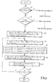
- Figure 3 shows an example of the processing flow of the servo processor. Whether or not a track jump command is received from the host processor is checked in step 30, and if not received, track following operation is performed.
- control goes to step 31 and either the FESoff(k) + a, FESoff(k) - a, or FESoff(k) value is received from the host processor.
- FESoff(k) + a is received in the first jump of the consecutive three track jumps
- FESoff(k) - a is received in the second jump
- FESoff(k) is received in the last jump. Therefore, the target value of the focus error signal in the first track jump is the value in which a positive offset is added to the original target value (normally, zero), and that in the second track jump is the value in which a negative offset is added to the original target value.
- the original target value is not modified.
- FESoff(k) is the FES offset value previously calculated with respect to the current track and stored in the memory.
- the initial value FESoff(0) is typically zero.
- step 32 the FES is read from an A/D convertor.
- the read value is denoted as FESad(k) in the following description.
- step 33 the offset value received in step 31 is subtracted from FESad(k). The value of the FES after the offset value subtracted is written as FESloop(k) in the following description.
- control enters a loop which is composed of the following steps after the maximum and minimum values of TESlpf have been cleared.
- TES is read from the A/D converter.
- the read value is denoted as TESad(k) in the following description (step 35).
- TESad(k) is passed through a low pass filter (step 36). Since the TES becomes like a sine wave at a track jump, the frequency is passed through, and the cut-off frequency of the low pass filter is set so that the frequency noise which is higher than that is eliminated.
- the value of the TES which passes the low pass filter is written as TESlpf.
- a drive signal for the focus actuator is generated in accordance with FESloop(k) and supplied to the focus actuator.
- a drive signal for the tracking actuator is generated in accordance with TESad(k) and supplied to the tracking actuator (step 37).
- step 37 TESlpf which is obtained in step 36 is compared with the maximum value obtained so far. If TESlpf is greater than the maximum value, the maximum value is updated with the value of TESlpf, and if TESlpf is not greater than the maximum value, nothing is done. Furthermore, TESlpf is also compared with the minimum value obtained so far. If TESlpf is smaller than the minimum value, the minimum value is updated with the value of TESlpf, and if TESlpf is not smaller than the minimum value, nothing is done.
- the loop keeps running until the jump ends (step 39).
- a jump is considered to be the completed with the generation of one sine wave cycle (TES).
- control goes to step 40.
- the maximum and minimum values of TESlpf are sent to the host processor (step 40). After that, normal track following operation is carried out.
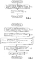
- FIG. 4 shows an example of the processing flow of the host processor. First, whether or not the drive is in track following mode is checked (step 41). If the drive is in track following mode, control goes to step 42. If the drive is in mode other than the track following mode, such as the loading or unloading of a disk, the sequence of the detection mode is cleared.
- step 42 If not at the timing of track jump in step 42, the current track address is read from a signal in which the pre-pit of the optical disk is reproduced. If at the timing of track jump, control proceeds to step 43.
- the FES offset value which has been written in advance is read from a memory location corresponding to the current track address. After that, a track jump command is sent to the servo processor, the FES offset value is transferred in accordance with the detection mode, and the detection of maximum and minimum values of TES is requested (steps 44 and 45).
- the detected maximum and minimum values of TESlpf are sent from the servo processor to the host: processor (step 46).
- the "processing corresponding to detection mode" in step 47 means the following three processings by the host processor.
- FIG. 5 shows an example of the flow of the processing with the detection mode being zero (0).
- the amplitude error TESamp+ of TES is calculated from the maximum and minimum values of TESlpf, which are detected in the first track jump, and written into the memory.
- the equation to calculate the amplitude error of TES which is common to step 51 and steps 61 and 71 to be described later is as follows.
- TESamp (TESlpf, max - TESlpf, min)/TES0
- TES0 is a target amplitude value of TES.
- step 52 the detection mode is set at 1 and the processing with detection mode being zero (0) ends.
- FIG. 6 shows an example of the flow of the processing with detection mode being 1.
- the amplitude error TESamp- of TES is calculated from the maximum and minimum values of TESlpf which are detected by the second track jump.
- TESamp+ which is calculated when the detection mode is zero (0), is read from the memory.
- step 63 the amplitude of TES is maximized in accordance with equation (1) shown in the figure, that is, an estimate FESnew of an offset which gives the optimum focus state is calculated.
- a new offset value FES(k+1) which is best suitable for later use in the focus servo control is calculated by combining FESoff(k) with FESnew in accordance with equation (2) shown in Figure 6. Coefficient C will be discussed later.
- step 64 FESoff(k+1) is written into a memory location corresponding to the current track address.
- step 65 the detection mode is set at 2 and the processing with detection mode being 1 ends.
- FIG. 7 shows an example of the flow of the processing with the detection mode being 2.
- step 71 the amplitude error TESamp and offset TESoff of TES are calculated from the maximum and minimum values of TESlpf.
- TESoff is calculated in accordance with the following equation.
- TESoff TESlpf, max + TESlpf, min
- step 72 the amplitude error TESamp(k) and offset TESoff(k) of TES are read from a memory location corresponding to the current track address. Their initial values TESamp(O) and TESoff(O) are typically zeroes.
- step 73 a new amplitude error value TESamp(k+1) and a new offset value TESoff(k+1) which are best suitable for later use in the tracking servo control are calculated respectively in accordance with equations (3) and (4) shown in Figure 7.
- the calculation results are written into a memory location corresponding to the current track address.
- the detection mode is set at zero (0) and the processing with the detection mode being 2 ends.
- the coefficient C used in update calculations of offset value and amplitude error value is above zero (0) and below (1). The closer the value is to zero, the quicker the response obtained. But, conversely, erroneous detection due to defects on a disk, etc., is highly likely. Therefore, the coefficient C must be selected in accordance with the actual fluctuating speeds of amplitudes and offsets.
- TESamp(k), TESoff(k), and FESoff(k) it is not necessary to store them in the memory by changing the location for each track.
- the typical data of several nearby tracks can be stored in a memory location which is determined by the upper bits of their track addresses.
- TESloop (TESad - TESoff(k+1)) * TESamp(k+1)
- FESloop FEsad - FESoff(k+1)
- the range of application of the invention will be readily extended beyond the embodiment described above.
- the number of track jumps performed respectively with the FES offset values being FESoff(k) + a, FESoff(k) - a, or FESoff(k) might be increased two times or more in order to increase the measurement accuracy of FESoff(k+1), TESoff(k+1), and TESamp(k+1).
- FESoff(k+1), TESoff(k+1), and TESamp(k+1) can be obtained accurately at one track jump, respectively, because the waveform of the tracking error signal generated at a track jump in track following mode is stable, unlike that in the seek mode.
- the sequence of the FES offset values to be transferred to the servo processor can be FESoff(k) + 2a, FESoff(k) + a, FESoff(k) - a, FESoff(k) - 2a, FESoff(k) in that order.
- the accuracy of the estimate of the FES offset can be increased if FESnew is obtained by averaging the value of equation (1) obtained from the TES amplitude when the FES offset values are FESoff(k) + 2a and FESoff(k) - 2a and the value of equation (1) obtained from the FES amplitude when the FES offset values are FESoff(k) + a and FESoff(k) - a.
- FIG 8 shows another example of the flow of the processing of the servo processor. Steps 80, 81, and 82 are added in comparison with those in Figure 3.
- the tracking actuator is not driven for that time. In this way, the response of the focus error signal can be made faster so as not to be delayed for track jump by driving the focus actuator in advance.
Landscapes
- Engineering & Computer Science (AREA)
- Signal Processing (AREA)
- Moving Of The Head For Recording And Reproducing By Optical Means (AREA)
- Optical Recording Or Reproduction (AREA)
- Moving Of The Head To Find And Align With The Track (AREA)
Applications Claiming Priority (3)
| Application Number | Priority Date | Filing Date | Title |
|---|---|---|---|
| JP5097519A JP2826252B2 (ja) | 1993-04-23 | 1993-04-23 | 光ディスク・ドライブ及びその信号校正方法 |
| JP97519/93 | 1993-04-23 | ||
| JP9751993 | 1993-04-23 |
Publications (2)
| Publication Number | Publication Date |
|---|---|
| EP0621586A1 true EP0621586A1 (fr) | 1994-10-26 |
| EP0621586B1 EP0621586B1 (fr) | 1999-10-06 |
Family
ID=14194512
Family Applications (1)
| Application Number | Title | Priority Date | Filing Date |
|---|---|---|---|
| EP94302548A Expired - Lifetime EP0621586B1 (fr) | 1993-04-23 | 1994-04-11 | Unité de disque optique |
Country Status (5)
| Country | Link |
|---|---|
| US (1) | US5504726A (fr) |
| EP (1) | EP0621586B1 (fr) |
| JP (1) | JP2826252B2 (fr) |
| KR (1) | KR950030104A (fr) |
| DE (1) | DE69420998T2 (fr) |
Families Citing this family (26)
| Publication number | Priority date | Publication date | Assignee | Title |
|---|---|---|---|---|
| US5777961A (en) * | 1994-06-27 | 1998-07-07 | Nec Corporation | Astigmatic difference correcting method for optical head and apparatus therefor |
| JP3465413B2 (ja) * | 1995-06-16 | 2003-11-10 | ソニー株式会社 | 光ディスク駆動装置およびフォーカス制御方法 |
| JP3846925B2 (ja) * | 1995-12-22 | 2006-11-15 | パイオニア株式会社 | トラッキングエラー信号の波形制御装置 |
| US6233210B1 (en) | 1998-10-09 | 2001-05-15 | Lsi Logic Corporation | Optical drive error tracking method and apparatus |
| US6633520B1 (en) * | 1999-06-14 | 2003-10-14 | Oak Technology, Inc. | Method and apparatus for searching in a disk drive |
| US7196979B2 (en) * | 2001-01-25 | 2007-03-27 | Dphi Acquisitions, Inc. | Calibration storage methods for a digital focus and tracking servo system with calibration |
| US7522480B2 (en) | 2001-01-25 | 2009-04-21 | Dphi Acquisitions, Inc. | Digital tracking servo system with multi-track seek with an acceleration clamp |
| KR100493026B1 (ko) * | 2002-09-09 | 2005-06-07 | 삼성전자주식회사 | 전화선 모뎀을 위한 강건한 심벌 타이밍 복구 회로 |
| ATE395693T1 (de) * | 2003-05-16 | 2008-05-15 | Thomson Licensing | Verfahren und gerät zur einstellung einer verstärkung zur erzeugung eines focusfehlersignals |
| JP4323873B2 (ja) * | 2003-06-13 | 2009-09-02 | 富士通株式会社 | 入出力インタフェース回路 |
| US7296142B2 (en) * | 2003-06-24 | 2007-11-13 | Seagate Technology Llc | Multi-tiered retry scheme for reading copies of information from a storage medium |
| KR100990101B1 (ko) * | 2003-10-16 | 2010-10-29 | 주식회사 히타치엘지 데이터 스토리지 코리아 | 포커스 에러신호의 노이즈 제거장치 및 방법 |
| TWI296799B (en) * | 2003-11-17 | 2008-05-11 | Tian Holdings Llc | Focusing controllter and the method thereof for an optical disk drive |
| TWI261226B (en) * | 2004-01-20 | 2006-09-01 | Via Tech Inc | Apparatus and method of dynamic adjusting the detection window |
| ATE418781T1 (de) * | 2004-07-14 | 2009-01-15 | Koninkl Philips Electronics Nv | Verbessertes kalibrierverfahren für spurfolgefehlersignale und plattenlaufwerk mit derartigem implementiertem verfahren |
| JP2008507071A (ja) * | 2004-07-14 | 2008-03-06 | コーニンクレッカ フィリップス エレクトロニクス エヌ ヴィ | 改善されたトラッキングエラー信号の較正方法、及びかかる方法を実現するディスクドライブ |
| CN1320536C (zh) * | 2004-08-03 | 2007-06-06 | 建兴电子科技股份有限公司 | 决定循轨误差信号补偿值的方法 |
| TWI261240B (en) | 2004-08-17 | 2006-09-01 | Via Tech Inc | Method for determining data storage quality of optical disc |
| JP2007080466A (ja) * | 2005-09-16 | 2007-03-29 | Toshiba Corp | 光ヘッド装置及び光ディスク装置 |
| JP2007102864A (ja) * | 2005-09-30 | 2007-04-19 | Toshiba Samsung Storage Technology Corp | 光ディスク装置および光ディスク装置のフォーカス制御方法 |
| EP2050096B1 (fr) * | 2006-08-04 | 2010-11-24 | Koninklijke Philips Electronics N.V. | Routine d'optimisation de foyer améliorée avec réglages de sauts sous-optimaux dans des systèmes à disques optiques |
| US8811132B2 (en) * | 2006-10-24 | 2014-08-19 | Mediatek Inc. | Method for calibrating a tracking error signal of an optical disk drive |
| US7839732B2 (en) * | 2007-04-14 | 2010-11-23 | Mediatek Inc. | System and method for calibrating recording track offset of optical storage device |
| US7778120B2 (en) * | 2007-05-08 | 2010-08-17 | Mediatek Inc. | Calibration method for determining servo parameters for accessing an optical disc |
| US8199620B2 (en) * | 2008-08-14 | 2012-06-12 | Mediatek Inc. | Method for performing servo defect compensating operation by compensating servo-related signal derived from reading optical medium and related optical disc drive system with DSP |
| TWI419156B (zh) * | 2009-01-09 | 2013-12-11 | Quanta Storage Inc | 聚焦誤差訊號對稱校正方法 |
Citations (6)
| Publication number | Priority date | Publication date | Assignee | Title |
|---|---|---|---|---|
| JPS58158045A (ja) * | 1982-03-16 | 1983-09-20 | Nec Corp | 焦点制御修正装置 |
| JPH0449533A (ja) * | 1990-06-18 | 1992-02-18 | Ricoh Co Ltd | フオーカスオフセット補正方法 |
| EP0478367A2 (fr) * | 1990-09-28 | 1992-04-01 | International Business Machines Corporation | Commande du système de focalisation du faisceau de lumière dans un appareil optique de stockage de données |
| EP0478314A2 (fr) * | 1990-09-28 | 1992-04-01 | International Business Machines Corporation | Tourne-disque optique avec calibration du signal d'erreur de focalisation |
| US5485544A (en) | 1989-02-17 | 1996-01-16 | Hitachi, Ltd. | History sensitive help control method and system |
| EP0890900A2 (fr) | 1997-07-07 | 1999-01-13 | Informix Software, Inc. | Procédé et système de traitement de données |
Family Cites Families (7)
| Publication number | Priority date | Publication date | Assignee | Title |
|---|---|---|---|---|
| CA1261467A (fr) * | 1985-11-28 | 1989-09-26 | Akira Minami | Dispositif de commande de servomecanisme de focalisation pour lecteur de disques optiques a reglage du decalage |
| JPH02285526A (ja) * | 1989-04-27 | 1990-11-22 | Olympus Optical Co Ltd | トラッキングサーボループのオフセット補正装置 |
| US5097458A (en) * | 1989-05-29 | 1992-03-17 | Ricoh Company, Ltd. | Servo control system for optical disk device |
| US5351224A (en) * | 1990-03-08 | 1994-09-27 | Oki Electric Industry Co., Ltd. | Adjustment of tracking servo and focusing servo in optical data recording/reproducing apparatus |
| JPH04265532A (ja) * | 1991-02-19 | 1992-09-21 | Oki Electric Ind Co Ltd | 光学的情報記録再生装置 |
| JPH04278233A (ja) * | 1991-03-07 | 1992-10-02 | Matsushita Electric Ind Co Ltd | 光ディスク装置 |
| US5343454A (en) * | 1991-11-22 | 1994-08-30 | Matsushita Electric Industrial Co., Ltd. | Tracking control apparatus for correcting tracking error signal according to approximate equation of a function of track address |
-
1993
- 1993-04-23 JP JP5097519A patent/JP2826252B2/ja not_active Expired - Fee Related
-
1994
- 1994-04-06 US US08/223,564 patent/US5504726A/en not_active Expired - Fee Related
- 1994-04-11 EP EP94302548A patent/EP0621586B1/fr not_active Expired - Lifetime
- 1994-04-11 DE DE69420998T patent/DE69420998T2/de not_active Expired - Fee Related
- 1994-04-14 KR KR1019940007808A patent/KR950030104A/ko not_active Ceased
Patent Citations (7)
| Publication number | Priority date | Publication date | Assignee | Title |
|---|---|---|---|---|
| JPS58158045A (ja) * | 1982-03-16 | 1983-09-20 | Nec Corp | 焦点制御修正装置 |
| US5485544A (en) | 1989-02-17 | 1996-01-16 | Hitachi, Ltd. | History sensitive help control method and system |
| JPH0449533A (ja) * | 1990-06-18 | 1992-02-18 | Ricoh Co Ltd | フオーカスオフセット補正方法 |
| US5218588A (en) * | 1990-06-18 | 1993-06-08 | Ricoh Company, Ltd. | Focus offset correction method |
| EP0478367A2 (fr) * | 1990-09-28 | 1992-04-01 | International Business Machines Corporation | Commande du système de focalisation du faisceau de lumière dans un appareil optique de stockage de données |
| EP0478314A2 (fr) * | 1990-09-28 | 1992-04-01 | International Business Machines Corporation | Tourne-disque optique avec calibration du signal d'erreur de focalisation |
| EP0890900A2 (fr) | 1997-07-07 | 1999-01-13 | Informix Software, Inc. | Procédé et système de traitement de données |
Non-Patent Citations (2)
| Title |
|---|
| PATENT ABSTRACTS OF JAPAN vol. 16, no. 231 (P - 1361) 28 May 1992 (1992-05-28) * |
| PATENT ABSTRACTS OF JAPAN vol. 7, no. 282 (P - 243) 16 December 1983 (1983-12-16) * |
Also Published As
| Publication number | Publication date |
|---|---|
| EP0621586B1 (fr) | 1999-10-06 |
| JPH06309681A (ja) | 1994-11-04 |
| DE69420998D1 (de) | 1999-11-11 |
| US5504726A (en) | 1996-04-02 |
| DE69420998T2 (de) | 2000-04-20 |
| KR950030104A (ko) | 1995-11-24 |
| JP2826252B2 (ja) | 1998-11-18 |
Similar Documents
| Publication | Publication Date | Title |
|---|---|---|
| EP0621586B1 (fr) | Unité de disque optique | |
| US5502698A (en) | Automatic attitude correcting system for optical disc device | |
| EP0392561B1 (fr) | Unité de disque optique | |
| US5164932A (en) | Acquiring a best focus using a focus signal offset | |
| US7054241B2 (en) | Optical disc apparatus | |
| KR100646189B1 (ko) | 광정보 기록방법 및 장치 그리고 광정보 기록 제어프로그램을 기록한 기록매체 | |
| US7327643B2 (en) | Radial tilt compensating optical disk apparatus using tracking control loop gain | |
| EP1394785B1 (fr) | Méthode et appareil de correction de l' inclinaison d' un rayon lumineux dirigé vers un support d' enregistrement optique | |
| EP1385156B1 (fr) | Méthode et appareil pour corriger l'abérration sphérique | |
| US6498772B1 (en) | Optical disc apparatus | |
| WO2002073609A1 (fr) | Dipspositif et procede de controle d'inclinaison | |
| EP1376550A2 (fr) | Dispositif de correction de dévers | |
| EP1477970A1 (fr) | Lecteur de disque | |
| JP2000215454A (ja) | 光ディスク記録装置、及び光ディスクへの情報記録方法 | |
| US20030016599A1 (en) | Optical disc apparatus | |
| JP3033066B2 (ja) | フォーカス位置の調整装置 | |
| US7298679B2 (en) | Write power determining method and write power control method for optical disk drive | |
| EP1938318B1 (fr) | Dispositif et procede de balayage d'un support d'enregistrement optique et support d'enregistrement optique | |
| JPH06195718A (ja) | 光学的情報記録再生装置 | |
| US7260042B2 (en) | Generating tracking control output signals for compensating tracking error signals | |
| JPH02294940A (ja) | 光学式情報記録再生装置 | |
| KR20070064655A (ko) | 틸트 교정기를 갖는 광 디스크 장치와, 틸트 교정기를 갖는광 디스크 장치를 이용하여 광 디스크를 판독 및/또는기록하는 방법 | |
| JPH08273182A (ja) | 回転式記録装置 | |
| JPH0793785A (ja) | 光ディスク装置の自動補正装置 | |
| JPH1055543A (ja) | 光情報再生装置 |
Legal Events
| Date | Code | Title | Description |
|---|---|---|---|
| PUAI | Public reference made under article 153(3) epc to a published international application that has entered the european phase |
Free format text: ORIGINAL CODE: 0009012 |
|
| AK | Designated contracting states |
Kind code of ref document: A1 Designated state(s): DE FR GB |
|
| 17P | Request for examination filed |
Effective date: 19950227 |
|
| 17Q | First examination report despatched |
Effective date: 19980520 |
|
| GRAG | Despatch of communication of intention to grant |
Free format text: ORIGINAL CODE: EPIDOS AGRA |
|
| GRAG | Despatch of communication of intention to grant |
Free format text: ORIGINAL CODE: EPIDOS AGRA |
|
| GRAH | Despatch of communication of intention to grant a patent |
Free format text: ORIGINAL CODE: EPIDOS IGRA |
|
| GRAH | Despatch of communication of intention to grant a patent |
Free format text: ORIGINAL CODE: EPIDOS IGRA |
|
| GRAA | (expected) grant |
Free format text: ORIGINAL CODE: 0009210 |
|
| AK | Designated contracting states |
Kind code of ref document: B1 Designated state(s): DE FR GB |
|
| REF | Corresponds to: |
Ref document number: 69420998 Country of ref document: DE Date of ref document: 19991111 |
|
| ET | Fr: translation filed | ||
| PLBE | No opposition filed within time limit |
Free format text: ORIGINAL CODE: 0009261 |
|
| STAA | Information on the status of an ep patent application or granted ep patent |
Free format text: STATUS: NO OPPOSITION FILED WITHIN TIME LIMIT |
|
| 26N | No opposition filed | ||
| PGFP | Annual fee paid to national office [announced via postgrant information from national office to epo] |
Ref country code: FR Payment date: 20010417 Year of fee payment: 8 |
|
| PGFP | Annual fee paid to national office [announced via postgrant information from national office to epo] |
Ref country code: DE Payment date: 20010426 Year of fee payment: 8 |
|
| REG | Reference to a national code |
Ref country code: GB Ref legal event code: IF02 |
|
| PGFP | Annual fee paid to national office [announced via postgrant information from national office to epo] |
Ref country code: GB Payment date: 20020403 Year of fee payment: 9 |
|
| PG25 | Lapsed in a contracting state [announced via postgrant information from national office to epo] |
Ref country code: DE Free format text: LAPSE BECAUSE OF NON-PAYMENT OF DUE FEES Effective date: 20021101 |
|
| PG25 | Lapsed in a contracting state [announced via postgrant information from national office to epo] |
Ref country code: FR Free format text: LAPSE BECAUSE OF NON-PAYMENT OF DUE FEES Effective date: 20021231 |
|
| REG | Reference to a national code |
Ref country code: FR Ref legal event code: ST |
|
| PG25 | Lapsed in a contracting state [announced via postgrant information from national office to epo] |
Ref country code: GB Free format text: LAPSE BECAUSE OF NON-PAYMENT OF DUE FEES Effective date: 20030411 |
|
| GBPC | Gb: european patent ceased through non-payment of renewal fee |
Effective date: 20030411 |