EP0621659A1 - Hystérésis dans un circuit de détection de présence de fiche - Google Patents
Hystérésis dans un circuit de détection de présence de fiche Download PDFInfo
- Publication number
- EP0621659A1 EP0621659A1 EP94105432A EP94105432A EP0621659A1 EP 0621659 A1 EP0621659 A1 EP 0621659A1 EP 94105432 A EP94105432 A EP 94105432A EP 94105432 A EP94105432 A EP 94105432A EP 0621659 A1 EP0621659 A1 EP 0621659A1
- Authority
- EP
- European Patent Office
- Prior art keywords
- plug
- receptacle
- relay
- power
- sensor
- Prior art date
- Legal status (The legal status is an assumption and is not a legal conclusion. Google has not performed a legal analysis and makes no representation as to the accuracy of the status listed.)
- Granted
Links
Images

Classifications
-
- H—ELECTRICITY
- H02—GENERATION; CONVERSION OR DISTRIBUTION OF ELECTRIC POWER
- H02J—ELECTRIC POWER NETWORKS; CIRCUIT ARRANGEMENTS OR SYSTEMS FOR SUPPLYING OR DISTRIBUTING ELECTRIC POWER; SYSTEMS FOR STORING ELECTRIC ENERGY
- H02J3/00—Circuit arrangements for AC mains or AC distribution networks
-
- H—ELECTRICITY
- H01—ELECTRIC ELEMENTS
- H01H—ELECTRIC SWITCHES; RELAYS; SELECTORS; EMERGENCY PROTECTIVE DEVICES
- H01H47/00—Circuit arrangements not adapted to a particular application of the relay and designed to obtain desired operating characteristics or to provide energising current
- H01H47/22—Circuit arrangements not adapted to a particular application of the relay and designed to obtain desired operating characteristics or to provide energising current for supplying energising current for relay coil
- H01H47/24—Circuit arrangements not adapted to a particular application of the relay and designed to obtain desired operating characteristics or to provide energising current for supplying energising current for relay coil having light-sensitive input
-
- H—ELECTRICITY
- H01—ELECTRIC ELEMENTS
- H01R—ELECTRICALLY-CONDUCTIVE CONNECTIONS; STRUCTURAL ASSOCIATIONS OF A PLURALITY OF MUTUALLY-INSULATED ELECTRICAL CONNECTING ELEMENTS; COUPLING DEVICES; CURRENT COLLECTORS
- H01R13/00—Details of coupling devices of the kinds covered by groups H01R12/70 or H01R24/00 - H01R33/00
- H01R13/64—Means for preventing incorrect coupling
- H01R13/641—Means for preventing incorrect coupling by indicating incorrect coupling; by indicating correct or full engagement
-
- H—ELECTRICITY
- H01—ELECTRIC ELEMENTS
- H01R—ELECTRICALLY-CONDUCTIVE CONNECTIONS; STRUCTURAL ASSOCIATIONS OF A PLURALITY OF MUTUALLY-INSULATED ELECTRICAL CONNECTING ELEMENTS; COUPLING DEVICES; CURRENT COLLECTORS
- H01R13/00—Details of coupling devices of the kinds covered by groups H01R12/70 or H01R24/00 - H01R33/00
- H01R13/66—Structural association with built-in electrical component
- H01R13/70—Structural association with built-in electrical component with built-in switch
- H01R13/703—Structural association with built-in electrical component with built-in switch operated by engagement or disengagement of coupling parts, e.g. dual-continuity coupling part
- H01R13/7036—Structural association with built-in electrical component with built-in switch operated by engagement or disengagement of coupling parts, e.g. dual-continuity coupling part the switch being in series with coupling part, e.g. dead coupling, explosion proof coupling
- H01R13/7038—Structural association with built-in electrical component with built-in switch operated by engagement or disengagement of coupling parts, e.g. dual-continuity coupling part the switch being in series with coupling part, e.g. dead coupling, explosion proof coupling making use of a remote controlled switch, e.g. relais, solid state switch activated by the engagement of the coupling parts
Definitions
- This invention relates to a control for an automatic power receptacle and, more particularly, to use of hysteresis in such a control.
- one or more branch circuits are wired to distribute electrical power to load devices, such as outlet receptacles or light fixtures.
- load devices such as outlet receptacles or light fixtures.
- the receptacle or fixture is hardwired directly to the branch circuit, with power to the device being turned on or off at the device itself.
- a light fixture might include a pull cord for actuating a switch, while a small appliance might include a power switch.
- a system controller directs all communication functions into a system controller. This gives a home owner flexible communication and power control from anywhere in the home there is a control panel or switch, or even anywhere there is a telephone, such as the car or office.
- An intelligent outlet receptacle allows individual appliances to be separately and automatically controlled as necessary or desired. To do so, some means must be provided for controlling switching of power to an electrical outlet receptacle. A practical switching device must be inexpensive and reliable.
- a latching relay has been found to be readily adaptable to such an application. A latching relay is latched when connected to a positive polarity voltage source and unlatched when connected to a negative polarity voltage source.
- Some applications require that electrical power be applied to an outlet receptacle only when in use.
- the outlet receptacle is disconnected from the power source when no plug is present and disconnected to the power source when a plug is inserted in the receptacle.
- such a control circuit enables a particular outlet receptacle to be controlled both in response to presence or absence of a plug and demands of external user or automatic control functions.
- An automatic control such as described requires that insertion of a plug be detected and an electronic signal be delivered to a control to indicate presence or absence of the plug. While inserting or removing the plug, it is possible that the sensing system could cycle, resulting in relay "chatter”. Obviously, it is desirable to prevent relay chatter.
- the present invention is directed to solving one or more of the problems discussed above in a novel and simple manner.
- an automatic power receptacle including a hysteresis control.
- an automatically switched power receptacle including an outlet receptacle adapted to receive a plug.
- a relay is connected between the outlet receptacle and a source of power to selectively power the receptacle.
- a plug presence sensor in proximity to the receptacle senses presence of a plug in the receptacle.
- An automatic control circuit is connected between the relay and the plug presence sensor for selectively energizing said relay to power the receptacle incident to the sensor sensing presence of a plug, the control circuit including a hysteresis circuit to prevent cycling of the relay.
- the relay comprises a latching relay.
- the plug presence sensor comprises a light source and a light sensor, the light source and light sensor being disposed on opposite sides of a path of movement of a plug being inserted in the receptacle.
- the hysteresis circuit comprises means for dimming the light source when the relay is energized.
- the light source comprises an LED and the light sensor comprises a photo-sensitive switching device.
- an automatic switched power receptacle including an outlet receptacle adapted to receive a plug.
- a relay is connected between the power receptacle and a source of power to selectively power the receptacle.
- a plug presence sensor in proximity to the receptacle senses presence of a plug in the receptacle.
- the plug presence sensor comprises a light source and light sensor, the light source and light sensor being disposed on opposite sides of a path of movement of a plug being inserted in the receptacle.
- An automatic control circuit is connected between the relay and the plug presence sensor for selectively energizing the relay to power the receptacle incident to the sensor sensing presence of a plug.
- an automatically switched power receptacle including an outlet receptacle adapted to receive a plug.
- a relay is connected between the outlet receptacle and a source of power to selectively power the receptacle.
- a plug presence sensor in proximity to the receptacle senses presence of a plug in the receptacle.
- the plug presence sensor comprises a light source and a light sensor. The light source and light sensor are disposed on opposite sides of a path of movement of a plug being inserted in the receptacle. The light sensor assumes a first or second state incident to the sensed light being above or below a select level.
- An automatic control circuit is connected between the relay and the plug presence sensor for selectively energizing the relay to power the receptacle incident to the light sensor being in the second state.
- the control circuit includes means for determining if the relay is energized and controlling the light source to dim the light source if the relay is energized.
- the determining means dims the light source incident to the light sensor being in the second state.
- the plug presence sensor comprises an LED and light sensor in the form of a photo-transistor which senses presence of a plug in a receptacle.
- the sensor is monitored by a microprocessor to control latching of a relay.
- the relay is de-energized, so that no power is present at the receptacle, when no plug is inserted.
- the relay is energized to provide power.
- an input to the microcontroller indicates the status of the light sensor, i.e., the presence or absence of the plug.
- the prong of the plug when present, cuts off light from the LED. Hysteresis is provided by enhancing the feedback signal.
- the relay is energized. This turns on a relay drive output which also is connected to the LED to dim the LED. Conversely, when the plug is removed, additional light is sensed until a point is reached at which the plug is considered to have been sufficiently removed to turn the relay off. At this time, the relay drive output is set low to brighten the output from the LED's so that the sensed light increases.
- Fig. 1 illustrates an automatically switched power receptacle 10 in accordance with the invention.
- the switched power receptacle 10 includes a first outlet receptacle 12 and a second outlet receptacle 14, each in a housing 16.
- Each outlet receptacle 12 and 14 is adapted to receive a conventional three-prong plug for selectively providing electrical power thereto.
- the illustrated power receptacles 12 and 14 includes additional receptacle structure for data communication which are not relevant to the claimed invention and therefore are not described in detail herein.
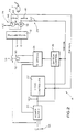
- Fig. 2 illustrates a control circuit 18 for the power receptacle 10 in block diagram form.
- the control circuit 18 includes a power supply circuit 20, a logic controller 22, an H-bridge switching circuit 24, a switch control circuit 26, a plug presence sensor 28 and a hysteresis circuit 29.
- the control circuit 18 is shown in association with the first outlet receptacle 12. A similar circuit would be used for the second outlet receptacle 14. Both such control circuits could use a common logic controller 22 and power supply 20.
- a latching relay 30 controls the first outlet receptacle 12.
- the latching relay 30 has a relay coil 32 and an electrical contact 34 switched by the relay coil 32.
- the relay coil 32 is latched when connected to a positive polarity voltage source and unlatched when connected to a negative polarity voltage source.
- Such a latching relay 30 is permanently magnetized so that upon actuation by relatively high current of positive polarity, an included plunger is magnetically retained in an actuated position to close the contact 34.
- the reverse polarity power is connected to the relay coil 32, then the magnetic field is reduced so that a spring force returns the plunger to an unlatched position opening the contact 34.
- the latching relay 30 may be of any conventional construction.
- the circuit does not require that the relay 30 be a latching relay. Instead, a conventional non-latching type relay could also be used, as will be obvious to those skilled in the art.
- the power supply 20 is connected to a source of power 35 represented by input lines labeled "H" for hot, “N” for neutral and “G” for ground.
- the electrical contact 34 is connected between the hot terminal "H” and the hot terminal of the outlet receptacle 12 for selectively applying power to the same.
- the neutral and ground terminals are directly connected to the corresponding terminals of the outlet receptacle 12.
- the power supply circuit 20 develops regulated DC power for operating the logic controller 22, the H-bridge circuit 24 and the switch control circuit 26.
- the logic controller 22 may be an integrated circuit including hardwired gates and latches to perform the described functions, or may be a conventional microcontroller programmed for developing logic signals as necessary for the particular application.
- the logic controller 22 communicates with the switch control circuit 26, the plug presence sensor circuit 28, and the hysteresis circuit 29 via a switch control line labeled "SWCON" and a power enable feedback line labeled "PRWEN".
- the H-bridge switch circuit 24 comprises an H-bridge circuit of conventional construction which controls polarity of power applied to the relay coil 32.
- the relay coil 32 being of the remnant latching type, requires a well-defined pulse to operate.
- the pulsing of the H-bridge circuit 24 is controlled by the switch control circuit 26. Particularly, when the switch control line SWCON goes high, a first pulse is developed to control the H-bridge circuit to connect the relay coil 32 with positive polarity power. When the switch control line SWCON goes low, a second pulse is developed to control the H-bridge circuit 24 to provide negative polarity power to the relay coil 32.
- a current limit is included in the H-bridge circuit 24 to avoid over-magnetization during unlatching.
- the plug presence sensor 28 comprises an LED 36 and a photo-transistor 38.
- the LED 36 is connected between a supply node, labeled VCC, and a resistor 40 to ground.
- the collector of the photo-transistor 38 is connected to supply, while its emitter is connected via a resistor 44 to ground.
- the junction between the resistor 44 and the emitter of the photo-transistor 38 is connected as feedback to the power enable line PWREN.
- a photo-sensitive switching device such as a photo-diode, and appropriate amplifying circuitry could be used, as would be apparent to those skilled in the art.
- the hysteresis circuit 29 comprises an additional resistor 42 connected between the junction of the LED 36 and the resistor 40 to the switch control line SWCON.
- the LED 36 and the photo-transistor 38 are positioned in the housing 16 to be on opposite sides of a path of movement of one of the prongs of a plug P being inserted in the outlet receptacle 12.
- the LED 36 acts as a light source directing light, as indicated by the arrow 46, to drive the photo-transistor 38.
- the prongs of the plug P break the beam of light to gradually decrease the amount of light sensed by the photo-transistor 38. Decreasing the amount of light turns the transistor 38 off.
- the status of the photo-transistor 38 is fed back to the logic controller 22 on the power enable line PWREN.
- the plug presence sensor 28 could alternatively sense reflection of light. In such an application the presence of the plug blade would reflect light to be sensed by the photo-transistor. Thus, actuation would be by a presence of light, rather than an absence of light.
- a flow diagram illustrates a program implemented in the logic controller 22 for controlling operation of the control circuit 18.
- the logic controller 22 may include a program for performing many different functions, such as providing remote control of the latching relay 30.
- the flow diagram illustrated in Fig. 3 is a portion of such program related specifically to the automatic control for the outlet receptacle 12 in response to presence of a plug.
- the control starts at a node 50 and then a decision block 52 determines if there is a change in the power enable line PWREN to the logic controller. If not, then the routine ends.
- a change occurs either when the plug P is inserted or is removed from the outlet receptacle 12 causing a change in state of the photo-transistor 38.
- the photo-transistor 38 is normally in an "on” state with no plug P present, as a result of light emitted sensed from the LED 36. When a plug P is inserted, the light is cut off to switch the photo-transistor 38 to the "off" state.
- a decision block 54 determines if the change represents a plug being in the socket, i.e., the power enable line going low. If so, then the switch control line SWCON is set high at a block 56 and the routine ends. If not, then the switch control line SWCON is set low at a block 58 and the routine ends.
- the switch control circuit 26 controls the H-bridge circuit 24 to generate a positive polarity pulse to the relay coil 32 to close the contact 34 to power the outlet receptacle. Conversely, when the switch control SWCON goes low, the transition is sensed by the switch control circuit 26, causing the H-bridge circuit 24 to generate a negative polarity pulse to the relay coil 32 to open the contact 34 and disable the outlet receptacle 12.
- the switch control line SWCON is also connected via the hysteresis circuit 29 to the LED 36. Particularly, when the switch control line SWCON transitions from a low state to a high state, it decreases current through the LED 36, causing it to dim. When the switch control line SWCON transitions from a high state to a low state, it increases current through the LED 36, causing it to brighten. This control of illumination from the LED 36 enhances the effect on the photo-transistor 38 resulting from insertion or removal of a plug P. This provides hysteresis to prevent cycling of the latching relay 30, which would otherwise result if the plug P was slowly inserted or removed, which could modulate the amount of light received by the photo-transistor 38.
- the amount of light sensed by the photo-transistor 38 gradually decreases.
- the latching relay 30 is latched. This is done by turning on the SWCON output, which dims the LED 36. The dimming of the LED further decreases light sensed by the photo-transistor 38 so if the plug P is slightly removed, the removal would not cause a reverse change of state of the photo-transistor 38.
- the circuit uses an electronic plug presence sensor with the hysteresis circuit varying intensity of the light to provide the hysteresis function.
- an electrical contact could be used as a plug presence sensor, with hysteresis being provided by incorporating a time delay.
- an electrical hysteresis circuit is provided which prevents cycling of the latching relay 30 in an automatic power receptacle circuit.
Landscapes
- Engineering & Computer Science (AREA)
- Power Engineering (AREA)
- Details Of Connecting Devices For Male And Female Coupling (AREA)
- Keying Circuit Devices (AREA)
Applications Claiming Priority (2)
| Application Number | Priority Date | Filing Date | Title |
|---|---|---|---|
| US49885 | 1993-04-20 | ||
| US08/049,885 US5621256A (en) | 1993-04-20 | 1993-04-20 | Hysteresis in a circuit for sensing presence of a plug |
Publications (2)
| Publication Number | Publication Date |
|---|---|
| EP0621659A1 true EP0621659A1 (fr) | 1994-10-26 |
| EP0621659B1 EP0621659B1 (fr) | 1997-08-27 |
Family
ID=21962255
Family Applications (1)
| Application Number | Title | Priority Date | Filing Date |
|---|---|---|---|
| EP94105432A Expired - Lifetime EP0621659B1 (fr) | 1993-04-20 | 1994-04-08 | Hystérésis dans un circuit de détection de présence de fiche |
Country Status (5)
| Country | Link |
|---|---|
| US (1) | US5621256A (fr) |
| EP (1) | EP0621659B1 (fr) |
| JP (1) | JP2602477B2 (fr) |
| KR (1) | KR0159797B1 (fr) |
| DE (1) | DE69405145T2 (fr) |
Cited By (7)
| Publication number | Priority date | Publication date | Assignee | Title |
|---|---|---|---|---|
| DE29610409U1 (de) * | 1996-06-13 | 1996-09-05 | Siemens AG, 80333 München | Elektrische Steckverbindung |
| WO2000041275A1 (fr) * | 1998-12-31 | 2000-07-13 | Power-Off Products Llc | Prise femelle de securite adaptative/reactive |
| GB2443904A (en) * | 2007-05-04 | 2008-05-21 | Tana Leonardus Wondergem | Remote-controlled electrical mains socket |
| WO2009068908A3 (fr) * | 2007-11-28 | 2009-08-06 | Balfour Beatty Plc | Dispositif de sécurité électrique |
| US7575467B2 (en) | 2006-12-27 | 2009-08-18 | Thomas Wilmer Ferguson | Electrically safe receptacle |
| ITBA20090017A1 (it) * | 2009-05-12 | 2010-11-13 | Adf Work & Service S R L | Prese meccatroniche per serie civile/industriale con relativi sistemi di commutazione di utenze elettriche tramite potenziale di terra. |
| EP3324498A1 (fr) * | 2016-11-16 | 2018-05-23 | Beijing Xiaomi Mobile Software Co., Ltd. | Procédé et appareil d'activation d'énergie pour bande d'alimentation, programme d'ordinateur et support d'enregistrement |
Families Citing this family (20)
| Publication number | Priority date | Publication date | Assignee | Title |
|---|---|---|---|---|
| DE19722922A1 (de) * | 1997-05-31 | 1998-12-03 | Lufthansa Technik Ag | Spannungsversorgungsvorrichtung |
| US6599141B2 (en) | 2001-04-27 | 2003-07-29 | General Dynamics Ots (Aerospace), Inc. | Apparatus for providing AC power to airborne in-seat power systems |
| KR100419224B1 (ko) * | 2002-01-19 | 2004-02-21 | 삼성전자주식회사 | 전원 절약 모드 기능을 갖는 전원 장치 |
| RU2241275C1 (ru) * | 2003-03-27 | 2004-11-27 | Общество с ограниченной ответственностью "Электронгарантсервис" | Первичный импульсный фотопреобразователь |
| JP4401758B2 (ja) * | 2003-12-18 | 2010-01-20 | アルプス電気株式会社 | 特定周波数成分減衰装置および電力線搬送通信システム |
| US20080055024A1 (en) * | 2006-08-31 | 2008-03-06 | Motorola, Inc. | System and method for protection of unplanned state changes of a magnetic latching relay |
| EP2577878A4 (fr) * | 2010-05-28 | 2016-12-07 | Ronen Apelker | Système et procédé de commande de charges automatisé |
| CA2774364C (fr) | 2011-04-18 | 2014-01-28 | Norman R. Byrne | Systeme electrique a circuit limiteur |
| TWM422823U (en) * | 2011-09-15 | 2012-02-11 | Delta Electronics Inc | Power distribution unit and power input module compatible therewith |
| EP2656805B1 (fr) * | 2012-04-26 | 2017-03-15 | Erbe Elektromedizin GmbH | Agencement de douille pour un appareil électromédical |
| US9155173B2 (en) * | 2012-10-01 | 2015-10-06 | Creston Electronics, Inc. | Dual-mode dimmable receptacle |
| WO2017205252A1 (fr) * | 2016-05-24 | 2017-11-30 | Hubbell Incorporated | Prise électrique |
| CA2981704C (fr) | 2016-10-07 | 2020-10-20 | Norman R. Byrne | Cordon d'alimentation electrique dote d'un interrupteur intelligent |
| US10734769B2 (en) | 2017-07-19 | 2020-08-04 | Western Technology, Inc. | Safety electrical power connector |
| US11271384B2 (en) | 2017-07-27 | 2022-03-08 | Western Technology, Inc. | Power supply interlock |
| FR3078171B1 (fr) * | 2018-02-22 | 2020-09-11 | Sagemcom Energy & Telecom Sas | Equipement electrique comportant une premiere partie et une deuxieme partie isolee electriquement de la premiere partie |
| CN109407560B (zh) * | 2018-10-24 | 2021-05-11 | 苏州金迪智能科技有限公司 | 一种计算机远程控制家电工作的装置 |
| US11424561B2 (en) | 2019-07-03 | 2022-08-23 | Norman R. Byrne | Outlet-level electrical energy management system |
| US12301045B2 (en) * | 2022-04-28 | 2025-05-13 | St Engineering Telematics Wireless Ltd. | Zero return photoelectric control system |
| US12431621B2 (en) | 2023-01-26 | 2025-09-30 | Honeywell International Inc. | Compact dual band antenna |
Citations (4)
| Publication number | Priority date | Publication date | Assignee | Title |
|---|---|---|---|---|
| EP0409226A2 (fr) * | 1989-07-21 | 1991-01-23 | Hitachi, Ltd. | Système de commande de source d'alimentation |
| US5222164A (en) * | 1992-08-27 | 1993-06-22 | International Business Machines Corporation | Electrically isolated optical connector identification system |
| EP0556754A2 (fr) * | 1992-02-18 | 1993-08-25 | Molex Incorporated | Prise de puissance commutée automatiquement |
| EP0581078A2 (fr) * | 1992-07-14 | 1994-02-02 | GEWISS S.p.A. | Distributeur électrique au moyen de la vérification d'état de charge, particulièrement pour utilisateurs civils et industriel |
Family Cites Families (3)
| Publication number | Priority date | Publication date | Assignee | Title |
|---|---|---|---|---|
| US4970623A (en) * | 1988-12-29 | 1990-11-13 | Hewlett-Packard Company | Peripheral device power activation circuit and method therefor |
| US5164609A (en) * | 1990-06-08 | 1992-11-17 | Donnelly Corporation | Controllable power distribution system |
| US5418679A (en) * | 1993-04-06 | 1995-05-23 | Molex Incorporated | Circuit for overriding the cripple mode so that the relay remains latched |
-
1993
- 1993-04-20 US US08/049,885 patent/US5621256A/en not_active Expired - Fee Related
-
1994
- 1994-04-08 EP EP94105432A patent/EP0621659B1/fr not_active Expired - Lifetime
- 1994-04-08 DE DE69405145T patent/DE69405145T2/de not_active Expired - Fee Related
- 1994-04-13 JP JP6100634A patent/JP2602477B2/ja not_active Expired - Lifetime
- 1994-04-19 KR KR1019940008174A patent/KR0159797B1/ko not_active Expired - Fee Related
Patent Citations (4)
| Publication number | Priority date | Publication date | Assignee | Title |
|---|---|---|---|---|
| EP0409226A2 (fr) * | 1989-07-21 | 1991-01-23 | Hitachi, Ltd. | Système de commande de source d'alimentation |
| EP0556754A2 (fr) * | 1992-02-18 | 1993-08-25 | Molex Incorporated | Prise de puissance commutée automatiquement |
| EP0581078A2 (fr) * | 1992-07-14 | 1994-02-02 | GEWISS S.p.A. | Distributeur électrique au moyen de la vérification d'état de charge, particulièrement pour utilisateurs civils et industriel |
| US5222164A (en) * | 1992-08-27 | 1993-06-22 | International Business Machines Corporation | Electrically isolated optical connector identification system |
Cited By (12)
| Publication number | Priority date | Publication date | Assignee | Title |
|---|---|---|---|---|
| DE29610409U1 (de) * | 1996-06-13 | 1996-09-05 | Siemens AG, 80333 München | Elektrische Steckverbindung |
| WO2000041275A1 (fr) * | 1998-12-31 | 2000-07-13 | Power-Off Products Llc | Prise femelle de securite adaptative/reactive |
| US6176718B1 (en) | 1998-12-31 | 2001-01-23 | Power-Off Products, Llc | Adaptive/reactive safety plug receptacle |
| US6428334B2 (en) | 1998-12-31 | 2002-08-06 | Power-Off Products, Llc | Adaptive/reactive safety plug receptacle |
| US7575467B2 (en) | 2006-12-27 | 2009-08-18 | Thomas Wilmer Ferguson | Electrically safe receptacle |
| GB2443904A (en) * | 2007-05-04 | 2008-05-21 | Tana Leonardus Wondergem | Remote-controlled electrical mains socket |
| GB2443904B (en) * | 2007-05-04 | 2009-03-25 | Tana Leonardus Wondergem | Electrical supply devices |
| AU2008247150B2 (en) * | 2007-05-04 | 2011-03-10 | Ecotouch Limited | Electrical supply devices |
| WO2009068908A3 (fr) * | 2007-11-28 | 2009-08-06 | Balfour Beatty Plc | Dispositif de sécurité électrique |
| ITBA20090017A1 (it) * | 2009-05-12 | 2010-11-13 | Adf Work & Service S R L | Prese meccatroniche per serie civile/industriale con relativi sistemi di commutazione di utenze elettriche tramite potenziale di terra. |
| EP3324498A1 (fr) * | 2016-11-16 | 2018-05-23 | Beijing Xiaomi Mobile Software Co., Ltd. | Procédé et appareil d'activation d'énergie pour bande d'alimentation, programme d'ordinateur et support d'enregistrement |
| US10547177B2 (en) | 2016-11-16 | 2020-01-28 | Beijing Xiaomi Mobile Software Co., Ltd. | Energization method and apparatus for power strip, and storage medium |
Also Published As
| Publication number | Publication date |
|---|---|
| KR0159797B1 (ko) | 1998-12-15 |
| DE69405145T2 (de) | 1998-02-12 |
| JP2602477B2 (ja) | 1997-04-23 |
| JPH06309983A (ja) | 1994-11-04 |
| US5621256A (en) | 1997-04-15 |
| DE69405145D1 (de) | 1997-10-02 |
| EP0621659B1 (fr) | 1997-08-27 |
Similar Documents
| Publication | Publication Date | Title |
|---|---|---|
| US5621256A (en) | Hysteresis in a circuit for sensing presence of a plug | |
| EP0614206B1 (fr) | Retour de l'état d'un relais | |
| US8710763B2 (en) | Method and apparatus for converting an electronic switch to a dimmer switch | |
| AU2006255105B2 (en) | Dimmer switch for use with lighting circuits having three-way switches | |
| US7830042B2 (en) | Dimmer switch for use with lighting circuits having three-way switches | |
| US7772724B2 (en) | Load control device for use with lighting circuits having three-way switches | |
| US7847440B2 (en) | Load control device for use with lighting circuits having three-way switches | |
| US8212425B2 (en) | Lighting control device for use with lighting circuits having three-way switches | |
| US5418679A (en) | Circuit for overriding the cripple mode so that the relay remains latched | |
| JP2907872B2 (ja) | リレー制御のための装置及び方法 | |
| CN101171886B (zh) | 用于与三向开关一起使用的调光器 | |
| US5359486A (en) | Method and circuit for synchronization of relay operation | |
| US4841164A (en) | Light-sensitive switch structure and method with inverse off/on ratio | |
| EP0579110B1 (fr) | Circuit pour prise de courant commutable | |
| CA1334679C (fr) | Interrupteur photosensible et methode de fonctionnement | |
| CN220792218U (zh) | 智能省电电磁阀 | |
| KR100212756B1 (ko) | 솔레노이드 밸브 구동장치 | |
| JP2584800B2 (ja) | 光電式自動点滅器 | |
| KR20000004240U (ko) | 광 감지를 이용한 스위치 | |
| HK1117701B (en) | Dimmer for use with a three-way switch |
Legal Events
| Date | Code | Title | Description |
|---|---|---|---|
| PUAI | Public reference made under article 153(3) epc to a published international application that has entered the european phase |
Free format text: ORIGINAL CODE: 0009012 |
|
| AK | Designated contracting states |
Kind code of ref document: A1 Designated state(s): DE FR GB IT |
|
| 17P | Request for examination filed |
Effective date: 19950419 |
|
| 17Q | First examination report despatched |
Effective date: 19951004 |
|
| GRAG | Despatch of communication of intention to grant |
Free format text: ORIGINAL CODE: EPIDOS AGRA |
|
| GRAH | Despatch of communication of intention to grant a patent |
Free format text: ORIGINAL CODE: EPIDOS IGRA |
|
| ITF | It: translation for a ep patent filed | ||
| GRAH | Despatch of communication of intention to grant a patent |
Free format text: ORIGINAL CODE: EPIDOS IGRA |
|
| GRAA | (expected) grant |
Free format text: ORIGINAL CODE: 0009210 |
|
| AK | Designated contracting states |
Kind code of ref document: B1 Designated state(s): DE FR GB IT |
|
| REF | Corresponds to: |
Ref document number: 69405145 Country of ref document: DE Date of ref document: 19971002 |
|
| ET | Fr: translation filed | ||
| PGFP | Annual fee paid to national office [announced via postgrant information from national office to epo] |
Ref country code: GB Payment date: 19980312 Year of fee payment: 5 |
|
| PGFP | Annual fee paid to national office [announced via postgrant information from national office to epo] |
Ref country code: FR Payment date: 19980408 Year of fee payment: 5 |
|
| PGFP | Annual fee paid to national office [announced via postgrant information from national office to epo] |
Ref country code: DE Payment date: 19980429 Year of fee payment: 5 |
|
| PLBE | No opposition filed within time limit |
Free format text: ORIGINAL CODE: 0009261 |
|
| STAA | Information on the status of an ep patent application or granted ep patent |
Free format text: STATUS: NO OPPOSITION FILED WITHIN TIME LIMIT |
|
| 26N | No opposition filed | ||
| PG25 | Lapsed in a contracting state [announced via postgrant information from national office to epo] |
Ref country code: GB Free format text: LAPSE BECAUSE OF NON-PAYMENT OF DUE FEES Effective date: 19990408 |
|
| GBPC | Gb: european patent ceased through non-payment of renewal fee |
Effective date: 19990408 |
|
| PG25 | Lapsed in a contracting state [announced via postgrant information from national office to epo] |
Ref country code: FR Free format text: LAPSE BECAUSE OF NON-PAYMENT OF DUE FEES Effective date: 19991231 |
|
| REG | Reference to a national code |
Ref country code: FR Ref legal event code: ST |
|
| PG25 | Lapsed in a contracting state [announced via postgrant information from national office to epo] |
Ref country code: DE Free format text: LAPSE BECAUSE OF NON-PAYMENT OF DUE FEES Effective date: 20000201 |
|
| PG25 | Lapsed in a contracting state [announced via postgrant information from national office to epo] |
Ref country code: IT Free format text: LAPSE BECAUSE OF NON-PAYMENT OF DUE FEES;WARNING: LAPSES OF ITALIAN PATENTS WITH EFFECTIVE DATE BEFORE 2007 MAY HAVE OCCURRED AT ANY TIME BEFORE 2007. THE CORRECT EFFECTIVE DATE MAY BE DIFFERENT FROM THE ONE RECORDED. Effective date: 20050408 |