EP0621661B1 - Socle pour appareillage électrique - Google Patents
Socle pour appareillage électrique Download PDFInfo
- Publication number
- EP0621661B1 EP0621661B1 EP94100832A EP94100832A EP0621661B1 EP 0621661 B1 EP0621661 B1 EP 0621661B1 EP 94100832 A EP94100832 A EP 94100832A EP 94100832 A EP94100832 A EP 94100832A EP 0621661 B1 EP0621661 B1 EP 0621661B1
- Authority
- EP
- European Patent Office
- Prior art keywords
- socket according
- housing
- contact
- groove
- idc
- Prior art date
- Legal status (The legal status is an assumption and is not a legal conclusion. Google has not performed a legal analysis and makes no representation as to the accuracy of the status listed.)
- Expired - Lifetime
Links
- 238000010616 electrical installation Methods 0.000 title 1
- 239000011810 insulating material Substances 0.000 claims abstract description 4
- 238000003780 insertion Methods 0.000 claims description 23
- 230000037431 insertion Effects 0.000 claims description 23
- 239000007858 starting material Substances 0.000 claims description 17
- 239000004020 conductor Substances 0.000 claims description 14
- 238000005452 bending Methods 0.000 claims description 11
- 239000002184 metal Substances 0.000 claims description 8
- 230000001681 protective effect Effects 0.000 claims 1
- 210000002414 leg Anatomy 0.000 description 56
- 238000009413 insulation Methods 0.000 description 53
- 238000006073 displacement reaction Methods 0.000 description 50
- 210000002105 tongue Anatomy 0.000 description 32
- 238000005192 partition Methods 0.000 description 11
- 230000000712 assembly Effects 0.000 description 7
- 238000000429 assembly Methods 0.000 description 7
- 238000005520 cutting process Methods 0.000 description 4
- 210000000689 upper leg Anatomy 0.000 description 4
- 238000004519 manufacturing process Methods 0.000 description 3
- 239000000463 material Substances 0.000 description 2
- 230000000149 penetrating effect Effects 0.000 description 2
- 238000012546 transfer Methods 0.000 description 2
- 230000004323 axial length Effects 0.000 description 1
- 239000003990 capacitor Substances 0.000 description 1
- 238000010276 construction Methods 0.000 description 1
- 238000013461 design Methods 0.000 description 1
- 238000001514 detection method Methods 0.000 description 1
- 238000005516 engineering process Methods 0.000 description 1
- 230000001771 impaired effect Effects 0.000 description 1
- 238000007373 indentation Methods 0.000 description 1
- 238000001746 injection moulding Methods 0.000 description 1
- 238000000034 method Methods 0.000 description 1
- 239000004033 plastic Substances 0.000 description 1
- 238000003825 pressing Methods 0.000 description 1
- 239000000243 solution Substances 0.000 description 1
- 238000012360 testing method Methods 0.000 description 1
- 229920001169 thermoplastic Polymers 0.000 description 1
- 230000002861 ventricular Effects 0.000 description 1
Images







Classifications
-
- H—ELECTRICITY
- H01—ELECTRIC ELEMENTS
- H01R—ELECTRICALLY-CONDUCTIVE CONNECTIONS; STRUCTURAL ASSOCIATIONS OF A PLURALITY OF MUTUALLY-INSULATED ELECTRICAL CONNECTING ELEMENTS; COUPLING DEVICES; CURRENT COLLECTORS
- H01R33/00—Coupling devices specially adapted for supporting apparatus and having one part acting as a holder providing support and electrical connection via a counterpart which is structurally associated with the apparatus, e.g. lamp holders; Separate parts thereof
- H01R33/05—Two-pole devices
- H01R33/06—Two-pole devices with two current-carrying pins, blades or analogous contacts, having their axes parallel to each other
- H01R33/065—Two-pole devices with two current-carrying pins, blades or analogous contacts, having their axes parallel to each other for supporting starter switches
-
- H—ELECTRICITY
- H01—ELECTRIC ELEMENTS
- H01R—ELECTRICALLY-CONDUCTIVE CONNECTIONS; STRUCTURAL ASSOCIATIONS OF A PLURALITY OF MUTUALLY-INSULATED ELECTRICAL CONNECTING ELEMENTS; COUPLING DEVICES; CURRENT COLLECTORS
- H01R4/00—Electrically-conductive connections between two or more conductive members in direct contact, i.e. touching one another; Means for effecting or maintaining such contact; Electrically-conductive connections having two or more spaced connecting locations for conductors and using contact members penetrating insulation
- H01R4/24—Connections using contact members penetrating or cutting insulation or cable strands
- H01R4/2416—Connections using contact members penetrating or cutting insulation or cable strands the contact members having insulation-cutting edges, e.g. of tuning fork type
- H01R4/242—Connections using contact members penetrating or cutting insulation or cable strands the contact members having insulation-cutting edges, e.g. of tuning fork type the contact members being plates having a single slot
- H01R4/2425—Flat plates, e.g. multi-layered flat plates
- H01R4/2429—Flat plates, e.g. multi-layered flat plates mounted in an insulating base
Definitions
- the electrical connection between the external wiring and one of the two contact spring tongues happens via self-clamping contacts by going through from the outside a corresponding opening in the housing the stripped Wire end is inserted.
- the contact spring tongue contains an additional punched-out area in the area of the opening Tongue and one following the Tongue angled contact area as abutment for the inserted wire end that is between this Area and the free end of the spring tongue becomes.
- the entire arrangement from the contact tongue for the socket pins and the contact tongue for the conductor connection is made from a sheet metal strip, which corresponds essentially over its flat side is bent.
- connection between the external wiring and the starter has its own spring tongue, which housed in the other part of the case is.
- DE-A-4108390 discloses a socket for a vehicle lamp, wherein Insulation displacement devices for cables are provided.
- the object of the invention is one to use to create a version adapted by insulation displacement contacts, whose individual parts are easy to manufacture and light are to be assembled into the finished version.
- An advantageous embodiment of the invention Version has the following features.
- the Width of the groove-like depressions which is an accidental Prevent touching of live parts, larger than the outside diameter of the pipe.
- the groove-like recess is deeper than the insertion slot, to ensure in any case that with the required conductor cross section and required wall thickness of the plastic insulation Conductor actually as far as possible into the insulation displacement slot can be introduced.
- the new version can be used both for fluorescent lamps and also for incandescent lamps as well as for receiving starters used when in their outer form is adjusted accordingly.
- the casing of the socket two is approximately rectangular has mutually extending legs, of which which contains the opening for the socket pins, while in the other leg the chambers with the Insulation displacement contacts are housed.
- the groove-like depressions in addition to the respective insulation displacement contacts form two grooves that are parallel and spaced apart and by far the front of the first Thighs run. This makes it possible to use the Assembly tool or the wire unhindered to be able to drive past the front of the socket. A Collision of the tool with the front is not to fear.
- the start detection device advantageously in a lateral extension of the first leg. That’s it possible the contact spring assembly from the second Thigh by bending over the flat side in those Bring area where starter is used whose socket pins are.
- the housing has expedient the shape of a cuboid, the chambers for the insulation displacement contacts in the area of a the sides of the cuboid.
- the contact spring arrangement expediently a stamped sheet metal part, it can around an axis be bent perpendicular to the flat side if one Target bending point is provided.
- This arrangement will expediently used in socket housings where a corresponding floor area over a film hinge is attached in one piece to the first housing leg.
- the contact spring arrangement can with such a housing in the stretched state in corresponding support members or structures are inserted, and the desired angled shape, that of the assembly wiring accommodates, is by folding up the concerned Floor area achieved.
- Fig. 1 shows a socket 1 for socketed at both ends Fluorescent lamps with two socket pins.
- Version 1 contains a housing 2 made of insulating material, which, in side view seen, is approximately L-shaped. It consists of an upstanding first housing leg 3 and one lying second housing leg 4, the longitudinal axes intersect at right angles. The two housing legs 3 and 4 go into one another in an angular range 5 about. They each have one for themselves in the broadest Sense cuboid shape.
- the first housing leg 3 is from one of the second housing legs 4 facing front wall 6 limited to one side wall arrangement 7 is formed in one piece.
- This side wall arrangement 7 forms one of the outer contour the front wall 6 largely following the collar raised to the rear.
- On the back is a too the cover 8 belonging to the first housing leg 3 is fitted.
- This lid 8 ends at a lower edge 9, which is higher than the top of the second housing leg 4 corresponds. It is about where the first housing leg 3 two symmetrically arranged Has recesses 11 on which the first housing leg 3 tapered in width. in the Connection to the two recesses 11 is the first Housing leg 3 in two parallel to each other Side walls 12 over.
- the front wall 6 contains a cylindrical in a known manner Bore 13 into which the side wall arrangement also from above 7 penetrating slot 14 opens.
- a T-shaped in cross section Rotating body 15 rotatably mounted, which serves with the lamp removed, electrically conductive parts inside to close version 1 inaccessible.
- the second housing leg 4 consists essentially of one flat bottom plate 16, which at its the first Housing leg 3 adjacent end over the two in parallel spaced side walls 12 is connected to the first housing leg 3. Laterally next to the two side walls 12 are from the bottom plate 16 two towards the first housing leg 3 pointing arms 17 divided on her free end carry a foot 18 pointing downwards.
- the feet 18 are opposite to the first Housing leg 3 remote side of the base plate 16 at a distance from each other two locking feet 19 are integrally formed. The feet 18 and the locking feet 19 point into the same direction, namely away from the base plate 16.
- the bottom plate 16 From the top facing the first housing leg 3 the bottom plate 16 rise a total of three Walls 21, 22, 23 that are parallel and spaced apart run and also parallel to one through the front 6 defined level. These three walls 21, 22 and 23 delimit two parallel to one another Grooves 24 and 25. Their top edges 26 are each flat and are at the same height, the upper edge 26 the wall 23 merges into a roof wall 27, which is in one piece is integrally formed on the front wall 6.
- the side walls 12 also go below the roof wall 27 in one piece in the wall 23 and in the underside of the roof wall 27 about. Finally run between the two Side walls 12 still two partitions 28, which also, like the side walls 12, are approximately L-shaped and both on the back of the front wall 8, to the bottom of the Roof wall 27, the back of wall 23 and the top the bottom plate 16 are integrally formed. Your trailing edge 29 jumps against a rear edge 31 of the side walls 12 slightly back, the rear edges 31 with the free edge of the side wall assembly 7 are flush.
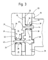
- the groove 24, the wall 21 is not over the entire Width of the bottom plate 16 extends approximately in their Middle through a chamber 33 in two about the same length groove-like depressions 34 and 35 divided, each groove-like recess 34, 35 of two parallel to each other extending straight groove walls 36 and 37 and one groove bottom 32 extending at right angles thereto that is also the top of the base plate 16 is.
- the chamber 33 is parallel and spaced from two chamber walls running at right angles to the groove walls 36, 37 38 limited, which mirror each other are.
- each of the Top edge 26 to the top of the bottom plate 16 are sufficient, are aligned insertion slots 39 included, which are in the middle of the concerned Groove 24 are located and at 41 clearly above the base plate 16 ends.
- the insertion slots 39 in the two Chamber walls 38 widen at their upper end funnel-shaped at 43.
- Chamber 33 has, in particular 3 shows, in the clearance profile the groove 24 has a somewhat larger width, measured in the longitudinal direction the groove 24 as in one to the left of the groove 24 lying chamber section 43.
- This chamber section 43 is also limited in parallel and extends up to down to the top of the bottom plate 16.
- slit 44 is in the direction of the groove 25 with a funnel-shaped Extension 45 provided and contains within the Wall 26 one from the top edge 26 to the top the base plate 16 extending extension.
- the slot 44 is symmetrical with respect to one Chamber section 43 symmetrically penetrating and on the bottom plate 16 vertical plane. Likewise is symmetrical about this plane in one Recess 46 in the wall 23 a rectangular, on all sides delimited opening 47.
- the width of the opening 47 corresponds the clear width of the slot 44, while the height is significantly less than the height of the remaining walls 21, 22 and 23 of the same height opening 47 goes smoothly into the top at the lower end the bottom plate 16 over.
- Finally the opening lies 47 symmetrically between the partition 28 and each adjacent sidewall 12. The distance that the Sidewall 12 of the partition 28 is larger than it corresponds to the width of the opening 47.
- Chamber 48 is present in the groove 25, and the chamber 48 is in the longitudinal direction of the groove 25 the chamber 33 offset.
- Chamber 48 is in similarly bounded by two chamber walls 38 which are designed in the same way as the chamber walls 38 of the chamber 33 and therefore the same reference numerals are used. They too are made by one Insertion slot 39 partially penetrated.
- chamber 48 has a chamber section 43 on, but in this case lies in the wall 46.
- the socket 1 contains two largely identical contact spring arrangements 49.
- the shown Contact spring assembly 49 is for use in the chamber 33 determined. It has a spring tongue 51, a connector 52 and an insulation displacement contact 53, which are all connected to one another in one piece.
- the insulation displacement contact 53 has the shape of a rectangular one Plate with a height of approx. 8 mm and one Thickness from about 0.3 to 0.5 mm. He is joined by two parallel edges 54 and 55 laterally and above and bounded below by two edges 56 and 57. The edge 57 is straight and parallel to edge 56. From the latter goes out an insulation displacement slot 58, which is parallel to edges 54 and 55 towards the lower edge 57 extends.
- the height of the insulation displacement contact 53, measured between the lower edge 57 and the upper edge 56, is slightly smaller than the height of the opening 47. Das against it has the lower end of the insulation displacement slot 58 from the lower edge 57 a smaller distance than the lower end 41 of the insertion slot 39 from the Top of the bottom plate 16.
- the connector 52 that the insulation displacement contact 53rd connects in one piece with the contact spring tongue 51 approximately L-shaped and consists of a lower leg 61, the lower edge of which merges flush with the lower edge 57 and an upper leg 62 that is rectangular is arranged to the leg 61.
- Between the two Legs 61 and 62 is approximately 45 ° Section 63 inserted, one of which is in the gusset area projecting between the legs 61 and 62 Extension 64 runs out.
- the height of the leg 61 is so dimensioned that it is significantly smaller than the distance of the lower end 41 of the insertion slot 39 from the Top of the bottom plate 16.
- the intermediate piece 63 has minus the extension 64 about the same thickness as the leg 61 and also the leg 62, which finally rises up at right angles and in the same Level lies like the insulation displacement contact 53, has one Thickness corresponding to leg 61.
- the adjoining the upper end of the leg 62 Contact spring tongue 51 is in the middle at 65 slightly V-shaped and its width is close to that Adjusted the length of the socket pins to be contacted, i.e. their width corresponds approximately to the clear width between the back of the front wall 6 and the inside of the rear cover 8.
- the contact spring tongue 51 goes in at its upper end a tab 66 with which the contact spring tongue 51st between corresponding ribs in the first housing leg 3 is held in a known manner.
- the extension 64 has an upper and a front edge 67 and 68 limits, the exact dimensions of which differ the following assembly description.
- the front edge 54 of the Insulation displacement contact 53 is low Distance from the opposite wall of the ventricular process 43. At the same time in this position lies in one level leading edge of the contact spring tongue 51 and the front edge extending therewith in extension of leg 62 on the back of the front wall 6 on. The upper edge 67 of the extension 64 against it lies with little play below the bottom of the Roof wall 27. The tab 66 is finally between corresponding Ribs tied up in the housing leg 3.
- the leg 61 leads of the connecting piece 52 lying bare through the groove 25 through. However, this happens in one Distance from the top edges 26 of the two walls 22 and 23 that contact is excluded. Also is through the section extending through the groove 25 of the leg 61 does not isolate one over it leading wire at risk because the top of the Leg 61 is significantly lower than the lower End of insertion slot 39.
- the invisible contact spring assembly 49 for the chamber 48 has, aside from the length of the leg 61, like already mentioned, the same shape as the contact spring arrangement shown 49.
- the length of the leg is 61 dimensioned so that when inserting this contact spring assembly into the other, invisible opening 47 of the Insulation displacement contact 53, as previously mentioned, in the chamber 48 comes to rest when the front edge 68 of the extension 64 and the front edge of the contact spring tongue 65 on the one hand on the back of the wall 23 and on the other hand Bump on the back of the front wall 6.
- both contact spring assemblies 49 slides these with their lower edge 57 free and without any Projections to be hindered on the top the base plate 16 into the associated chamber 33 or 48.
- Both contact spring assemblies 49 are in the assembled Condition with its lower edge 57 flat on the top the base plate 16, with the respective insulation displacement slot 58 centered in the insertion slot 39 of the stands two chamber walls 38. The lower end of the insulation displacement slot 58 disappears under the respective Chamber wall 38.
- the back cover 8 is the lower part of the first housing leg 3 and also the ones that follow Area of the second housing leg 4 is not covered and thus part of the leg 62 and the intermediate piece 63 lies bare, there is still no danger because the side walls 12 in connection with the two Partitions 28 ensure protection against contact.
- the rear edge of the leg 62 or the intermediate piece 63 jump opposite the trailing edges 29 or 31 so far back that at the given distance between the partition wall 28 and the adjacent side wall 12 the usual for checking the touch safety Ball does not reach the contact spring assembly 49 can.
- the new version is wired in such a way that with the help of a tool a non-stripped Head of suitable cross-section and outside diameter is pressed into the respective chamber 33 from above.
- the insulation displacement contact 53 cuts the insulation by the rest between the edges of the insertion slot 39 is only jammed.
- Assembly force is applied directly to the base plate 16 transfer. There are no forces that would strive the contact spring assembly 49 contrary to that mentioned above Insertion movement when mounting the socket 1 eject from the housing again. This result will be achieved in that the insulation displacement slot 38, the determines the direction of force when contacting, at right angles extends to the mounting direction in which the contact spring assembly 49 is inserted into the housing 2.
- the new solution can also are used for frames that are in a side Arm 71 a socket device 72 for a lamp starter exhibit.
- 4 has the second housing leg 4 the same shape as in the Embodiment according to FIGS. 1 to 3.
- the first housing leg 3 differs from the aforementioned embodiment only in that the side wall assembly 7 to form the mounting device 42 laterally is fully booked. Otherwise there is no difference.
- the version of FIG. 4 contains the Contact spring arrangement 49 according to FIG. 2.
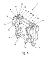
- the starter pin shows a top view in FIG. 5.
- the base plate 16 can thus be seen in FIG. 5, the two protruding parallel at a distance from each other Side walls 12, the partition walls arranged between them 28 and between each pair of a partition 28 and a side wall 12 located rectangular Openings 47.
- the contact spring assembly 73 differs from the second contact spring arrangement of the embodiment 2 in that the leg 62 just above the return 11 is turned to the right and thence as a straight tongue 74 to one of the two keyhole-like Openings 75 for the starter base pins leads.
- the tongue 74 runs just through the clearance profile the lower opening 75 and is through in the molded part 71 of the rear of the front wall 6 Last held 76.
- the tongue 74 lies over their entire length on the front wall 6 from the rear on.
- the second electrical connection between the one to be used Lamp and the starter happens through a Contact spring tongue 77, which is similar to the contact spring tongue 51 over the bore 13 extending portion 78 has that above the bore 13 after turns right into a straight section 79.
- this contact spring 77 are on the periphery the bore 13 corresponding ribs 81 provided between which section 78 passes through. His lower The end is in a pocket 82.
- the straight section 79 leads from the ribs 81 to a bend 83 and from there again as one another straight section 84 just through the clearance profile the upper opening 75.
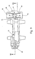
- FIG. 6 to 9 show a socket 1 which is provided for this purpose is a starter within a luminaire housing or other electrical equipment to hold corresponding socket pins. Also in this Traps are used for components made with components from the Fig. 1 to 3 or 5 and 6 are functionally the same Reference numerals used to indicate the homology between to recognize the components better.
- the version 1 according to FIGS. 6 to 9 consists of a one-piece housing 2, which has a front wall 87 as well has a rear wall 88 that extends between them Crosspieces 89 and side walls 90 are connected to one another are such that between the front and the Rear wall 87, 88 a sufficiently large space arises.
- the space is dimensioned so that if a starter with his socket pins through the keyhole shaped Openings 75 are inserted in the front wall 87 the free ends of the socket pins will not Bump on the inside of the rear wall 88.
- the two chambers 33 for two galvanically isolated insulation displacement contacts 58 provided.
- the two chambers 33 are exact mirror-symmetrical, so that the following description applies mutatis mutandis to both chambers 33.
- the one chamber wall 38 is from the Front wall 87 formed while the other rear Chamber wall 38 a cranked in the direction of the front wall 87 Area 88 is. Close both chamber walls 38 forward and backward collars 93 which the groove-shaped depressions 34 and 35 on both sides of the limit each chamber 33.
- the two collars 93 again form a continuous groove by the chamber 33 is interrupted.
- Embodiments lie with the embodiments 6 to 9, the axis of this of the groove-like Wells 34 and 35 defined groove perpendicular to the Front wall 27.
- the contact spring arrangements seated in the two chambers 33 58 are for the left and right sides of the Version 1 mirror-symmetrical. They already consist of the explained clamping cutting contact 53, the on his Bottom merges into a tab 95. From tab 95 a locking tongue 96 pointing upwards is released, which serves the clamp spring assembly 58 keep non-detachable in the associated chamber 33.
- the connector 52 is near the top edge 56 molded, which merges into the contact tongue 51.
- the Contact spring tongue 51 is a leaf spring strip, the Width equal to the clear distance between the front wall 87 and the rear wall is 88.
- the level of this contact spring tongue 51 stands vertically on the through the clamping cutting contact 53 defined level, i.e. she is like the top view at A shows L-shaped from the plane of the Clamping cutting contact 53 grounded out.
- each chamber 33 is pocket-shaped and picks up extension 95.
- the extension stands 95 with its lower edge 97 on a floor 98 of the Chamber 33 on.
- the latch snaps 96 in a corresponding opening 99 near the lower floor 98 of the respective chamber 33. Since the Locking tongue 96 is directed upwards, is after Locking the latching tongue 96 pulling out the contact spring arrangement 58 prevented upwards press-in force that occurs during contact, when the conductor into the insulation displacement slot 58 is pressed directly from the bottom 98 on the Transfer housing 2.
- the version 1 has an L-shaped seen from the side Housing 2 on that connected by two Housing legs 3 and 4 is formed.
- the first housing leg 3 consists of a side wall arrangement 7, to which a rear wall 102 is integrally formed this time is.
- the front wall 6 with the one inserted therein Rotating body 15 designed as a snap-on cover.
- grooved webs 106 go out are integrally formed on the bottom part 104.
- In these Webs 106 are groove-shaped slots.
- the two contact spring arrangements 49 for the two different ones Socket pins only differ at the distance that the insulation displacement contact 53 from the predetermined bending point 101.
- the housing 2 of the socket 1 is made of a thermoplastic Plastic material in one piece except as Injected lid trained front 6, namely in the position recognizable in FIG. 10.
- the protrude two bottom strips 105 of the second housing leg 4, based on the rear wall 102, of this rectangular up.
- the bottom part extending in between 104 is in the extension of the rear wall 102, i.e. the film hinge 103 is stretched.
- the slots contained in the webs 106 which as Straight sheet metal stampings made contact spring arrangements 49 inserted, so that from a Contact spring arrangement 49 of the insulation displacement contact 53 in the Chamber 48 and the other contact spring assembly 49th the insulation displacement contact 53 in the other chamber 33 lies.
Landscapes
- Connecting Device With Holders (AREA)
- Coupling Device And Connection With Printed Circuit (AREA)
- Connector Housings Or Holding Contact Members (AREA)
- Dry Shavers And Clippers (AREA)
- Fire-Detection Mechanisms (AREA)
Claims (42)
- Socle (1) pour des appareils électriques, tel que des lampes à décharge gazeuse, des lampes à incandescence ou des starters,avec un boítier (2) en matériau isolant;avec au moins une lame de contact élastique (51) disposée dans le boítier (2), qui est agencée de manière à réaliser le contact avec un contact prévu sur l'appareil;avec au moins un contact autodénudant (53) essentiellement en forme de plaquette logé dans le boítier (2), accessible de l'extérieur, pourvu d'une fente de contact (58) ouverte sur le côté pour l'insertion et le serrage d'une ligne d'alimentation, qui présente une largeur assurant une fixation par serrage d'un conducteur d'une ligne insérée;avec une pièce de liaison (52) électro-conductrice disposée entre la lame de contact élastique (51) et le contact autodénudant (53), la lame de contact élastique (51), le contact autodénudant (53) et la pièce de liaison (52) étant liés les uns aux autres en un élément monobloc et formant un système de lame de contact élastique (58);avec au moins une chambre (33, 48) pour le contact autodénudant (53) aménagée dans le boítier (2), chambre qui comporte dans ses parois (38) des fentes d'insertion (39) ouvertes sur le côté et orientées en direction de la fente de contact (58), dans laquelle le contact autodénudant (53) est logé en étant protégé contre les contacts involontaires et sur le fond (16, 98) de laquelle le contact autodénudant (53) prend appui, c'est-à-dire sur le fond (16, 98) de laquelle se dresse le contact autodénudant etavec des cloisons de protection (36, 37) qui sont disposées de chaque côté de la fente d'insertion (39) et forment des cavités (34, 35) en forme de rainures, qui s'étendent en direction des fentes d'insertion (39) et servent de protection contre les contacts involontaires pour une extrémité de conducteur éventuellement non isolée faisant saillie hors de la fente de contact (53).
- Socle selon la revendication 1, caractérisé en ce que la largeur de la cavité (34, 35) en forme de rainure est supérieure au diamètre extérieur d'une ligne à connecter.
- Socle selon la revendication 1, caractérisé en ce que la cavité (34, 35) en forme de rainure est plus profonde que la fente d'insertion (39)
- Socle selon la revendication 1, caractérisé en ce que la fente d'insertion (39) présente des arêtes vives.
- Socle selon la revendication 1, caractérisé en ce que la fente de contact (58) s'élargit en entonnoir au niveau de son extrémité ouverte.
- Socle selon la revendication 1, caractérisé en ce que la fente de d'insertion (39) s'élargit en entonnoir au niveau de son extrémité ouverte.
- Socle selon la revendication 1, caractérisé en ce que le boítier (2) présente des moyens de fixation (17, 18, 19) venus de moulage.
- Socle selon la revendication 1, caractérisé en ce que le boítier (2) présente une première aile et une seconde aile de boítier (3, 4) qui sont liées l'une à l'autre en une pièce monobloc, en ce que le boítier (2), vu de côté, a sensiblement la forme d'un L et en ce que les axes longitudinaux des ailes de boítier (3, 4) sont mutuellement perpendiculaires.
- Socle selon la revendication 8, caractérisé en ce que la première aile de boítier (3), dans sa paroi frontale (6) voisine de la seconde aile de boítier (4), comporte au moins une ouverture (13) pour le culot ou des broches de culot de l'appareil électrique.
- Socle selon la revendication 9, caractérisé en ce qu'un corps tournant (15) destiné à recevoir une lampe à culot à deux broches est monté tournant dans la paroi frontale (6).
- Socle selon la revendication 8, caractérisé en ce que la chambre (33, 48) au nombre d'au moins une pour le contact autodénudant (53) est prévue dans la seconde aile de boítier (4).
- Socle selon la revendication 11, caractérisé en ce que la seconde aile de boítier (4) comporte deux chambres (33, 48) pour deux contacts autodénudants (53), en ce que les cavités (34, 35) en forme de rainures (34, 35) qui font suite aux chambres (33, 48) définissent deux rainures (24, 25) ouvertes à leur extrémité dotées d'une largeur qui évolue dans la direction longitudinale et dont les axes longitudinaux sont perpendiculaires à l'axe longitudinal de la seconde aile de boítier (4), en ce que les rainures (34, 35) sont distantes l'une de l'autre et en ce que les deux chambres (33, 48), vu dans la direction longitudinale des rainures (24, 25), sont mutuellement décalées
- Socle selon la revendication 12, caractérisé en ce que la rainure (25) la plus proche de la paroi frontale (6) comporte, dans le prolongement de la chambre (33) dans l'autre rainure (24), dans ses deux parois latérales (36, 37), des ouvertures (44, 47) par lesquelles le contact autodénudant (53) peut être introduit dans sa chambre (33) concernée depuis la première aile de boítier (3).
- Socle selon la revendication 13, caractérisé en ce que les ouvertures (47) sont adaptées au profil en section transversale du contact autodénudant (53).
- Socle selon la revendication 13, caractérisé en ce que la chambre (33) et la rainure (25) voisine présentent des fonds qui sont situés à la même hauteur et en ce que les ouvertures (44, 47) au niveau du bord concerné, se raccordent sans décrochement au fond.
- Socle selon la revendication 13, caractérisé en ce que la seconde aile de boítier (4), dans la zone entre la paroi frontale (6) et la rainure (25) proche de celle-ci présente un fond (16) qui se raccorde sans décrochement aux fonds de la rainure (24) voisine et de la chambre (33) située de l'autre côté de la rainure (24).
- Socle selon la revendication 11, caractérisé en ce que la chambre (48) dans la rainure (25) proche de la paroi frontale (6) présente une ouverture (47) qui s'ouvre en direction de la première aile de boítier (3) de telle sorte que le contact autodénudant (53) concerné puisse être introduit dans sa chambre (33) à partir de la première aile de boítier (3).
- Socle selon la revendication 17, caractérisé en ce que la seconde aile de boítier (4), dans la zone entre la paroi frontale et la rainure (25) voisine de celle-ci, présente un fond (16) qui se raccorde sans décrochement au fond de la chambre (48) concernée.
- Socle selon la revendication 1, caractérisé en ce que la première aile de boítier (3), dans le prolongement des ouvertures (47, 44), dans la rainure (25) voisine de la paroi frontale est ouverte et en ce qu'au moins une paroi de séparation (28) qui s'étend en direction de la face arrière éloignée de la paroi frontale (6) de la première aile de boítier (3) est disposée entre les ouvertures (47, 44), laquelle paroi de séparation forme avec des parties de parois latérales (12) de la première et de la seconde aile de boítier (3, 4) des cavités en forme de rainures servant de protection contre les contacts involontaires.
- Socle selon la revendication 19, caractérisé en ce qu'il est prévu deux parois de séparation (28) distantes l'une de l'autre qui forment avec des parties de parois latérales (12) de la première et de la seconde aile de boítier (3, 4) des cavités en forme de rainures servant de protection contre les contacts involontaires.
- Socle selon la revendication 19 ou 20, caractérisé en ce que les parties de parois latérales (12) et les cloisons (28) sont pourvues de nervures qui mènent en entonnoir aux ouvertures (44, 47).
- Socle selon la revendication 8, caractérisé en ce que la première aile de boítier (3) comporte une partie de fond (104) qui est liée par une charnière film (104) à la première aile de boítier (3) et forme une pièce avec celle-ci et en ce que les chambres (33, 48) et les cavités (34, 35) en forme de rainures sont disposées dans la partie de fond (104).
- Socle selon la revendication 22, caractérisé en ce que des cloisons s'étendent depuis les chambres (33, 48) en direction d'une face arrière (102) de la première aile de boítier (3) éloignée de la paroi frontale (6), cloisons dans lesquelles sont aménagées des rainures ouvertes vers le haut dans lesquelles est logée une partie (52) du système de lame de contact élastique (58) concerné.
- Socle selon la revendication 23, caractérisé en ce que la première aile de boítier (3) est fermée au niveau de sa face arrière (102).
- Socle selon la revendication 8, caractérisé en ce qu'il est prévu sur la première aile de boítier (3) sur le côté de celle-ci un prolongement de boítier (71) qui comporte un dispositif de socle (72) supplémentaire.
- Socle selon la revendication 25, caractérisé en ce que le dispositif de socle (72) supplémentaire est un dispositif de socle de starter.
- Socle selon la revendication 1, caractérisé en ce que le boítier (2) a essentiellement la forme d'un parallélépipède avec une paroi frontale (87), une paroi arrière (88) et des parois latérales (90) et en ce qu'au moins une ouverture (75) pour le culot ou pour des broches de culot de l'appareil électrique est aménagée dans la paroi frontale (87).
- Socle selon la revendication 27, caractérisé en ce qu'au moins une chambre (33) est aménagée dans une des parois latérales (90).
- Socle selon la revendication 28, caractérisé en ce que deux chambres (33) sont aménagées dans l'une des cloisons latérales (90) dans le voisinage des angles concernés.
- Socle selon la revendication 27, caractérisé en ce que les cavités en forme de rainures (34, 35) traversent la paroi frontale (87) et/ou la paroi arrière (88).
- Socle selon la revendication 1, caractérisé en ce que la ou les fentes d'insertion (39) s'ouvrent dans une direction éloignée des moyens de fixation (17, 18, 19).
- Socle selon la revendication 1, caractérisé en ce que le système de lame de contact élastique (49, 58) est une pièce découpée en tôle.
- Socle selon la revendication 1, caractérisé en ce que le système de lame de contact élastique (49, 58) a essentiellement une forme de L.
- Socle selon la revendication 1, caractérisé en ce que la fente de contact (58) est orientée dans la même direction que la lame de contact élastique (51).
- Socle selon la revendication 1, caractérisé en ce que la pièce de liaison (52) comporte deux ailes (61, 62) mutuellement à angle droit et est conformée en biais au niveau du point de jonction (63).
- Socle selon la revendication 35, caractérisé en ce qu'il est prévu dans la région de l'angle de la forme en L une saillie (64) dont le bord (67) tourné vers la lame de contact élastique (51) est situé plus haut qu'une ouverture de la fente de contact (58) par rapport à un bord arrière (57) du contact autodénudant (53) .
- Socle selon la revendication 1, caractérisé en ce que la lame de contact élastique (51) est située sensiblement dans le même plan que le contact autodénudant (53).
- Socle selon la revendication 1, caractérisé en ce que la lame de contact élastique (51) est située dans un plan qui est sensiblement perpendiculaire au plan dans lequel se trouve le contact autodénudant (53).
- Socle selon la revendication 1, caractérisé en ce que la pièce de liaison (52) se raccorde au contact autodénudant (53) dans une zone dudit contact autodénudant (53) voisine de l'extrémité ouverte de la fente de contact (58).
- Socle selon la revendication 1, caractérisé en ce que la pièce de liaison (52) comporte une zone de pliage (101) qui permet de plier le système de lame de contact élastique (49) suivant un axe de pliage qui est perpendiculaire aux plans définis par les faces plates du contact autodénudant (53).
- Socle selon les revendications 22 et 40, caractérisé en ce que le point de pliage (101) est situé à proximité de la charnière film (103) lorsque le système de lame de contact élastique (49) est monté.
- Socle selon les revendications 1 et 12, caractérisé en ce que la pièce de liaison (52), au point où elle coupe un autre système de lame de contact élastique, est agencée de manière telle que son bord supérieur par rapport au fond (16) de la rainure (25) soit situé plus bas que l'extrémité inférieure de la fente de contact (58) de l'autre système de lame de contact élastique (49).
Applications Claiming Priority (2)
| Application Number | Priority Date | Filing Date | Title |
|---|---|---|---|
| DE4312776A DE4312776C2 (de) | 1993-04-20 | 1993-04-20 | Fassung für elektrische Betriebsmittel |
| DE4312776 | 1993-04-20 |
Publications (3)
| Publication Number | Publication Date |
|---|---|
| EP0621661A2 EP0621661A2 (fr) | 1994-10-26 |
| EP0621661A3 EP0621661A3 (fr) | 1996-05-08 |
| EP0621661B1 true EP0621661B1 (fr) | 1998-03-04 |
Family
ID=6485849
Family Applications (1)
| Application Number | Title | Priority Date | Filing Date |
|---|---|---|---|
| EP94100832A Expired - Lifetime EP0621661B1 (fr) | 1993-04-20 | 1994-01-21 | Socle pour appareillage électrique |
Country Status (8)
| Country | Link |
|---|---|
| US (1) | US5931691A (fr) |
| EP (1) | EP0621661B1 (fr) |
| JP (1) | JP3929506B2 (fr) |
| AT (1) | ATE163809T1 (fr) |
| AU (1) | AU678816B2 (fr) |
| DE (2) | DE4312776C2 (fr) |
| ES (1) | ES2113001T3 (fr) |
| SG (1) | SG67288A1 (fr) |
Cited By (2)
| Publication number | Priority date | Publication date | Assignee | Title |
|---|---|---|---|---|
| US8123540B2 (en) | 2008-10-01 | 2012-02-28 | Leviton Manufacturing Co., Inc. | Lamp socket having a rotor assembly |
| US8333602B2 (en) | 2011-01-06 | 2012-12-18 | Leviton Manufacturing Co., Inc. | Lamp socket having a rotor |
Families Citing this family (20)
| Publication number | Priority date | Publication date | Assignee | Title |
|---|---|---|---|---|
| DE19546797A1 (de) * | 1995-12-14 | 1997-06-19 | Amp Gmbh | Anordnung zur Kontaktierung, insbesondere zur Kontaktierung von Gasentladungslampen |
| DE19603374C2 (de) * | 1996-01-31 | 2000-12-07 | Vossloh Schwabe Gmbh | Selbstkontaktierende Fassung |
| DE19615372C2 (de) * | 1996-04-19 | 1998-07-16 | Vossloh Schwabe Gmbh | Montagekasten mit einer Lampenfassung für Zweistift-Leuchtstofflampen oder dergleichen |
| DE19615373C2 (de) * | 1996-04-19 | 1998-07-02 | Vossloh Schwabe Gmbh | Fassung, insbesondere für stabförmige Leuchtstoffröhren |
| DE29611509U1 (de) * | 1996-07-02 | 1996-09-05 | NORKA Norddeutsche Kunststoff- und Elektro-Gesellschaft Stäcker & Co. mbH, 22335 Hamburg | Leuchte für stabförmige, insbesondere zweiseitig gesockelte Leuchtstofflampen |
| DE19738461C2 (de) * | 1997-09-03 | 1999-09-23 | Vossloh Schwabe Gmbh | Federnd gelagerte Lampenfassung |
| DE19745762C1 (de) * | 1997-10-16 | 1999-08-26 | Vossloh Schwabe Gmbh | Leuchtstofflampenfassung mit verbesserter Stiftabstützung |
| DE19920116C2 (de) * | 1999-05-03 | 2002-06-20 | Vossloh Schwabe Gmbh | Starterfassung |
| DE10055148C2 (de) * | 2000-11-07 | 2003-05-22 | Phoenix Contact Gmbh & Co | Kabelanschluß- oder -verbindungseinrichtung |
| JP3982996B2 (ja) * | 2001-01-12 | 2007-09-26 | 矢崎総業株式会社 | ランプソケット及びソケットアセンブリ |
| US7403999B2 (en) * | 2001-12-28 | 2008-07-22 | International Business Machines Corporation | Classification support system and method for fragmented IP packets |
| US7597575B2 (en) | 2005-09-13 | 2009-10-06 | Leviton Manufacturing Co., Inc. | Fluorescent lampholder |
| US20090196029A1 (en) * | 2008-02-05 | 2009-08-06 | Richard Kurtz | Discharge lamp and fixture therefor |
| US7549787B1 (en) | 2008-04-01 | 2009-06-23 | Lee Blaymore | Pivoting lock mechanism for fluorescent lamp sockets |
| US8113684B2 (en) | 2008-07-15 | 2012-02-14 | Leviton Manufacturing Co., Inc. | Fluorescent lamp support |
| US20110164414A1 (en) * | 2008-07-15 | 2011-07-07 | Robert Quercia | Fluorescent lamp support |
| USD634274S1 (en) * | 2009-04-21 | 2011-03-15 | A.A.G. Stucchi S.R.L. | Lamp socket |
| DE102009003874B3 (de) * | 2009-05-04 | 2010-12-02 | Vossloh-Schwabe Deutschland Gmbh | Lampenfassung mit innerem Schalter |
| CN103081256B (zh) * | 2010-09-27 | 2015-10-07 | 东芝照明技术株式会社 | 灯座及照明装置 |
| US20160178169A1 (en) * | 2013-03-11 | 2016-06-23 | Koninklijke Philips N.V. | Adapter device for retrofitting in lighting arrangements |
Family Cites Families (17)
| Publication number | Priority date | Publication date | Assignee | Title |
|---|---|---|---|---|
| DE1137137B (de) * | 1954-01-11 | 1962-09-27 | Licentia Gmbh | Einklappbare Fassung fuer roehrenfoermige Lampen, insbesondere Leuchtstofflampen |
| DE1020113B (de) * | 1954-03-15 | 1957-11-28 | Licentia Gmbh | Umklappbare Fassung geringer axialer Tiefe fuer zweisockelige roehrenfoermige Lampen, insbesondere Leuchtstofflampen |
| US3337837A (en) * | 1964-04-06 | 1967-08-22 | Gen Electric | Electric connector with torsion contacts |
| NL6617061A (fr) * | 1966-12-03 | 1968-06-04 | ||
| DE1955977U (de) * | 1966-12-24 | 1967-02-23 | Broekelmann Jaeger & Busse K G | Starterfussung. |
| US3654587A (en) * | 1970-01-15 | 1972-04-04 | Westinghouse Electric Corp | Fluorescent lampholder or the like |
| ES179115Y (es) * | 1972-04-08 | 1973-11-16 | Amp, Incorporated | Un elemento de contacto de chapa metalica. |
| CA981352A (en) * | 1972-04-08 | 1976-01-06 | Roberto Plana | Electrical connectors |
| DE2559818C3 (de) * | 1975-04-15 | 1983-01-05 | Brökelmann, Jaeger & Busse GmbH & Co, 5760 Arnsberg | Fassung für Leuchtstofflampen und Verfahren zu ihrer Herstellung |
| CH652866A5 (de) * | 1981-11-04 | 1985-11-29 | Schurter Ag | Lampenfassung fuer gluehlampen mit edisongewinde. |
| GB2114822A (en) * | 1982-02-10 | 1983-08-24 | Egyesuelt Izzolampa | Resilient socket for an electric light source |
| US4807098A (en) * | 1984-10-24 | 1989-02-21 | Ahroni Joseph M | Lampholders for miniature light sets |
| US5121310A (en) * | 1984-10-24 | 1992-06-09 | Ahroni Joseph M | Chaser decorative light set |
| DE3818517C2 (de) * | 1988-05-31 | 1995-01-12 | Siemens Ag | Lampenfassung |
| DE8913917U1 (de) * | 1989-11-25 | 1991-03-21 | Parol Leuchtenkomponenten GmbH, 4000 Düsseldorf | Fassung für eine Niederdruckleuchtstofflampe |
| DE4108390C1 (en) * | 1991-03-15 | 1992-03-12 | Hella Kg Hueck & Co, 4780 Lippstadt, De | Vehicle lamp fitting with several bulbs - has multiple plug connection consisting of several conducting tracks and housed in insulating part |
| DE4218740C2 (de) * | 1992-06-06 | 1995-07-06 | Vossloh Schwabe Gmbh | Elektrische Anschlußklemmeinrichtung |
-
1993
- 1993-04-20 DE DE4312776A patent/DE4312776C2/de not_active Expired - Fee Related
-
1994
- 1994-01-21 DE DE59405331T patent/DE59405331D1/de not_active Expired - Lifetime
- 1994-01-21 EP EP94100832A patent/EP0621661B1/fr not_active Expired - Lifetime
- 1994-01-21 AT AT94100832T patent/ATE163809T1/de active
- 1994-01-21 ES ES94100832T patent/ES2113001T3/es not_active Expired - Lifetime
- 1994-01-21 SG SG1996001247A patent/SG67288A1/en unknown
- 1994-04-19 AU AU60568/94A patent/AU678816B2/en not_active Ceased
- 1994-04-20 JP JP08188394A patent/JP3929506B2/ja not_active Expired - Fee Related
-
1996
- 1996-08-21 US US08/701,198 patent/US5931691A/en not_active Expired - Fee Related
Cited By (2)
| Publication number | Priority date | Publication date | Assignee | Title |
|---|---|---|---|---|
| US8123540B2 (en) | 2008-10-01 | 2012-02-28 | Leviton Manufacturing Co., Inc. | Lamp socket having a rotor assembly |
| US8333602B2 (en) | 2011-01-06 | 2012-12-18 | Leviton Manufacturing Co., Inc. | Lamp socket having a rotor |
Also Published As
| Publication number | Publication date |
|---|---|
| AU678816B2 (en) | 1997-06-12 |
| ATE163809T1 (de) | 1998-03-15 |
| EP0621661A2 (fr) | 1994-10-26 |
| DE4312776A1 (de) | 1994-12-08 |
| AU6056894A (en) | 1994-10-27 |
| ES2113001T3 (es) | 1998-04-16 |
| DE4312776C2 (de) | 1995-08-31 |
| JP3929506B2 (ja) | 2007-06-13 |
| EP0621661A3 (fr) | 1996-05-08 |
| JPH07122338A (ja) | 1995-05-12 |
| DE59405331D1 (de) | 1998-04-09 |
| SG67288A1 (en) | 1999-09-21 |
| US5931691A (en) | 1999-08-03 |
Similar Documents
| Publication | Publication Date | Title |
|---|---|---|
| EP0621661B1 (fr) | Socle pour appareillage électrique | |
| EP0678932B1 (fr) | Borne de raccordement et de connexion électrique | |
| EP2672576B1 (fr) | Connecteur pour la transmission de données par des fils électriques | |
| DE3320440C2 (de) | Elektrischer Verbinder | |
| EP0758808B1 (fr) | Sytème de douille de lampe pour lampes fluorescentes | |
| DE2414640A1 (de) | Elektrische anschlussklemme | |
| DE2212807C2 (de) | Elektrische Verbinderanordnung | |
| DE3009675C2 (fr) | ||
| EP0311769A2 (fr) | Fiche à contacts et à ressort miniaturisée | |
| DE202019105009U1 (de) | Leiteranschlussklemme | |
| DE2536135A1 (de) | Elektrische verbindungsanordnung | |
| DE3928751C2 (fr) | ||
| DE3345128C2 (fr) | ||
| DE19949387B4 (de) | Kontaktteil für Anschlussklemme | |
| DE4312781C2 (de) | Anschlußelement für wenigstens ein elektrisches Betriebsmittel | |
| DE3224954A1 (de) | Steckkarten-sockel | |
| EP3849018B1 (fr) | Borne de raccordement de conducteur | |
| EP0220394A2 (fr) | Connecteur électrique | |
| DE202005014577U1 (de) | Anschlussklemme für eine Sammelschiene | |
| DE102014114352B3 (de) | Stiftleiste | |
| DE2346072A1 (de) | Anschlussklemme fuer eine elektrische verbindung | |
| EP0568899B1 (fr) | Prise de câble multipolaire | |
| EP0892997B1 (fr) | Connecteur a fiches pour cables | |
| DE3306219C2 (de) | Schalter, insbesondere für Kraftfahrzeuge | |
| DE3030906C2 (de) | Umschaltsteckvorrichtung mit einem Brückenstecker |
Legal Events
| Date | Code | Title | Description |
|---|---|---|---|
| PUAI | Public reference made under article 153(3) epc to a published international application that has entered the european phase |
Free format text: ORIGINAL CODE: 0009012 |
|
| AK | Designated contracting states |
Kind code of ref document: A2 Designated state(s): AT CH DE ES FR GB IT LI NL SE |
|
| PUAL | Search report despatched |
Free format text: ORIGINAL CODE: 0009013 |
|
| AK | Designated contracting states |
Kind code of ref document: A3 Designated state(s): AT CH DE ES FR GB IT LI NL SE |
|
| 17P | Request for examination filed |
Effective date: 19961009 |
|
| GRAG | Despatch of communication of intention to grant |
Free format text: ORIGINAL CODE: EPIDOS AGRA |
|
| GRAG | Despatch of communication of intention to grant |
Free format text: ORIGINAL CODE: EPIDOS AGRA |
|
| GRAH | Despatch of communication of intention to grant a patent |
Free format text: ORIGINAL CODE: EPIDOS IGRA |
|
| 17Q | First examination report despatched |
Effective date: 19970728 |
|
| GRAH | Despatch of communication of intention to grant a patent |
Free format text: ORIGINAL CODE: EPIDOS IGRA |
|
| GRAA | (expected) grant |
Free format text: ORIGINAL CODE: 0009210 |
|
| AK | Designated contracting states |
Kind code of ref document: B1 Designated state(s): AT CH DE ES FR GB IT LI NL SE |
|
| REF | Corresponds to: |
Ref document number: 163809 Country of ref document: AT Date of ref document: 19980315 Kind code of ref document: T |
|
| REG | Reference to a national code |
Ref country code: CH Ref legal event code: NV Representative=s name: KIRKER & CIE SA Ref country code: CH Ref legal event code: EP |
|
| GBT | Gb: translation of ep patent filed (gb section 77(6)(a)/1977) |
Effective date: 19980305 |
|
| REF | Corresponds to: |
Ref document number: 59405331 Country of ref document: DE Date of ref document: 19980409 |
|
| REG | Reference to a national code |
Ref country code: ES Ref legal event code: FG2A Ref document number: 2113001 Country of ref document: ES Kind code of ref document: T3 |
|
| ITF | It: translation for a ep patent filed | ||
| ET | Fr: translation filed | ||
| PLBE | No opposition filed within time limit |
Free format text: ORIGINAL CODE: 0009261 |
|
| STAA | Information on the status of an ep patent application or granted ep patent |
Free format text: STATUS: NO OPPOSITION FILED WITHIN TIME LIMIT |
|
| 26N | No opposition filed | ||
| REG | Reference to a national code |
Ref country code: GB Ref legal event code: IF02 |
|
| NLT1 | Nl: modifications of names registered in virtue of documents presented to the patent office pursuant to art. 16 a, paragraph 1 |
Owner name: VOSSLOH-SCHWABE DEUTSCHLAND GMBH |
|
| REG | Reference to a national code |
Ref country code: CH Ref legal event code: PFA Owner name: VOSSLOH-SCHWABE DEUTSCHLAND GMBH Free format text: VOSSLOH SCHWABE GMBH#WASENSTRASSE 25#D-73660 URBACH (DE) -TRANSFER TO- VOSSLOH-SCHWABE DEUTSCHLAND GMBH#HOHE STEINERT 8#58509 LUEDENSCHEID (DE) |
|
| PGFP | Annual fee paid to national office [announced via postgrant information from national office to epo] |
Ref country code: SE Payment date: 20110113 Year of fee payment: 18 Ref country code: CH Payment date: 20110124 Year of fee payment: 18 Ref country code: AT Payment date: 20110113 Year of fee payment: 18 Ref country code: NL Payment date: 20110117 Year of fee payment: 18 |
|
| PGFP | Annual fee paid to national office [announced via postgrant information from national office to epo] |
Ref country code: FR Payment date: 20120206 Year of fee payment: 19 |
|
| PGFP | Annual fee paid to national office [announced via postgrant information from national office to epo] |
Ref country code: DE Payment date: 20120131 Year of fee payment: 19 |
|
| PGFP | Annual fee paid to national office [announced via postgrant information from national office to epo] |
Ref country code: GB Payment date: 20120120 Year of fee payment: 19 Ref country code: IT Payment date: 20120126 Year of fee payment: 19 |
|
| REG | Reference to a national code |
Ref country code: NL Ref legal event code: V1 Effective date: 20120801 |
|
| REG | Reference to a national code |
Ref country code: CH Ref legal event code: PL |
|
| REG | Reference to a national code |
Ref country code: SE Ref legal event code: EUG |
|
| PG25 | Lapsed in a contracting state [announced via postgrant information from national office to epo] |
Ref country code: SE Free format text: LAPSE BECAUSE OF NON-PAYMENT OF DUE FEES Effective date: 20120122 Ref country code: CH Free format text: LAPSE BECAUSE OF NON-PAYMENT OF DUE FEES Effective date: 20120131 Ref country code: LI Free format text: LAPSE BECAUSE OF NON-PAYMENT OF DUE FEES Effective date: 20120131 |
|
| REG | Reference to a national code |
Ref country code: AT Ref legal event code: MM01 Ref document number: 163809 Country of ref document: AT Kind code of ref document: T Effective date: 20120121 |
|
| PG25 | Lapsed in a contracting state [announced via postgrant information from national office to epo] |
Ref country code: AT Free format text: LAPSE BECAUSE OF NON-PAYMENT OF DUE FEES Effective date: 20120121 Ref country code: NL Free format text: LAPSE BECAUSE OF NON-PAYMENT OF DUE FEES Effective date: 20120801 |
|
| PGFP | Annual fee paid to national office [announced via postgrant information from national office to epo] |
Ref country code: ES Payment date: 20120126 Year of fee payment: 19 |
|
| GBPC | Gb: european patent ceased through non-payment of renewal fee |
Effective date: 20130121 |
|
| REG | Reference to a national code |
Ref country code: FR Ref legal event code: ST Effective date: 20130930 |
|
| PG25 | Lapsed in a contracting state [announced via postgrant information from national office to epo] |
Ref country code: DE Free format text: LAPSE BECAUSE OF NON-PAYMENT OF DUE FEES Effective date: 20130801 |
|
| REG | Reference to a national code |
Ref country code: DE Ref legal event code: R119 Ref document number: 59405331 Country of ref document: DE Effective date: 20130801 |
|
| PG25 | Lapsed in a contracting state [announced via postgrant information from national office to epo] |
Ref country code: FR Free format text: LAPSE BECAUSE OF NON-PAYMENT OF DUE FEES Effective date: 20130131 Ref country code: GB Free format text: LAPSE BECAUSE OF NON-PAYMENT OF DUE FEES Effective date: 20130121 |
|
| PG25 | Lapsed in a contracting state [announced via postgrant information from national office to epo] |
Ref country code: IT Free format text: LAPSE BECAUSE OF NON-PAYMENT OF DUE FEES Effective date: 20130121 |
|
| REG | Reference to a national code |
Ref country code: ES Ref legal event code: FD2A Effective date: 20140324 |
|
| PG25 | Lapsed in a contracting state [announced via postgrant information from national office to epo] |
Ref country code: ES Free format text: LAPSE BECAUSE OF NON-PAYMENT OF DUE FEES Effective date: 20130122 |