EP0621926B1 - Barre d'appui pour capot protecteur de toupies - Google Patents
Barre d'appui pour capot protecteur de toupies Download PDFInfo
- Publication number
- EP0621926B1 EP0621926B1 EP93924045A EP93924045A EP0621926B1 EP 0621926 B1 EP0621926 B1 EP 0621926B1 EP 93924045 A EP93924045 A EP 93924045A EP 93924045 A EP93924045 A EP 93924045A EP 0621926 B1 EP0621926 B1 EP 0621926B1
- Authority
- EP
- European Patent Office
- Prior art keywords
- head
- guide rail
- vertical groove
- adjusting screw
- plunger
- Prior art date
- Legal status (The legal status is an assumption and is not a legal conclusion. Google has not performed a legal analysis and makes no representation as to the accuracy of the status listed.)
- Expired - Lifetime
Links
- 230000001681 protective effect Effects 0.000 title claims abstract description 16
- 239000002023 wood Substances 0.000 title claims abstract description 7
- 238000007493 shaping process Methods 0.000 title claims abstract 3
- 235000001674 Agaricus brunnescens Nutrition 0.000 claims 1
- 238000003801 milling Methods 0.000 description 11
- 230000006835 compression Effects 0.000 description 4
- 238000007906 compression Methods 0.000 description 4
- 238000000034 method Methods 0.000 description 1
- 230000000149 penetrating effect Effects 0.000 description 1
Images



Classifications
-
- B—PERFORMING OPERATIONS; TRANSPORTING
- B27—WORKING OR PRESERVING WOOD OR SIMILAR MATERIAL; NAILING OR STAPLING MACHINES IN GENERAL
- B27G—ACCESSORY MACHINES OR APPARATUS FOR WORKING WOOD OR SIMILAR MATERIALS; TOOLS FOR WORKING WOOD OR SIMILAR MATERIALS; SAFETY DEVICES FOR WOOD WORKING MACHINES OR TOOLS
- B27G21/00—Safety guards or devices specially designed for other wood-working machines auxiliary devices facilitating proper operation of said wood-working machines
-
- Y—GENERAL TAGGING OF NEW TECHNOLOGICAL DEVELOPMENTS; GENERAL TAGGING OF CROSS-SECTIONAL TECHNOLOGIES SPANNING OVER SEVERAL SECTIONS OF THE IPC; TECHNICAL SUBJECTS COVERED BY FORMER USPC CROSS-REFERENCE ART COLLECTIONS [XRACs] AND DIGESTS
- Y10—TECHNICAL SUBJECTS COVERED BY FORMER USPC
- Y10T—TECHNICAL SUBJECTS COVERED BY FORMER US CLASSIFICATION
- Y10T403/00—Joints and connections
- Y10T403/70—Interfitted members
- Y10T403/7062—Clamped members
- Y10T403/7064—Clamped members by wedge or cam
- Y10T403/7066—Clamped members by wedge or cam having actuator
Definitions
- the invention relates to a stop bar with a clamping element for height-adjustable fastening in a cross-sectionally C-shaped vertical groove of a protective hood for wood milling machines, the clamping element having a plunger with a mushroom-shaped head and being clampable in the vertical groove by means of an adjusting screw.
- protective hoods which consist of two side walls connected by a rear wall, a height-adjustable front protective shield and a cover on which a connection opening for a suction device is provided.
- a connection opening for a suction device is provided in the front edges of the side walls.
- vertical grooves are incorporated, which are used for the height-adjustable reception of a stop bar or the like.
- the clamping element is a clamping piece, not specified in its shape, which is held on an angle piece by means of a screw. After loosening the screw, the angle piece can be adjusted in height, whereby the clamping piece slides within the C-shaped groove. When the desired height is reached, the screw must be tightened again. Since this is in the area of the inside of the protective hood, it is relatively difficult to access and can only be removed after removing a transparent one Protective shield are operated.
- the stop bar On the horizontal leg of the contra-angle handpiece, the stop bar is fastened with the help of two further screws, which can only be adjusted in its longitudinal direction after loosening the two screws, which are also only accessible after removing the protective shield.
- the settings described can only be carried out for milling tools with a large diameter if the tool has also been removed beforehand, because only then is the necessary access to the internal screws available.
- the stop bar When working with an arc milling stop, the stop bar must be unscrewed.
- the invention has for its object to design a stop bar with clamping element so that it can be adjusted with simple, easily accessible means and without the aid of tools and, if necessary, can be brought into a rest position in which it remains connected to the protective hood.
- the head consists of two circular disk-shaped head parts which can be displaced relative to one another by means of the adjusting screw and can be expanded against the groove walls of the vertical groove.
- This solution has the essential advantage that after loosening only a single control element - the set screw - at least two adjustment processes can be carried out, namely a height adjustment of the stop bar and a swiveling of the stop bar upwards.
- the circular disk-shaped head parts allow the stop bar to come off their horizontal working position can be rotated into a vertical rest position and clamped there again without having to be removed from the protective hood.
- a square locking body is formed on the underside of the fixed head part facing the stop strip, which engages in the respective positions between the boundary edges of the vertical groove.
- the stamp can be moved and clamped in a recess in the stop bar by means of the adjusting screw penetrating an elongated hole in the stop bar.
- This has the advantage that a further adjustment position can be fixed by means of the single adjusting screw, namely the optimal adjustment of the stop bar to a stop ring.
- the run-up bar can both be moved in the direction of the elongated hole and rotated around the axis of the set screw.
- a horizontal machine table 10 of a wood milling machine is indicated, on which a protective hood 12 is fixed, which covers the working area of a milling tool 16 attached to a spindle 14.
- the protective hood consists of two side walls 18, a rear wall 20 connecting them and a cover 22 which is firmly connected to the rear wall 20.
- An edge 24 protrudes downward and laterally from the cover 22 and has an opening 26 in the front area which is open at the bottom and which increases the view into the interior of the protective hood 12.
- the cover 22 has a nozzle 28 in its rear area for connecting a suction device.
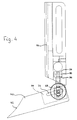
- each side wall 18 In the forward-facing edge regions 30 of each side wall 18, vertical grooves 32 are incorporated, which have an approximately C-shaped cross section, which can be seen in FIG. 4. In this way, a rear boundary surface 34 and two front clamping surfaces 36 are formed in the vertical groove 32. The lower end of each vertical groove 32 is open, but can be closed by a closing element, not shown.
- a thrust ring 38 which is mounted on the spindle 14 by means of a ball bearing, is used to guide an arcuate workpiece to be machined by means of the milling tool 16.
- a stop bar 40 is provided, the free, curved end 42 of which rests on the outer circumference of the stop ring 38.
- the stop bar 40 which can be made of plastic, has a slot-shaped recess 44 at its end opposite the free end 42 and is fastened in the vertical groove 32 on the right in FIGS. 1 and 2 by means of a clamping element 46.
- the clamping element 46 consists of a punch 48 with a mushroom-shaped head 50.
- the head 50 itself consists of two head parts 52 and 54 which can be displaced relative to one another, both of which are designed as circular disks.
- the head part 52 lying at the free end of the head is screwed firmly onto the free end of a rod 56 which is mounted so as to be longitudinally displaceable within the stamp 48.
- the diameter of the free end 58 of the rod 56 corresponds to the bore diameter of the punch 48 and thereby forms a collar on which a compression spring 60 is supported. This endeavors to always pull the rod 56 and with it the head part 52 into the release position.
- the free end 58 of the rod 56 is designed as a conical tip 62, which is pressed by the compression spring 60 against a wedge 64, which is mounted in a slot-like recess 66 of the plunger 48 so that it can be adjusted radially to the latter.
- the inclined surface of the wedge 64 opposite the tip 62 bears against a corresponding inclined surface of the recess 66.
- the wedge 64 can be moved with the aid of an adjusting screw 68 in the vertical direction in FIG.
- the wedge 64 displaces the rod 56 against the force of the compression spring 60, so that the head part 52 is moved away from the head part 54.
- Characterized the two head parts 52 and 54 are spread against the boundary surface 34 and the clamping surface 36 within the vertical groove 32, so that finally the clamping element 46 and with this the stop bar 40 are fixed.
- the punch 48 is also clamped within the recess 44. Since the threaded shaft 70 of the adjusting screw 68 extends through an elongated hole 72 machined into the stop bar 40, the stop bar 40 can be adjusted in its longitudinal direction.
- the latching body 74 engages again between the boundary edges of the vertical groove 32, so that the stop bar 40 is fixed in its rest position, for example when work is carried out without a stop ring 38.
- the latching body 74 thus ensures at least two defined positions of the stop bar 40.
Landscapes
- Life Sciences & Earth Sciences (AREA)
- Engineering & Computer Science (AREA)
- Mechanical Engineering (AREA)
- Wood Science & Technology (AREA)
- Forests & Forestry (AREA)
- Milling, Drilling, And Turning Of Wood (AREA)
- Storage Of Harvested Produce (AREA)
- Chemical And Physical Treatments For Wood And The Like (AREA)
Claims (7)
- Barre d'appui avec un élément de blocage pour la fixation réglable en hauteur dans une rainure verticale d'une section en forme de C, d'un capot protecteur pour machines à fraiser le bois, l'élément de blocage présentant un poinçon avec une tête élargie en forme de champignon et pouvant être serré dans la rainure verticale à l'aide d'une vis de serrage, caractérisé par le fait que la tête (50) est composée de deux parties (52, 54) en forme de disque, décalables l'une par rapport à l'autre à l'aide de la vis de serrage (68) et qui peuvent être écartées contre les parois (34, 36) de la rainure verticale (32).
- Barre d'appui selon la revendication 1, caractérisée par le fait que sur le côté inférieur de la partie de tête fixe (54) dirigée vers la barre d'appui (40) se trouve un élément d'arrêt carré (74) qui engage entre les arêtes de limitation de la rainure verticale (32).
- Barre d'appui selon la revendication 1 ou 2, caractérisée par le fait que le poinçon (48) peut être déplacé et bloqué à l'aide de la vis de serrage (68) passant à travers une fente oblongue (72) de la barre d'appui (40) dans un creux (44) de la barre d'appui (40).
- Barre d'appui selon une des revendications précédentes, caractérisée par le fait que la partie de tête (52) à l'extrémité libre de la tête (50) est fixée à l'extrémité d'une barre (56) qui est logée dans le poinçon (48) de sorte qu'elle permet un déplacement longitudinal.
- Barre d'appui selon la revendication 4, caractérisée par le fait que l'extrémité (58) de la barre (56) à l'opposé de la partie de tête (52) s'appuie avec une face oblique (62) sur un coin (64) réglable de façon radiale à l'intérieur du poinçon (48).
- Barre d'appui selon la revendication 4 ou 5, caractérisée par le fait que la barre (56) est tirée à l'aide d'un ressort (60) en direction de la position de desserrage.
- Barre d'appui selon la revendication 5 ou 6, caractérisée par le fait que la vis de serrage (68) est vissée dans un filetage du coin (64).
Applications Claiming Priority (3)
| Application Number | Priority Date | Filing Date | Title |
|---|---|---|---|
| DE4238449 | 1992-11-13 | ||
| DE4238449A DE4238449C1 (de) | 1992-11-13 | 1992-11-13 | Anlaufleiste für eine Schutzhaube an Holzfräsmaschinen |
| PCT/EP1993/002943 WO1994011641A1 (fr) | 1992-11-13 | 1993-10-25 | Barre d'appui pour capot protecteur de toupies |
Publications (2)
| Publication Number | Publication Date |
|---|---|
| EP0621926A1 EP0621926A1 (fr) | 1994-11-02 |
| EP0621926B1 true EP0621926B1 (fr) | 1996-01-17 |
Family
ID=6472858
Family Applications (1)
| Application Number | Title | Priority Date | Filing Date |
|---|---|---|---|
| EP93924045A Expired - Lifetime EP0621926B1 (fr) | 1992-11-13 | 1993-10-25 | Barre d'appui pour capot protecteur de toupies |
Country Status (8)
| Country | Link |
|---|---|
| US (1) | US5555921A (fr) |
| EP (1) | EP0621926B1 (fr) |
| JP (1) | JPH07502948A (fr) |
| AT (1) | ATE133237T1 (fr) |
| DE (2) | DE4238449C1 (fr) |
| DK (1) | DK0621926T3 (fr) |
| ES (1) | ES2085173T3 (fr) |
| WO (1) | WO1994011641A1 (fr) |
Families Citing this family (6)
| Publication number | Priority date | Publication date | Assignee | Title |
|---|---|---|---|---|
| CH689971A5 (fr) * | 1994-05-04 | 2000-02-29 | Bobst Sa | Dispositif de centrage et de verrouillage d'un cadre porte-outils dans une presse de découpage. |
| ES2142638T3 (es) * | 1996-05-04 | 2000-04-16 | Georg Aigner | Barra de apoyo. |
| DE19617888C1 (de) * | 1996-05-04 | 1997-01-02 | Georg Aigner | Anlaufleiste |
| DE19701880C2 (de) * | 1997-01-21 | 1999-10-21 | Fried Kunststofftechnik Gmbh | Späneauffangvorrichtung |
| DE19900430C1 (de) * | 1999-01-08 | 2000-07-20 | Georg Aigner | Schutzhaube für Holzfräsmaschinen |
| US20080078471A1 (en) * | 2006-09-28 | 2008-04-03 | Eastway Fair Company Limited | Fence assembly with articulating bit guard |
Family Cites Families (10)
| Publication number | Priority date | Publication date | Assignee | Title |
|---|---|---|---|---|
| US1947885A (en) * | 1933-06-19 | 1934-02-20 | Delta Mfg Co | Work guide |
| US2104158A (en) * | 1935-05-02 | 1938-01-04 | Duro Metal Prod Co | Work guide for woodworking machines |
| FR2348012A1 (fr) * | 1976-04-14 | 1977-11-10 | Nanini Antoine | Dispositif de blocage d'une piece sur une table de machine-outil |
| US4547092A (en) * | 1984-02-21 | 1985-10-15 | Hamilton Industries | Accessory clamp for medical table |
| DE3444621A1 (de) * | 1984-12-07 | 1986-06-19 | A. Römheld GmbH & Co KG, 6312 Laubach | Befestigungselement zum verspannen von werkzeugen und paletten auf maschinentischen |
| AT385444B (de) * | 1985-07-16 | 1988-03-25 | Straka Roman | Werkstueckspannvorrichtung |
| DE8915933U1 (de) * | 1989-09-19 | 1992-04-09 | Fried Kunststofftechnik GmbH, 7068 Urbach | Spänefangvorrichtung für eine Tischfräsmaschine |
| US5117880A (en) * | 1990-10-16 | 1992-06-02 | Delta International Machinery Corporation | Shield for cutting blade |
| DE4131943C1 (fr) * | 1991-09-25 | 1992-09-17 | Georg 8386 Reisbach De Aigner | |
| DE4339953A1 (de) * | 1993-11-24 | 1995-06-01 | Weinig Michael Ag | Maschine zum Bearbeiten von Werkstücken aus Holz, Kunststoff und dergleichen |
-
1992
- 1992-11-13 DE DE4238449A patent/DE4238449C1/de not_active Expired - Fee Related
-
1993
- 1993-10-25 AT AT93924045T patent/ATE133237T1/de not_active IP Right Cessation
- 1993-10-25 EP EP93924045A patent/EP0621926B1/fr not_active Expired - Lifetime
- 1993-10-25 WO PCT/EP1993/002943 patent/WO1994011641A1/fr not_active Ceased
- 1993-10-25 DK DK93924045.3T patent/DK0621926T3/da active
- 1993-10-25 JP JP6511641A patent/JPH07502948A/ja active Pending
- 1993-10-25 ES ES93924045T patent/ES2085173T3/es not_active Expired - Lifetime
- 1993-10-25 DE DE59301476T patent/DE59301476D1/de not_active Expired - Fee Related
- 1993-10-25 US US08/244,801 patent/US5555921A/en not_active Expired - Fee Related
Also Published As
| Publication number | Publication date |
|---|---|
| DK0621926T3 (da) | 1996-03-18 |
| US5555921A (en) | 1996-09-17 |
| JPH07502948A (ja) | 1995-03-30 |
| WO1994011641A1 (fr) | 1994-05-26 |
| DE4238449C1 (de) | 1994-03-24 |
| EP0621926A1 (fr) | 1994-11-02 |
| ATE133237T1 (de) | 1996-02-15 |
| ES2085173T3 (es) | 1996-05-16 |
| DE59301476D1 (de) | 1996-02-29 |
Similar Documents
| Publication | Publication Date | Title |
|---|---|---|
| WO1994001242A1 (fr) | Element intermediaire pour dispositifs de serrage sur plaques a matrice de trous de machine-outil | |
| EP0558692B1 (fr) | Dispositif de protection et de guidage pour fraiseuses a bois--- | |
| EP0621926B1 (fr) | Barre d'appui pour capot protecteur de toupies | |
| EP0598079B1 (fr) | Capot de protection pour machines-outils a travailler le bois | |
| DE7825793U1 (de) | Metallbearbeitungsmaschine | |
| DE102005009227A1 (de) | Frästisch und Zubehör | |
| DE4406597A1 (de) | Vorrichtung zum Herstellen von Wandausnehmungen | |
| EP0533093A2 (fr) | Moyens de serrage à variation continue | |
| EP3149347A1 (fr) | Dispositif de fixation servant à fixer un objet sur une paroi et système de fixation | |
| DE29521059U1 (de) | Beschlag zum Montieren und Ausrichten einer Frontblende an einen Schubkasten o.dgl. | |
| EP0805007B1 (fr) | Barre d'appui | |
| DE1477355A1 (de) | Werkzeughalter fuer Schneidwerkzeuge | |
| DE29902343U1 (de) | Schleifvorrichtung für Bohrer | |
| DE9014657U1 (de) | Nutstoßmaschine | |
| DE3930682A1 (de) | Fuehrungstisch fuer tragbare fraesmaschinen | |
| EP1306504B1 (fr) | Elément de support pour paumelle de dispositif d'arrêt de porte reglable en direction transversale ou de l'épaisseur de la porte sur un profilé creux, tel que profilé en aluminium | |
| DE19739269C1 (de) | Spannvorrichtung, insbesondere Maschinenschraubstock | |
| DE3637485C2 (fr) | ||
| WO1988005359A1 (fr) | Dispositif pour relier deux pieces configurees de maniere a etre sensiblement symetriques en rotation dans la region de liaison, notamment une tete d'outil avec un porte-outil dans des machines-outils | |
| DE3431110C2 (fr) | ||
| DE828035C (de) | Maschine zum Nachbearbeiten von Massenfertigungsteilen, insbesondere zum Schlitzen von Schrauben | |
| DE7227912U (de) | Stanzwerkzeughalter an Stanzpressen | |
| DE29810720U1 (de) | Spannbackenhalterung | |
| EP0570605B1 (fr) | Dispositif protecteur pour raboteuse | |
| DE2534378B2 (de) | Vorrichtung zur Kraftschlüssigen Verbindung eines verschwenkbaren Gipsmodell-Trägers mit einer das Motorgehäuse einer Sägemaschine tragenden Grundplatte |
Legal Events
| Date | Code | Title | Description |
|---|---|---|---|
| PUAI | Public reference made under article 153(3) epc to a published international application that has entered the european phase |
Free format text: ORIGINAL CODE: 0009012 |
|
| 17P | Request for examination filed |
Effective date: 19940614 |
|
| AK | Designated contracting states |
Kind code of ref document: A1 Designated state(s): AT BE CH DE DK ES FR GB GR IE IT LI LU MC NL PT SE |
|
| 17Q | First examination report despatched |
Effective date: 19950216 |
|
| GRAA | (expected) grant |
Free format text: ORIGINAL CODE: 0009210 |
|
| AK | Designated contracting states |
Kind code of ref document: B1 Designated state(s): AT BE CH DE DK ES FR GB GR IE IT LI LU MC NL PT SE |
|
| PG25 | Lapsed in a contracting state [announced via postgrant information from national office to epo] |
Ref country code: GR Free format text: LAPSE BECAUSE OF FAILURE TO SUBMIT A TRANSLATION OF THE DESCRIPTION OR TO PAY THE FEE WITHIN THE PRESCRIBED TIME-LIMIT Effective date: 19960117 |
|
| REF | Corresponds to: |
Ref document number: 133237 Country of ref document: AT Date of ref document: 19960215 Kind code of ref document: T |
|
| REG | Reference to a national code |
Ref country code: IE Ref legal event code: FG4D Free format text: 66966 |
|
| REF | Corresponds to: |
Ref document number: 59301476 Country of ref document: DE Date of ref document: 19960229 |
|
| REG | Reference to a national code |
Ref country code: DK Ref legal event code: T3 |
|
| GBT | Gb: translation of ep patent filed (gb section 77(6)(a)/1977) |
Effective date: 19960220 |
|
| REG | Reference to a national code |
Ref country code: CH Ref legal event code: NV Representative=s name: AMMANN PATENTANWAELTE AG BERN |
|
| ITF | It: translation for a ep patent filed | ||
| ET | Fr: translation filed | ||
| REG | Reference to a national code |
Ref country code: ES Ref legal event code: FG2A Ref document number: 2085173 Country of ref document: ES Kind code of ref document: T3 |
|
| SC4A | Pt: translation is available |
Free format text: 960417 AVAILABILITY OF NATIONAL TRANSLATION |
|
| PG25 | Lapsed in a contracting state [announced via postgrant information from national office to epo] |
Ref country code: IE Free format text: LAPSE BECAUSE OF NON-PAYMENT OF DUE FEES Effective date: 19960815 |
|
| REG | Reference to a national code |
Ref country code: IE Ref legal event code: FD4D Ref document number: 66966 Country of ref document: IE |
|
| PG25 | Lapsed in a contracting state [announced via postgrant information from national office to epo] |
Ref country code: LU Free format text: LAPSE BECAUSE OF NON-PAYMENT OF DUE FEES Effective date: 19961031 |
|
| PLBE | No opposition filed within time limit |
Free format text: ORIGINAL CODE: 0009261 |
|
| STAA | Information on the status of an ep patent application or granted ep patent |
Free format text: STATUS: NO OPPOSITION FILED WITHIN TIME LIMIT |
|
| 26N | No opposition filed | ||
| PG25 | Lapsed in a contracting state [announced via postgrant information from national office to epo] |
Ref country code: MC Effective date: 19970430 |
|
| PGFP | Annual fee paid to national office [announced via postgrant information from national office to epo] |
Ref country code: AT Payment date: 19970926 Year of fee payment: 5 |
|
| PGFP | Annual fee paid to national office [announced via postgrant information from national office to epo] |
Ref country code: DK Payment date: 19971028 Year of fee payment: 5 |
|
| PGFP | Annual fee paid to national office [announced via postgrant information from national office to epo] |
Ref country code: NL Payment date: 19971031 Year of fee payment: 5 Ref country code: ES Payment date: 19971031 Year of fee payment: 5 |
|
| PG25 | Lapsed in a contracting state [announced via postgrant information from national office to epo] |
Ref country code: DK Free format text: LAPSE BECAUSE OF NON-PAYMENT OF DUE FEES Effective date: 19981025 Ref country code: AT Free format text: LAPSE BECAUSE OF NON-PAYMENT OF DUE FEES Effective date: 19981025 |
|
| PG25 | Lapsed in a contracting state [announced via postgrant information from national office to epo] |
Ref country code: ES Free format text: LAPSE BECAUSE OF NON-PAYMENT OF DUE FEES Effective date: 19981026 |
|
| PG25 | Lapsed in a contracting state [announced via postgrant information from national office to epo] |
Ref country code: NL Free format text: LAPSE BECAUSE OF NON-PAYMENT OF DUE FEES Effective date: 19990501 |
|
| NLV4 | Nl: lapsed or anulled due to non-payment of the annual fee |
Effective date: 19990501 |
|
| PGFP | Annual fee paid to national office [announced via postgrant information from national office to epo] |
Ref country code: SE Payment date: 19991027 Year of fee payment: 7 |
|
| PGFP | Annual fee paid to national office [announced via postgrant information from national office to epo] |
Ref country code: PT Payment date: 20000922 Year of fee payment: 8 |
|
| PGFP | Annual fee paid to national office [announced via postgrant information from national office to epo] |
Ref country code: BE Payment date: 20001002 Year of fee payment: 8 |
|
| PGFP | Annual fee paid to national office [announced via postgrant information from national office to epo] |
Ref country code: GB Payment date: 20001025 Year of fee payment: 8 |
|
| PG25 | Lapsed in a contracting state [announced via postgrant information from national office to epo] |
Ref country code: SE Free format text: THE PATENT HAS BEEN ANNULLED BY A DECISION OF A NATIONAL AUTHORITY Effective date: 20001030 |
|
| PGFP | Annual fee paid to national office [announced via postgrant information from national office to epo] |
Ref country code: CH Payment date: 20001130 Year of fee payment: 8 |
|
| EUG | Se: european patent has lapsed |
Ref document number: 93924045.3 |
|
| PG25 | Lapsed in a contracting state [announced via postgrant information from national office to epo] |
Ref country code: GB Free format text: LAPSE BECAUSE OF NON-PAYMENT OF DUE FEES Effective date: 20011025 |
|
| PG25 | Lapsed in a contracting state [announced via postgrant information from national office to epo] |
Ref country code: LI Free format text: LAPSE BECAUSE OF NON-PAYMENT OF DUE FEES Effective date: 20011031 Ref country code: CH Free format text: LAPSE BECAUSE OF NON-PAYMENT OF DUE FEES Effective date: 20011031 Ref country code: BE Free format text: LAPSE BECAUSE OF NON-PAYMENT OF DUE FEES Effective date: 20011031 |
|
| REG | Reference to a national code |
Ref country code: GB Ref legal event code: IF02 |
|
| BERE | Be: lapsed |
Owner name: AIGNER GEORG Effective date: 20011031 |
|
| PG25 | Lapsed in a contracting state [announced via postgrant information from national office to epo] |
Ref country code: PT Free format text: LAPSE BECAUSE OF NON-PAYMENT OF DUE FEES Effective date: 20020430 |
|
| GBPC | Gb: european patent ceased through non-payment of renewal fee |
Effective date: 20011025 |
|
| REG | Reference to a national code |
Ref country code: CH Ref legal event code: PL |
|
| REG | Reference to a national code |
Ref country code: PT Ref legal event code: MM4A Free format text: LAPSE DUE TO NON-PAYMENT OF FEES Effective date: 20020430 |
|
| PGFP | Annual fee paid to national office [announced via postgrant information from national office to epo] |
Ref country code: FR Payment date: 20021011 Year of fee payment: 10 |
|
| REG | Reference to a national code |
Ref country code: ES Ref legal event code: FD2A Effective date: 19991113 |
|
| PG25 | Lapsed in a contracting state [announced via postgrant information from national office to epo] |
Ref country code: FR Free format text: LAPSE BECAUSE OF NON-PAYMENT OF DUE FEES Effective date: 20040630 |
|
| REG | Reference to a national code |
Ref country code: FR Ref legal event code: ST |
|
| PGFP | Annual fee paid to national office [announced via postgrant information from national office to epo] |
Ref country code: IT Payment date: 20061031 Year of fee payment: 14 |
|
| PGFP | Annual fee paid to national office [announced via postgrant information from national office to epo] |
Ref country code: DE Payment date: 20071224 Year of fee payment: 15 |
|
| PG25 | Lapsed in a contracting state [announced via postgrant information from national office to epo] |
Ref country code: IT Free format text: LAPSE BECAUSE OF NON-PAYMENT OF DUE FEES Effective date: 20071025 Ref country code: DE Free format text: LAPSE BECAUSE OF NON-PAYMENT OF DUE FEES Effective date: 20090501 |