EP0622100B1 - Treibstoffilter mit einem positiven Absperrorgan - Google Patents
Treibstoffilter mit einem positiven Absperrorgan Download PDFInfo
- Publication number
- EP0622100B1 EP0622100B1 EP93303344A EP93303344A EP0622100B1 EP 0622100 B1 EP0622100 B1 EP 0622100B1 EP 93303344 A EP93303344 A EP 93303344A EP 93303344 A EP93303344 A EP 93303344A EP 0622100 B1 EP0622100 B1 EP 0622100B1
- Authority
- EP
- European Patent Office
- Prior art keywords
- filter
- ball
- tubular
- core member
- fuel
- Prior art date
- Legal status (The legal status is an assumption and is not a legal conclusion. Google has not performed a legal analysis and makes no representation as to the accuracy of the status listed.)
- Expired - Lifetime
Links
- 239000000446 fuel Substances 0.000 claims description 61
- 230000014759 maintenance of location Effects 0.000 claims description 53
- XLYOFNOQVPJJNP-UHFFFAOYSA-N water Substances O XLYOFNOQVPJJNP-UHFFFAOYSA-N 0.000 claims description 42
- 238000007789 sealing Methods 0.000 claims description 12
- 239000013618 particulate matter Substances 0.000 claims description 11
- 238000004891 communication Methods 0.000 claims description 8
- 239000000463 material Substances 0.000 claims description 8
- 239000004033 plastic Substances 0.000 claims description 8
- 229910052751 metal Inorganic materials 0.000 claims description 5
- 239000002184 metal Substances 0.000 claims description 5
- 239000012530 fluid Substances 0.000 description 18
- POIUWJQBRNEFGX-XAMSXPGMSA-N cathelicidin Chemical compound C([C@@H](C(=O)N[C@@H](CCCNC(N)=N)C(=O)N[C@@H](CCCCN)C(=O)N[C@@H](CO)C(=O)N[C@@H](CCCCN)C(=O)N[C@@H](CCC(O)=O)C(=O)N[C@@H](CCCCN)C(=O)N[C@@H]([C@@H](C)CC)C(=O)NCC(=O)N[C@@H](CCCCN)C(=O)N[C@@H](CCC(O)=O)C(=O)N[C@@H](CC=1C=CC=CC=1)C(=O)N[C@@H](CCCCN)C(=O)N[C@@H](CCCNC(N)=N)C(=O)N[C@@H]([C@@H](C)CC)C(=O)N[C@@H](C(C)C)C(=O)N[C@@H](CCC(N)=O)C(=O)N[C@@H](CCCNC(N)=N)C(=O)N[C@@H]([C@@H](C)CC)C(=O)N[C@@H](CCCCN)C(=O)N[C@@H](CC(O)=O)C(=O)N[C@@H](CC=1C=CC=CC=1)C(=O)N[C@@H](CC(C)C)C(=O)N[C@@H](CCCNC(N)=N)C(=O)N[C@@H](CC(N)=O)C(=O)N[C@@H](CC(C)C)C(=O)N[C@@H](C(C)C)C(=O)N1[C@@H](CCC1)C(=O)N[C@@H](CCCNC(N)=N)C(=O)N[C@@H]([C@@H](C)O)C(=O)N[C@@H](CCC(O)=O)C(=O)N[C@@H](CO)C(O)=O)NC(=O)[C@H](CC=1C=CC=CC=1)NC(=O)[C@H](CC(O)=O)NC(=O)CNC(=O)[C@H](CC(C)C)NC(=O)[C@@H](N)CC(C)C)C1=CC=CC=C1 POIUWJQBRNEFGX-XAMSXPGMSA-N 0.000 description 7
- 230000002745 absorbent Effects 0.000 description 4
- 239000002250 absorbent Substances 0.000 description 4
- 239000002283 diesel fuel Substances 0.000 description 4
- 229930195733 hydrocarbon Natural products 0.000 description 3
- 150000002430 hydrocarbons Chemical class 0.000 description 3
- 239000004215 Carbon black (E152) Substances 0.000 description 2
- 229910052782 aluminium Inorganic materials 0.000 description 2
- XAGFODPZIPBFFR-UHFFFAOYSA-N aluminium Chemical compound [Al] XAGFODPZIPBFFR-UHFFFAOYSA-N 0.000 description 2
- 239000000356 contaminant Substances 0.000 description 2
- JEIPFZHSYJVQDO-UHFFFAOYSA-N iron(III) oxide Inorganic materials O=[Fe]O[Fe]=O JEIPFZHSYJVQDO-UHFFFAOYSA-N 0.000 description 2
- 238000010521 absorption reaction Methods 0.000 description 1
- 230000001133 acceleration Effects 0.000 description 1
- 238000004026 adhesive bonding Methods 0.000 description 1
- 230000000903 blocking effect Effects 0.000 description 1
- 238000002485 combustion reaction Methods 0.000 description 1
- 150000001875 compounds Chemical class 0.000 description 1
- -1 dirt Substances 0.000 description 1
- 239000011152 fibreglass Substances 0.000 description 1
- 238000001914 filtration Methods 0.000 description 1
- 230000001771 impaired effect Effects 0.000 description 1
- 238000002347 injection Methods 0.000 description 1
- 239000007924 injection Substances 0.000 description 1
- 238000004519 manufacturing process Methods 0.000 description 1
- 150000002739 metals Chemical class 0.000 description 1
- 239000002991 molded plastic Substances 0.000 description 1
- 239000004576 sand Substances 0.000 description 1
- 238000004513 sizing Methods 0.000 description 1
- 239000007787 solid Substances 0.000 description 1
- 239000000126 substance Substances 0.000 description 1
- 230000008961 swelling Effects 0.000 description 1
- 238000011144 upstream manufacturing Methods 0.000 description 1
Images
Classifications
-
- B—PERFORMING OPERATIONS; TRANSPORTING
- B01—PHYSICAL OR CHEMICAL PROCESSES OR APPARATUS IN GENERAL
- B01D—SEPARATION
- B01D35/00—Filtering devices having features not specifically covered by groups B01D24/00 - B01D33/00, or for applications not specifically covered by groups B01D24/00 - B01D33/00; Auxiliary devices for filtration; Filter housing constructions
- B01D35/14—Safety devices specially adapted for filtration; Devices for indicating clogging
- B01D35/157—Flow control valves: Damping or calibrated passages
-
- B—PERFORMING OPERATIONS; TRANSPORTING
- B01—PHYSICAL OR CHEMICAL PROCESSES OR APPARATUS IN GENERAL
- B01D—SEPARATION
- B01D17/00—Separation of liquids, not provided for elsewhere, e.g. by thermal diffusion
- B01D17/02—Separation of non-miscible liquids
- B01D17/0202—Separation of non-miscible liquids by ab- or adsorption
-
- B—PERFORMING OPERATIONS; TRANSPORTING
- B01—PHYSICAL OR CHEMICAL PROCESSES OR APPARATUS IN GENERAL
- B01D—SEPARATION
- B01D17/00—Separation of liquids, not provided for elsewhere, e.g. by thermal diffusion
- B01D17/08—Thickening liquid suspensions by filtration
- B01D17/10—Thickening liquid suspensions by filtration with stationary filtering elements
Definitions
- Fuel such as jet fuel, diesel fuel and the like is seriously impaired if water becomes admixed with it. That is, most uses of fuel such as jet fuel, diesel fuel and so forth, such as in internal combustion engines, are very seriously affected by the presence of water in the fuel.
- First of course, water is not combustible, and therefore, subtracts from the energy value available from a given quantity of fuel.
- Second water freezes easily and can block fuel lines in cold environments.
- Third, water tends to carry with it contaminants and more readily reacts with metals to form rust. For these and other reasons, it is very important that in order to preserve high fuel quality water be prevented from traveling in a fuel flow system.
- a known expedient to intercept water in a fuel system is to provide a filter media of the type which permits fuel, such as jet fuel, diesel fuel or the like, to pass therethrough but which resists the passage of water.
- Filters of this type include hydrophilic materials which absorb and expand in the presence of water, but which are not olefinic, that is, which do not absorb hydrocarbons. This type of filter media is useful in blocking the flow of water since the absorption and expansion can serve to close the fitter media against the passage of fluid therethrough.
- a ball is maintained in a rest position as long as the pressure drop across a filter media is below a certain level, but is displaced when the pressure drop increases, such as occurs when the filter media absorbs water. The displaced ball is then passed to a valve closure position to stop further fluid flow through the filter.
- the present disclosure is directed towards an improvement in the basic concept of Cole et al U.S. Pat. No. 4,485,011. More particularly, this disclosure provides a structure for controlling the position of a shutoff ball within a fuel filter. Therefore, this disclosure provides a fuel filter having improved means of preventing water and particulate contaminant from passing therethrough.
- a filter having improved means of positive shutoff comprising:
- the filter includes an open end for effluent fuel through flow and a closed end with a bored pressure port sealed by a valve ball.
- a rigid, tubular, fluid pervious member formed of a stiff plastic and made up of radial and longitudinal ribs is positioned within the filter.
- the tubular member is affixed in sealed relationship to opposed first and second end caps that are each formed of an injection molded fiber glass/plastic compound.
- the second end cap is affixed in a manner so as to provide closed communication with a fuel outlet opening in a cartridge plate of a pressure vessel.
- the filter is normally oriented so that the first end cap may be termed an "upper" end cap and the second end cap a "lower” end cap. While this is the preferred orientation, the filter will function in other orientations.
- a tightly wrapped filter media is secured circumferentially around the outer tubular surface of the rigid tubular member and encased in a synthetic sock material.
- the fuel flows to a filter through a fuel inlet opening of a pressure vessel.
- the fuel then flows through the synthetic sock and the wrapped filter media and then proceeds into the interior of the fuel pervious rigid tubular member and out the bottom through the openings in the second end cap.
- the filter media serves to entrap particulate matter, and, in addition, the filter media used in the filter of this disclosure has the characteristics of entrapping water to thereby resist the flow of water through the filter. Further, the filter media is such that as water is entrapped further flow of all fluids through the filter media is resisted. It can be seen that as water is trapped, the pressure drop required to force fluid through the filter media increases at a rate directly proportional to the quantity of water intercepted by the filter media.
- a tubular retention sleeve having an opening therethrough and having a modified inside diameter is concentrically affixed to the first end cap and extends down a short distance through the rigid tubular member. This mechanism is positioned upstream or opposite the second end cap. Positioned internal to the cylindrical sleeve, initially in a free floating state, is a ball formed of plastic material. When fuel flow is introduced to the filter, differential pressure will seat the ball within the modified inside diameter of the tubular sleeve. The ball is held in normal engagement with the sleeve so as to prevent fuel flow therethrough.
- the tubular retention sleeve is of a deformable material, such as aluminum or stiff plastic.
- the filter media and tubular member are affixed to the second end cap.
- the second end cap is formed in such a manner as to provide an annular seal for the ball to seal against.
- the filter media intercepts any entrained particulate matter.
- the pressure drop across the filter does not significantly increase as long as the fluid flowing is substantially all hydrocarbon fuel.
- any water that is commingled with the fuel is entrapped or absorbed by the fitter media. This action restricts further fluid flow through the filter.
- the pressure differential necessary for further fuel to pass therethrough increases.
- the pressure differential across the ball forces the sleeve to deform and pass through the tubular retention sleeve.
- the ball then enters into the interior of the rigid tubular member and passes to the opposite end thereof where it encounters the circumferential sealing surface within the second end cap. This results in blockage of all further flow through the filter.
- a significant improvement of the present invention is the initial free floating position of the valve ball. This condition eliminates any requirement of a predetermined or prepressed condition within the inside diameter of ball retainer thus eliminating the possibility of error by human factor. Sizing of the ball retention seat at the closed end of the retention sleeve can be based on acceleration generated by fluid flow (GPM) relative to the diameter of the ball retention seat and the deformation factor of the retention sleeve.
- GPS fluid flow
- This invention is an improved filter having means for positive shutoff and more particularly is a fuel filter having improved means of shutting off further fuel flow after a quantity of particulate matter and water have been absorbed by the filter.
- the filter is formed of a rigid tubular fuel pervious core member - that is, a perforated tube preferably of plastic having a first end and a second end.
- a first end cap is affixed to the core first end and a second end cap is secured to the tubular core member at the second end thereof.
- the filter is preferably operated in an upright position so that the first end cap is an upper end cap and the second end cap is a lower end cap, but the filter is not limited to this preferred orientation.
- Flexible filter media surrounds the tubular core member through which fuel freely passes from the exterior thereof and into the interior of the tubular core member.
- the flexible filter media is of the type which freely passes fuel therethrough but which intercepts particulate matter and which absorbs water. That is, the flexible filter media resists the passage of water.
- the retention sleeve Supported within and in closed communication with the blind end cap is a tubular retention sleeve.
- the retention sleeve has an integral circumferential ball retention seat of reduced internal diameter.
- a ball is normally received within the tubular retention sleeve.
- the ball is preferably of a diameter slightly less than the interior diameter of the retention sleeve so that the ball is snugly but movably positioned within the retention sleeve and in engagement with the circumferential seat of the retention sleeve so as to prevent the flow of fluid through the retention sleeve.
- the retention sleeve is radially outwardly expandable to permit the ball to pass the retention seat when sufficient differential pressure exists across the ball - that is, when the flexible filter material has absorbed sufficient water as to resist further fuel flow.
- the ball When the ball is passed through the retention sleeve it moves to the opposite end of the tubular core and into engagement with the second end cap annular sealing surface to thereby prevent further flow of fuel through the filter.
- the filter provides means of positive shutoff and is particularly applicable for use as a fuel filter to provide positive shutoff when the filter has intercepted a preselected quantity of water to thereby avoid the possibility of water flowing past the filter.
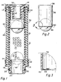
- Figure 1 is an elevational cross-sectional view of a fuel filter that employs the principles of this invention. All the elements of the filter are shown in cross-section except a tubular retention sleeve portion which is shown partially in exterior elevational view and partially broken away to reveal the cross-sectional configuration thereof. A ball member is shown in external elevational view, a substantial portion of the ball member being received within the lower portion of the retention sleeve.
- Figure 2 is an elevational view of the retention sleeve showing the ball, partially in dotted outline, as received within the sleeve.
- Figure 3 is an enlarged fragmentary view of the lower end of the retention sleeve showing the integral seat having a reduced internal diameter.
- the fuel filter in Figure 1 is of the fuel cartridge type, that is, the filter is of the type that is inserted into an opening in a housing. Therefore the filter of Figure 1 does not include a housing but is of the type which is received in a housing. Fuel to be filtered surrounds the filter element to pass through it and pass out of an opening in the housing (not seen).
- the filter element is formed of a rigid tubular fuel pervious core member 10 that can be made of metal, such as aluminum, or plastic. Core member 10 has a large number of openings therein through which fluid can freely pass.
- core member 10 is to form a structural base member to which the other elements of the filter are attached.
- Filter media 12 Surrounding core member 10 is a flexible filter media 12.
- Filter media 12 has two basic functions. The first is to intercept from the flow of fluid therethrough any particulate matter. Such particulate matter can be any solid substance such as dirt, sand, rust or any other physical element that could interfere with the flow of fuel in a mechanism, such as jet aircraft engines or the like.
- the second function of flexible filter media 12 is to intercept water.
- Other types of water absorbent flexible filter media are known and the type that is used in this invention may be any type which functions to permit the free passage of fuel therethrough but which intercepts particulate matter and water.
- Core member 10 has a first end 14 and a second end 16. Affixed at the second end 16 of the core member is a second end cap 18 that can be made of metal but is preferably of molded plastic. Second end cap 18 has a flow passageway 20 therethrough. The second end cap is further defined by an annular recess 22 that receives the lower end 16 of core member 10 and the lower end portion of the flexible filter media 12. The core member and flexible filter media are bonded to second end cap 18 by means of an adhesive bonding material.
- circumferential sealing surface 24 Formed at the upper end of second end cap 18 is a circumferential sealing surface 24.
- a circumferential external groove 26 receives an o-ring 28 so that the second end cap may be sealably plugged into a flow passageway opening (not shown) within the vessel (not shown) in which the filter is used.
- first end cap 30 Secured to the upper end 14 of core member 10 is a first end cap 30 that has a bored pressure port passageway 32 therethrough.
- the first end cap 30 has, as was described with reference to the second end cap, an annular recess 34 that sealably receives the upper end 14 of core member 10 and the upper end of flexible filter media 12.
- a tubular retention sleeve 36 Received within core member 10 at the upper end 14 is a tubular retention sleeve 36.
- This sleeve is preferably formed of thin deformable material such as metal or stiff plastic.
- Sleeve 36 has a first end 38 and a second end 40.
- Sleeve end 38 is secured within the upper end of core member 10.
- the first end 38 of tubular retention sleeve 36 is received within the annular recess 34 of first end cap 30.
- the tubular retention sleeve is in closed communication with the end cap - that is, the flow passageway 32 is in closed communication with the tubular retention sleeve 36.
- First end cap 30 has an internal circumferential surface 42 that forms a part of the annular recess 34.
- the upper portion of tubular retention sleeve 36 is bonded to the first end cap circumferential surface 42 so that tubular retention sleeve 36 is held in coaxial alignment with pressure port passageway 32.
- Tubular retention sleeve 36 is illustrated in Figures 2 and 3. As best seen in Figure 3, the tubular retention sleeve has an integral circumferential ball retention seat 44 of reduced internal diameter. As shown in Figures 1 and 2, a ball 46 is normally positioned within sleeve 38. Ball 46 is of an external diameter just slightly less than the internal diameter of sleeve 46 so that the ball fits snugly but slideably within the sleeve. Ball 46 is of external diameter slightly greater than the internal diameter of ball retention seat 44 so that ball 46 is normally held in sealed engagement with seat 44, the ball being held in such position by the pressure differential existing across the filter as fuel flows through flexible filter media 12 and into core member 10. The fuel normally flows freely out through the flow passageway 20 in the second end cap 18.
- the filter described herein has improved means of positive shutoff to close against further fluid flow when the filter has absorbed a quantity of water to thereby ensure that water does not pass into the fluid stream flowing through flow passageway 20.
Landscapes
- Chemical & Material Sciences (AREA)
- Chemical Kinetics & Catalysis (AREA)
- Physics & Mathematics (AREA)
- Thermal Sciences (AREA)
- Filtration Of Liquid (AREA)
Claims (8)
- Treibstoffilter mit einer verbesserten Einrichtung eines positiven Absperrorgans, das folgendes aufweist:ein unelastisches, röhrenförmiges, Treibstoff durchlässiges Kernelement (10) mit einem ersten Ende (14) und einem zweiten Ende (16);ein flexibles Filtermedium (12), welches das röhrenförmige Kernelement (10) umschließt, durch welches Treibstoff von außerhalb desselben in das röhrenförmige Kernelement (10) frei hindurchtritt, das aber dem Durchgang von partikelartiger Materie und Wasser widersteht;eine röhrenförmige Haltehülse (36), die innerhalb und in einer geschlossenen Verbindung mit dem röhrenförmigen Kernelement (10) an dem ersten Ende (14) desselben koaxial und vollständig aufgenommen ist, wobei die Haltehülse (36) ein erstes Ende (38) und ein zweites Ende (40) aufweist und an dem zweiten Hülsenende (40) einen einstückigen Kugelumfangs-Dichtungssitz (44) mit einem reduzierten Innendurchmesser besitzt;einen Abschlußdeckel (18), der an dem zweiten Ende (16) des röhrenförmigen Kernelements (10) befestigt ist, mit einer Öffnung (20), durch die eine verschlossene Verbindung mit dem zweiten Ende des röhrenförmigen Kernelements (16) besteht, und einer ringförmigen Verschlußfläche (24), welche die Öffnung dadurch umschließt, wobei die Verschlußfläche (24) als Dichtungssitz für eine Kugel (46) dienen kann; undeine Kugel (46) in dem Filter und normalerweise in der röhrenförmigen Haltehülse (36), die den Kugelumfangs-Dichtungssitz (44) verschließt, wenn Treibstoff durch das Filtermedium (12) in das röhrenförmige Kernelement (10) und durch den Abschlußdeckel (18) ausfließt,dadurch gekennzeichnet, daß die röhrenförmige Haltehülse (36) als längliche, dünnwandige, röhrenförmige Haltehülse geformt ist, die radial nach außen verformbar ist, um die Kugel (46) durch die Verschlußfläche (24) zu lassen, welche als Dichtungssitz für eine Kugel (46) dienen kann, wenn über das flexible Filtermedium (12) ein vorgegebener Druckabfall entsteht, um dadurch die Kugel (46) zu veranlassen, auf die ringförmige Verschlußfläche (24) des Abschlußdeckels (18) aufzusitzen und einen weiteren Durchfluß durch das Filter zu sperren.
- Treibstoffilter mit einer verbesserten Einrichtung eines positiven Absperrorgans nach Anspruch 1, dadurch gekennzeichnet, daß der Abschlußdeckel (18), der an dem zweiten Ende (16) des Kernelements (10) befestigt ist, ein zweiter Abschlußdeckel (18) ist, und daß das Filter außerdem folgendes umfaßt:einen ersten Abschlußdeckel (30) mit einem Druckanschluß-Durchlaß (32), der an dem ersten Ende (14) des röhrenförmigen Kernelements (10) befestigt ist.
- Treibstoffilter mit einer verbesserten Einrichtung eines positiven Absperrorgans nach Anspruch 2, dadurch gekennzeichnet, daß das erste Ende der Haltehülse (38) mit dem Druckanschluß-Durchlaß (32) an dem ersten Abschlußdeckel (30) koaxial befestigt ist.
- Treibstoffilter mit einer verbesserten Einrichtung eines positiven Absperrorgans nach Anspruch 1, 2 oder 3, dadurch gekennzeichnet, daß die Haltehülse (36) aus relativ dünnem, verformbarem Metall oder Plastikmaterial gebildet ist.
- Treibstoffilter mit einer verbesserten Einrichtung eines positiven Absperrorgans nach irgendeinem vorhergehenden Anspruch, dadurch gekennzeichnet, daß das flexible Filtermedium (12) dem Durchgang partikelartiger Materie widersteht.
- Treibstoffilter mit einer verbesserten Einrichtung eines positiven Absperrorgans nach irgendeinem der Ansprüche 1 bis 4, dadurch gekennzeichnet, daß das flexible Filtermedium (12) dem Durchgang von Wasser widersteht.
- Treibstoffilter mit einer verbesserten Einrichtung eines positiven Absperrorgans nach irgendeinem der Ansprüche 1 bis 4, dadurch gekennzeichnet, daß das flexible Filtermedium (12) dem Durchgang von sowohl partikelartiger Materie als auch Wasser widersteht.
- Treibstoffilter mit einer verbesserten Einrichtung eines positiven Absperrorgans nach irgendeinem vorhergehenden Anspruch, dadurch gekennzeichnet, daß der Innendurchmesser der röhrenförmigen Haltehülse (36) nur etwas größer als der Durchmesser der Kugel (46) ist, wobei die Kugel (46) eng anliegend, aber beweglich in die Haltehülse (36) paßt.
Priority Applications (3)
| Application Number | Priority Date | Filing Date | Title |
|---|---|---|---|
| US07/870,876 US5248414A (en) | 1992-04-20 | 1992-04-20 | Filter having improved means of positive shutoff incorporating sleeve valve seat |
| DE1993607298 DE69307298T2 (de) | 1993-04-28 | 1993-04-28 | Treibstoffilter mit einem positiven Absperrorgan |
| EP93303344A EP0622100B1 (de) | 1992-04-20 | 1993-04-28 | Treibstoffilter mit einem positiven Absperrorgan |
Applications Claiming Priority (2)
| Application Number | Priority Date | Filing Date | Title |
|---|---|---|---|
| US07/870,876 US5248414A (en) | 1992-04-20 | 1992-04-20 | Filter having improved means of positive shutoff incorporating sleeve valve seat |
| EP93303344A EP0622100B1 (de) | 1992-04-20 | 1993-04-28 | Treibstoffilter mit einem positiven Absperrorgan |
Publications (2)
| Publication Number | Publication Date |
|---|---|
| EP0622100A1 EP0622100A1 (de) | 1994-11-02 |
| EP0622100B1 true EP0622100B1 (de) | 1997-01-08 |
Family
ID=26134281
Family Applications (1)
| Application Number | Title | Priority Date | Filing Date |
|---|---|---|---|
| EP93303344A Expired - Lifetime EP0622100B1 (de) | 1992-04-20 | 1993-04-28 | Treibstoffilter mit einem positiven Absperrorgan |
Country Status (2)
| Country | Link |
|---|---|
| US (1) | US5248414A (de) |
| EP (1) | EP0622100B1 (de) |
Families Citing this family (4)
| Publication number | Priority date | Publication date | Assignee | Title |
|---|---|---|---|---|
| JP4870302B2 (ja) * | 1999-09-13 | 2012-02-08 | サザン・リサーチ・インスティテュート | 機械的全流フェールセーフ装置 |
| US9174075B2 (en) * | 2012-05-30 | 2015-11-03 | Nsip Holdings Llc | Explosion inhibiting portable fuel container and method of inhibiting explosions |
| US9790676B2 (en) | 2014-07-25 | 2017-10-17 | Innovative Devices Llc | Delayed shutoff device |
| CN114716048B (zh) * | 2022-05-18 | 2023-01-24 | 江苏明湖生物能源科技有限公司 | 一种污水处理清理用污水处理设备 |
Family Cites Families (9)
| Publication number | Priority date | Publication date | Assignee | Title |
|---|---|---|---|---|
| US3339734A (en) * | 1966-11-25 | 1967-09-05 | Bendix Corp | Frangible valve member for fuse filter |
| US3478881A (en) * | 1967-07-03 | 1969-11-18 | Bendix Corp | Shut-off valve for fuse filter |
| GB1227450A (de) * | 1967-07-03 | 1971-04-07 | ||
| US3766940A (en) * | 1971-08-25 | 1973-10-23 | Exxon Production Research Co | Pressure latching check valve |
| US4364825A (en) * | 1981-02-03 | 1982-12-21 | Wix Corporation | Liquid filter |
| US4485011A (en) * | 1981-12-30 | 1984-11-27 | Facet Enterprises, Inc. | Fuel contamination monitor with a shut off valve |
| US4787949A (en) * | 1986-06-30 | 1988-11-29 | Facet Automotive Filter Co. | Method of manufacturing highly water absorbent pleated filter laminate |
| US4992166A (en) * | 1988-06-13 | 1991-02-12 | Facet Enterprises, Inc. | Plastic fluid filter and method for manufacturing same |
| US4959141A (en) * | 1989-08-14 | 1990-09-25 | Facet Quantek, Inc. | Fuel filter with positive water shutoff |
-
1992
- 1992-04-20 US US07/870,876 patent/US5248414A/en not_active Expired - Fee Related
-
1993
- 1993-04-28 EP EP93303344A patent/EP0622100B1/de not_active Expired - Lifetime
Also Published As
| Publication number | Publication date |
|---|---|
| US5248414A (en) | 1993-09-28 |
| EP0622100A1 (de) | 1994-11-02 |
Similar Documents
| Publication | Publication Date | Title |
|---|---|---|
| EP0419030B1 (de) | Treibstoffilter mit einem Absperrorgan für Wasser | |
| US5458767A (en) | Fuel filter assembly with dual filter media and by-pass device | |
| US4082665A (en) | Fluid filter device for automotive power steering system | |
| US4657040A (en) | Bypass reverse flow valve | |
| US4485011A (en) | Fuel contamination monitor with a shut off valve | |
| US3368680A (en) | Filter with element subassembly | |
| US3557957A (en) | Filter assembly having a two-way bypass valve therein | |
| US5429663A (en) | Removal in aircraft of components from fluid mixtures | |
| US4145285A (en) | Fuel contamination monitor having a shut-off valve | |
| US5248414A (en) | Filter having improved means of positive shutoff incorporating sleeve valve seat | |
| US5160037A (en) | Filter assembly having by-pass system | |
| US3487930A (en) | Filter device with tubular guide means | |
| US3388800A (en) | Axial flow, compressible element, filter unit with bypass means | |
| EP0562079B1 (de) | Ueberdruckventil | |
| US20070034580A1 (en) | Fluid filter arrangement including valve arrangement and methods | |
| US6120683A (en) | Filter with shut-off valve | |
| GB2112295A (en) | A fuel filter with a shut off valve | |
| US5112478A (en) | Fuel filter for preventing water and particulate contamination | |
| CN112584913A (zh) | 过滤装置、过滤元件和适配件 | |
| US3442384A (en) | Combination filter and surge resistant bypass valve | |
| US3314541A (en) | Air purged filter device | |
| US20070181487A1 (en) | Fluid filter with bypass valve failure protection | |
| JPS6036326Y2 (ja) | 燃料フイルタ | |
| US4518493A (en) | Noise attenuating filter for fluid flow systems | |
| US20240307801A1 (en) | Filter element and filter system having radial flow bypass channels in the end plate |
Legal Events
| Date | Code | Title | Description |
|---|---|---|---|
| PUAI | Public reference made under article 153(3) epc to a published international application that has entered the european phase |
Free format text: ORIGINAL CODE: 0009012 |
|
| AK | Designated contracting states |
Kind code of ref document: A1 Designated state(s): DE ES FR GB IT NL |
|
| 17P | Request for examination filed |
Effective date: 19941210 |
|
| 17Q | First examination report despatched |
Effective date: 19950627 |
|
| GRAG | Despatch of communication of intention to grant |
Free format text: ORIGINAL CODE: EPIDOS AGRA |
|
| GRAH | Despatch of communication of intention to grant a patent |
Free format text: ORIGINAL CODE: EPIDOS IGRA |
|
| GRAH | Despatch of communication of intention to grant a patent |
Free format text: ORIGINAL CODE: EPIDOS IGRA |
|
| GRAA | (expected) grant |
Free format text: ORIGINAL CODE: 0009210 |
|
| AK | Designated contracting states |
Kind code of ref document: B1 Designated state(s): DE ES FR GB IT NL |
|
| PG25 | Lapsed in a contracting state [announced via postgrant information from national office to epo] |
Ref country code: NL Free format text: LAPSE BECAUSE OF FAILURE TO SUBMIT A TRANSLATION OF THE DESCRIPTION OR TO PAY THE FEE WITHIN THE PRESCRIBED TIME-LIMIT Effective date: 19970108 Ref country code: IT Free format text: LAPSE BECAUSE OF FAILURE TO SUBMIT A TRANSLATION OF THE DESCRIPTION OR TO PAY THE FEE WITHIN THE PRE;WARNING: LAPSES OF ITALIAN PATENTS WITH EFFECTIVE DATE BEFORE 2007 MAY HAVE OCCURRED AT ANY TIME BEFORE 2007. THE CORRECT EFFECTIVE DATE MAY BE DIFFERENT FROM THE ONE RECORDED.SCRIBED TIME-LIMIT Effective date: 19970108 Ref country code: FR Effective date: 19970108 Ref country code: ES Free format text: THE PATENT HAS BEEN ANNULLED BY A DECISION OF A NATIONAL AUTHORITY Effective date: 19970108 |
|
| REF | Corresponds to: |
Ref document number: 69307298 Country of ref document: DE Date of ref document: 19970220 |
|
| NLV1 | Nl: lapsed or annulled due to failure to fulfill the requirements of art. 29p and 29m of the patents act | ||
| EN | Fr: translation not filed | ||
| PLBE | No opposition filed within time limit |
Free format text: ORIGINAL CODE: 0009261 |
|
| STAA | Information on the status of an ep patent application or granted ep patent |
Free format text: STATUS: NO OPPOSITION FILED WITHIN TIME LIMIT |
|
| 26N | No opposition filed | ||
| REG | Reference to a national code |
Ref country code: GB Ref legal event code: IF02 |
|
| PGFP | Annual fee paid to national office [announced via postgrant information from national office to epo] |
Ref country code: GB Payment date: 20030423 Year of fee payment: 11 |
|
| PGFP | Annual fee paid to national office [announced via postgrant information from national office to epo] |
Ref country code: DE Payment date: 20030430 Year of fee payment: 11 |
|
| PG25 | Lapsed in a contracting state [announced via postgrant information from national office to epo] |
Ref country code: GB Free format text: LAPSE BECAUSE OF NON-PAYMENT OF DUE FEES Effective date: 20040428 |
|
| PG25 | Lapsed in a contracting state [announced via postgrant information from national office to epo] |
Ref country code: DE Free format text: LAPSE BECAUSE OF NON-PAYMENT OF DUE FEES Effective date: 20041103 |
|
| GBPC | Gb: european patent ceased through non-payment of renewal fee |
Effective date: 20040428 |