EP0622220A2 - Richtvorrichtung für Vielfach-Tintenstrahl-Kassetten beim Zweirichtungsdruck durch Abtasten eines Testmusters - Google Patents
Richtvorrichtung für Vielfach-Tintenstrahl-Kassetten beim Zweirichtungsdruck durch Abtasten eines Testmusters Download PDFInfo
- Publication number
- EP0622220A2 EP0622220A2 EP94106210A EP94106210A EP0622220A2 EP 0622220 A2 EP0622220 A2 EP 0622220A2 EP 94106210 A EP94106210 A EP 94106210A EP 94106210 A EP94106210 A EP 94106210A EP 0622220 A2 EP0622220 A2 EP 0622220A2
- Authority
- EP
- European Patent Office
- Prior art keywords
- axis
- inkjet
- carriage
- media
- test pattern
- Prior art date
- Legal status (The legal status is an assumption and is not a legal conclusion. Google has not performed a legal analysis and makes no representation as to the accuracy of the status listed.)
- Granted
Links
- 238000007639 printing Methods 0.000 title description 8
- 230000002457 bidirectional effect Effects 0.000 title description 3
- 238000012360 testing method Methods 0.000 claims abstract description 29
- 230000007246 mechanism Effects 0.000 claims abstract description 14
- 230000004044 response Effects 0.000 claims abstract description 9
- 230000001419 dependent effect Effects 0.000 claims abstract description 3
- 230000003287 optical effect Effects 0.000 claims description 14
- 239000000976 ink Substances 0.000 description 18
- 239000003086 colorant Substances 0.000 description 8
- 238000012937 correction Methods 0.000 description 8
- 238000000034 method Methods 0.000 description 7
- 230000003321 amplification Effects 0.000 description 6
- 230000000694 effects Effects 0.000 description 6
- 238000003199 nucleic acid amplification method Methods 0.000 description 6
- 230000004913 activation Effects 0.000 description 5
- 238000001914 filtration Methods 0.000 description 5
- 238000004364 calculation method Methods 0.000 description 4
- 238000010586 diagram Methods 0.000 description 4
- 238000012986 modification Methods 0.000 description 3
- 230000004048 modification Effects 0.000 description 3
- 238000012545 processing Methods 0.000 description 3
- 238000013459 approach Methods 0.000 description 2
- 238000006073 displacement reaction Methods 0.000 description 2
- 239000000463 material Substances 0.000 description 2
- 230000000717 retained effect Effects 0.000 description 2
- 239000002131 composite material Substances 0.000 description 1
- 238000013461 design Methods 0.000 description 1
- 238000005516 engineering process Methods 0.000 description 1
- 238000007641 inkjet printing Methods 0.000 description 1
- 238000004519 manufacturing process Methods 0.000 description 1
- 239000011159 matrix material Substances 0.000 description 1
- 239000007921 spray Substances 0.000 description 1
- 238000012795 verification Methods 0.000 description 1
Images


Classifications
-
- B—PERFORMING OPERATIONS; TRANSPORTING
- B41—PRINTING; LINING MACHINES; TYPEWRITERS; STAMPS
- B41J—TYPEWRITERS; SELECTIVE PRINTING MECHANISMS, i.e. MECHANISMS PRINTING OTHERWISE THAN FROM A FORME; CORRECTION OF TYPOGRAPHICAL ERRORS
- B41J2/00—Typewriters or selective printing mechanisms characterised by the printing or marking process for which they are designed
- B41J2/005—Typewriters or selective printing mechanisms characterised by the printing or marking process for which they are designed characterised by bringing liquid or particles selectively into contact with a printing material
- B41J2/01—Ink jet
- B41J2/015—Ink jet characterised by the jet generation process
- B41J2/04—Ink jet characterised by the jet generation process generating single droplets or particles on demand
- B41J2/045—Ink jet characterised by the jet generation process generating single droplets or particles on demand by pressure, e.g. electromechanical transducers
- B41J2/04501—Control methods or devices therefor, e.g. driver circuits, control circuits
- B41J2/04505—Control methods or devices therefor, e.g. driver circuits, control circuits aiming at correcting alignment
-
- B—PERFORMING OPERATIONS; TRANSPORTING
- B41—PRINTING; LINING MACHINES; TYPEWRITERS; STAMPS
- B41J—TYPEWRITERS; SELECTIVE PRINTING MECHANISMS, i.e. MECHANISMS PRINTING OTHERWISE THAN FROM A FORME; CORRECTION OF TYPOGRAPHICAL ERRORS
- B41J11/00—Devices or arrangements of selective printing mechanisms, e.g. ink-jet printers or thermal printers, for supporting or handling copy material in sheet or web form
- B41J11/36—Blanking or long feeds; Feeding to a particular line, e.g. by rotation of platen or feed roller
- B41J11/42—Controlling printing material conveyance for accurate alignment of the printing material with the printhead; Print registering
- B41J11/46—Controlling printing material conveyance for accurate alignment of the printing material with the printhead; Print registering by marks or formations on the paper being fed
-
- B—PERFORMING OPERATIONS; TRANSPORTING
- B41—PRINTING; LINING MACHINES; TYPEWRITERS; STAMPS
- B41J—TYPEWRITERS; SELECTIVE PRINTING MECHANISMS, i.e. MECHANISMS PRINTING OTHERWISE THAN FROM A FORME; CORRECTION OF TYPOGRAPHICAL ERRORS
- B41J2/00—Typewriters or selective printing mechanisms characterised by the printing or marking process for which they are designed
- B41J2/005—Typewriters or selective printing mechanisms characterised by the printing or marking process for which they are designed characterised by bringing liquid or particles selectively into contact with a printing material
- B41J2/01—Ink jet
- B41J2/015—Ink jet characterised by the jet generation process
- B41J2/04—Ink jet characterised by the jet generation process generating single droplets or particles on demand
- B41J2/045—Ink jet characterised by the jet generation process generating single droplets or particles on demand by pressure, e.g. electromechanical transducers
- B41J2/04501—Control methods or devices therefor, e.g. driver circuits, control circuits
- B41J2/04586—Control methods or devices therefor, e.g. driver circuits, control circuits controlling heads of a type not covered by groups B41J2/04575 - B41J2/04585, or of an undefined type
-
- B—PERFORMING OPERATIONS; TRANSPORTING
- B41—PRINTING; LINING MACHINES; TYPEWRITERS; STAMPS
- B41J—TYPEWRITERS; SELECTIVE PRINTING MECHANISMS, i.e. MECHANISMS PRINTING OTHERWISE THAN FROM A FORME; CORRECTION OF TYPOGRAPHICAL ERRORS
- B41J2/00—Typewriters or selective printing mechanisms characterised by the printing or marking process for which they are designed
- B41J2/005—Typewriters or selective printing mechanisms characterised by the printing or marking process for which they are designed characterised by bringing liquid or particles selectively into contact with a printing material
- B41J2/01—Ink jet
- B41J2/07—Ink jet characterised by jet control
-
- B—PERFORMING OPERATIONS; TRANSPORTING
- B41—PRINTING; LINING MACHINES; TYPEWRITERS; STAMPS
- B41J—TYPEWRITERS; SELECTIVE PRINTING MECHANISMS, i.e. MECHANISMS PRINTING OTHERWISE THAN FROM A FORME; CORRECTION OF TYPOGRAPHICAL ERRORS
- B41J19/00—Character- or line-spacing mechanisms
- B41J19/14—Character- or line-spacing mechanisms with means for effecting line or character spacing in either direction
- B41J19/142—Character- or line-spacing mechanisms with means for effecting line or character spacing in either direction with a reciprocating print head printing in both directions across the paper width
Definitions
- the present invention relates to printers and plotters. More specifically, the present invention relates to inkjet printers and plotters having multiple pens for multi-color operation.
- Inkjet printer/plotters such as those sold by Hewlett Packard Company, offer substantial improvements in speed over the conventional X-Y plotter.
- Inkjet printer/plotters typically include a pen having an array of nozzles. The pens are mounted on a carriage which is moved across the page in successive swaths.
- Each inkjet pen has heater circuits which, when activated, cause ink to be ejected from associated nozzles. As the pen is positioned over a given location, a jet of ink is ejected from the nozzle to provide a pixel of ink at a desired location.
- the mosaic of pixels thus created provides a desired composite image.
- a typical color inkjet printer/plotter has four inkjet pens, one that stores black ink, and three that store colored inks, e.g., magenta, cyan and yellow. The colors from the three color pens are mixed to obtain any particular color.
- the pens are typically mounted in stalls within an assembly which is mounted on the carriage of the printer/plotter.
- the carriage assembly positions the inkjet pens and typically holds the circuitry required for interface to the heater circuits in the inkjet pens.
- the need in the art is addressed by the present invention which provides a system for correcting for a time of flight delay of a drop of ink from an inkjet printhead.
- the inventive system includes a first mechanism for scanning the printhead along a first axis at a first velocity.
- a control circuit responsive to inkjet timing signals, causes the printhead to eject ink onto a media to create a test pattern thereon as the printhead is scanned along the first axis.
- a sensor optically sense the test pattern and provides a time of flight dependent phase signal in response thereto. This signal is processed to provide time of flight delay corrected inkjet timing signals for the first velocity in response to the phase signal.
- the processor is adapted to add an additional delay to the corrected timing signals to correct for curvature.
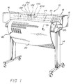
- Fig. 1 is a perspective view of a thermal inkjet large format printer/plotter incorporating the teachings of the present invention.
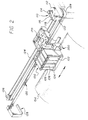
- Fig. 2 is a perspective view of the carriage assembly, the carriage positioning mechanism, and the paper positioning mechanism of the inventive printer/plotter.
- Fig. 3 is perspective view of a simplified representation of a media positioning system utilized in the inventive printer.
- Fig. 4 is a right-bottom perspective view of the carriage assembly of the present invention showing the sensor module.
- Fig. 5 is a magnified view of the test pattern utilized to effect pen alignment in accordance with the present teachings.
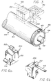
- Fig. 6a is a right-front perspective view of the sensor module utilized in the system of the present invention.
- Fig. 6b is a right-rear perspective view of the sensor module utilized in the system of the present invention.
- Fig. 6c shows a right-rear perspective view of the sensor module partially disassembled to reveal an outer housing and an inner assembly.
- Fig. 6d is a right-rear perspective view of the inner assembly of the sensor module of the present invention partially disassembled.
- Fig. 6e is a right-rear perspective view of the optical component holder of the sensor module of the present invention disassembled.
- Fig. 7 is a schematic diagram of the optical components of the sensor module of the present invention.
- Fig. 8a is a top view of the phase plate of the sensor module of the present invention.
- Fig. 8b is illustrative of the carriage axis patterns of the test pattern utilized in alignment system of the present invention.
- Fig. 8c is illustrative of the media axis patterns of the test pattern utilized in alignment system of the present invention.
- Fig. 9 shows a frontal representation of first, second, third and fourth inkjet cartridges positioned over media for movement along the carriage scan axis.
- Fig. 10 is a block diagram of the electronic circuit utilized in the alignment system of the present invention.
- Fig. 11 is a graph illustrative of the outputs of the carriage and media position encoders.
- Fig. 12 illustrates the sample pulses generated by the sample pulse generator circuit of the present invention.
- Fig. 13 illustrates the output of the sensor module of the present invention.
- Fig. 14 shows how the output of the sensor module of the present invention appears after amplification and filtering.
- Fig. 15 is a graph which illustrates how the output of the amplification and filtering circuit is sampled to provide data which is input to the slave microprocessor controller of the invention.
- Fig. 16 is a magnified bottom view of the thermal inkjet nozzles of each of the pen cartridges.
- Fig. 17 shows offsets due to speed and the effect of platen curvature for a print image.
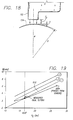
- Fig. 18 is a magnified side view of a nozzle above a curved platen.
- Fig. 19 is a graph of print image delay (B) versus carriage speed for the illustrative thermal inkjet printer of the present invention.
- Fig. 1 is a perspective view of a thermal inkjet large format printer/plotter incorporating the teachings of the present invention.
- the printer 10 includes a housing 12 mounted on a stand 14. The housing has left and right drive mechanism enclosures 16 and 18. A control panel 20 is mounted on the right enclosure 18.
- a carriage assembly 100 illustrated in phantom under a transparent cover 22, is adapted for reciprocal motion along a carriage bar 24, also shown in phantom.
- the position of the carriage assembly 100 in a horizontal or carriage scan axis is determined by a carriage positioning mechanism 110 (not shown) with respect to an encoder strip 120 (not shown) as discussed more fully below.
- a print medium 30 such as paper is positioned along a vertical or media axis by a media axis drive mechanism (not shown).
- the media axis is denoted as the 'x' axis and the scan axis is denoted as the 'y' axis.
- Fig. 2 is a perspective view of the carriage assembly 100, the carriage positioning mechanism 110 and the encoder strip 120.
- the carriage positioning mechanism 110 includes a carriage position motor 112 which has a shaft 114 extending therefrom through which the motor drives a small belt 116. Through the small belt 116, the carriage position motor 112 drives an idler 122 via the shaft 118 thereof. In turn, the idler 122 drives a belt 124 which is secured by a second idler 126.
- the belt 124 is attached to the carriage 100 and adapted is denoted as the 'y' axis.
- Fig. 2 is a perspective view of the carriage assembly 100, the carriage positioning mechanism 110 and the encoder strip 120.
- the carriage positioning mechanism 110 includes a carriage position motor 112 which has a shaft 114 extending therefrom through which the motor drives a small belt 116. Through the small belt 116, the carriage position motor 112 drives an idler 122 via the shaft 118 thereof. In turn, the idler 122 drives a belt 124 which is secured by a second idler 126.
- the belt 124 is attached to the carriage 100 and adapted to slide therethrough.
- the position of the carriage assembly in the scan axis is determined precisely by the use of the code strip 120.
- the code strip 120 is secured by a first stanchion 128 on one end and a second stanchion 129 on the other end.
- the code strip 120 may be implemented in the manner disclosed in EP-A-0 544 409, filed by the same applicant as the present application.
- an optical reader (not shown) is disposed on the carriage assembly and provides carriage position signals which are utilized by the invention to achieve optimal image registration in the manner described below.
- Fig. 3 is perspective view of a simplified representation of a media positioning system 150 utilized in the inventive printer.
- the media positioning system 150 includes a motor 152 which is coaxial with a media roller 154.
- the position of the media roller 154 is determined by a media position encoder 156.
- the media position encoder includes a disc 158 having a plurality of apertures 159 therein.
- An optical reader 160 provides a plurality of output pulses which facilitate the interchangeably herein as is common in the art.
- the printer 10 has four inkjet pens, 102, 104, 106, and 108 that store ink of different colors, e.g., black, yellow, magenta and cyan ink, respectively.
- inkjet pens 102, 104, 106, and 108 that store ink of different colors, e.g., black, yellow, magenta and cyan ink, respectively.
- selected nozzles in the thermal inkjet cartridge pens 102, 104, 106, and 108 are activated and ink is applied to the medium 30.
- the colors from the three color inkjet pens are mixed to obtain any other particular color.
- Fig. 4 is a right-bottom perspective view of the carriage assembly 100 of the present invention showing the sensor module 200.
- the carriage assembly 100 positions the inkjet pens and holds the circuitry required for interface to the heater circuits in the inkjet pens.
- the carriage assembly 100 includes a carriage 101 adapted for reciprocal motion on a front slider 103 and a rear slider 105.
- a first pen cartridge 102 is mounted in a first stall of the carriage 101. Note that the ink jet nozzles 107 of each pen are in line with the sensor module 200.
- test pattern 40 is generated whenever any of the cartridges are disturbed by activation of selected nozzles in selected pens.
- the test pattern is depicted in the magnified view of Fig. 5. The manner by which the test pattern 40 is generated and utilized to effect accurate image registration is discussed more fully below.
- an optical sensor module 200 is mounted on the carriage assembly 200.
- Optical sensors are known in the art. See for example, U. S. Patent No. 5,170,047 entitled Optical Sensor for Plotter Pen Verification, issued December 8, 1992 to Beauchamp et al., the teachings of which are incorporated herein by reference.
- the sensor module 200 optically senses the test pattern and provides electrical signals to the processor on the circuit board 170 indicative of the registration of the images thereon.
- Fig. 6a is a right-front perspective view of the sensor module 200 utilized in the system of the present invention.
- the sensor module 200 includes an outer housing 210 with two protrusions 212 and 214 adapted to receive first and second mounting screws.
- the outer housing 210 provides electrostatic discharge (ESD) protection for the module 200.
- ESD electrostatic discharge
- Fig. 6b is a right-rear perspective view of the sensor module 200.
- Fig. 6c shows a right-rear perspective view of the sensor module partially disassembled to reveal the outer housing 210 and an inner assembly 220.
- the inner assembly 220 is adapted to be retained within the outer housing 210.
- a flexible circuit 216 is disposed on the inner housing 220.
- the flexible circuit 216 includes an amplifier and contacts for interfacing the sensor module to the processor circuit as discussed more fully below.
- Fig. 6d is a right-rear perspective view of the inner assembly 220 of the sensor module 200 of the present invention partially disassembled. As illustrated in Fig. 6d, the inner assembly includes an optical component holder 222 and a cover 224.
- Fig. 6e is a right-rear perspective view of the optical component holder of the sensor module of the present invention disassembled.
- the optical component holder 222 is adapted to hold first and second lenses 226 and 228 in a fixed position relative to a phase plate 230.
- first and second light emitting diodes (LEDs) 232 and 234 are mounted on the flexible circuit 240 along with a photodetector 240 and amplifier and other circuit elements (not shown).
- the light emitting diodes and the photodetector are of conventional design and have a bandwidth which encompasses the frequencies of the colors of the inks provided by the pens 102 - 108 (even numbers only).
- the LEDs 232 and 234 are retained at an angle by first and second apertures 236 and 238, respectively, in the cover 224 of the holder 222.
- the cover 224 is secured to the holder 222 by first and second screws 231 and 233 which extend through first and second apertures 235 and 236, respectively, in the cover 224 and which are received by threads (not shown) in the holder 222.
- the functional relationships of the components of the sensor module are illustrated in the schematic diagram of Fig. 7.
- Light energy from the LEDs 232 and 234 impinges upon the test pattern 40 on the media 30 and is reflected to the photodetector 240 via the first and second lenses 226 and 228, respectively, and the phase plate 230.
- the lenses 226 and 228 focus energy on photodetector 240 via the phase plate 230.
- the phase plate 230 is a symmetrical grating constructed of plastic or other suitably opaque material.
- Fig. 8a is a top view of the phase plate 230.
- a symmetrical array of transparent openings 242 are provided in the opaque material.
- the line widths in the test pattern 40 for the carriage axis patterns 404 and 406 of Fig. 5 are equal to the horizontal spacings between the transparent openings 242 in the phase plate 230.
- the line widths in the test pattern 40 in the media axis patterns 408 of Fig. 5 are equal to the vertical spacings between the transparent openings 242 in the phase plate 230.
- the use of the phase plate 230 permits a simple, inexpensive optical arrangement to be used to quickly scan the pattern in each direction of movement.
- an output signal is provided which varies as a sine wave.
- the circuitry of the present invention stores these signals and examines the phase relationships thereof to determine the alignment of the pens for each direction of movement. The alignment procedure of the present invention by which the system corrects for carriage axis misalignment, paper axis misalignment and offsets due to speed and curvature will now be disclosed.
- the test pattern 40 of Fig. 5 is generated.
- the first pattern 402 is generated in the scan axis for the purpose of exercising the pens 102 - 108 (even numbers only).
- the first pattern 402 includes one segment for each cartridge utilized. For example, the first segment 410 is yellow, the second segment 412 is cyan, the third segment 416 is magenta and the fourth segment 418 is black.
- the second, third and fourth patterns 404, 406 and 408, respectively, are generated.
- the second pattern 404 is used to test for pen offsets due to speed and curvature.
- the third pattern 406 is used to test for misalignments in the carriage scan axis.
- the fourth patterns 408 are used to test for misalignments in the media axis.
- the invention is best understood with reference to the carriage and media scan axis alignment techniques thereof.
- the carriage scan axis alignment pattern 406 is generated by causing each pen to print a plurality of horizontally spaced vertical bars. As mentioned above, the thickness of the bars is equal to the spacing therebetween which is also equal to the width of the transparent openings in the phase plate 230 and the spacings therebetween.
- Fig. 9 shows a frontal representation of the first, second, third and fourth inkjet cartridges 102, 104, 106 and 108 positioned a height 'h' over the media 30 for movement along the carriage scan axis.
- the distances D12, D23, and D34 between the cartridges vary because of the mechanical tolerances and imperfections in the manufacturing of the device. This results in undesired displacements in the placement of the ink drops of one cartridge with respect to another cartridge.
- Pen misalignments in the carriage scan axis are corrected by scanning the third pattern 406 along the carriage scan axis with the sensor module 200.
- the sensors 226 and 228 thereof focus an image on the phase plate 230 and the photodetector 240.
- the photodetector 240 generates a sinusoidal output signal which is the mathematical convolution of the phase plate pattern and the test pattern 406.
- Fig. 10 is a block diagram of the electronic circuit 300 utilized in the alignment system of the present invention.
- the circuit 300 includes an amplification and filtering circuit 302, an analog to digital converter 304, a slave microprocessor controller 306, a sample pulse generator circuit 308, a carriage position encoder 310, a media position encoder 312, a master control and data processing unit 314, a carriage and media axis servo-control mechanism 316, a digital to analog converter 318 and a light control circuit 320.
- the electrical signals from the sensor module 200 are amplified, filtered and sampled by the slave microprocessor 306.
- the carriage position encoder 310 provides sample pulses as the carriage assembly 100 moves along the encoder strip 120 of Figs. 1 and 2.
- a sample pulse generator circuit 308 selects pulses from the carriage position encoder 310 or the media position encoder 312 depending on the test being performed.
- Fig. 11 is a graph illustrative of the quadrature outputs of the carriage and media position encoders.
- Fig. 12 illustrates the sample pulses generated by the sample pulse generator circuit 308.
- the slave microprocessor 306 uses the sample pulses to generate sample control signals for the analog-to-digital converter 304.
- the analog-to-digital converter 304 samples the output of the amplification and filter circuit 302.
- Figs. 13, 14 and 15. The output of the sensor module 200 is illustrated in Fig. 13.
- Fig. 14 shows how the output of the sensor module 200 appears after amplification and filtering.
- Fig. 15 is a graph which illustrates how the output of the amplification and filtering circuit 302 is sampled to provide data which is input to the slave microprocessor controller 306.
- the digitized samples are stored in memory for each direction of movement in the slave microprocessor controller 306.
- the master control and data processing unit 314 mathematically fits a reference sine wave to the sample points stored in memory, using a least squares fit algorithm or other suitable conventional algorithm, and computes a phase difference between the reference sine wave and the sensed sine wave. The location of the phase difference provides an indication as to which cartridge is out of alignment.
- the polarity of the phase difference indicates the direction of misalignment and the magnitude of the phase difference indicates the magnitude of the misalignment.
- Offsets for each cartridge are generated by the master control and data processing unit which are stored in the machine. These offsets are used to control activation of the pens as the assembly is scanned in the carriage axis via the servo mechanisms 316.
- Sensor module light activation is provided by the slave microprocessor controller 306, a digital-to-analog converter 318 and a light control circuit 320.
- Fig. 16 is a magnified bottom view of the thermal inkjet nozzles of each of the pen cartridges 102, 104, 106 and 108, respectively.
- Typically, only 96 of the 104 nozzles e.g., nozzles numbered 5 - 100 are used for printing. The remaining eight nozzles are used for offset adjustment as discussed more fully below.
- Fig. 17 shows offsets due to speed and the effect of platen curvature for a print image. At a higher speed V2, a greater offset from ideal results.
- a height differential ⁇ as illustrated in Fig. 18, exists.
- Fig. 18 is a magnified side view of a nozzle 102 above a curved platen 154.
- the variation in height due to curvature of the platen increases the delay time for the ink to reach the media. This manifests as curvature in the line as illustrated at (d) in Fig. 17 where the dashed line represents the ideal image shape and location.
- the present invention corrects for offsets due to speed and curvature as discussed below. Offsets due to speed are corrected first by printing images from a single cartridge (e.g., the black cartridge 102) at three different speeds in a each direction. This is illustrated at 430 - 440 (even numbers only) in the bidirectional pattern 404 of the test pattern 40 of Fig. 5.
- the bidirectional pattern 404 is generated by causing each pen to print a plurality of horizontally spaced vertical bars. As mentioned above, the thickness of the bars is equal to the spacing therebetween which is also equal to the width of the transparent openings in the phase plate 230 and the spacings therebetween.
- the first section 430 is printed at the lowest speed, e.g., 13.33 inches per second (ips) from right to left.
- the second section 432 is printed at the same speed from left to right.
- the third section 432 is printed at the next highest speed (16.67 ips) from right to left and the fourth section 436 is printed from left to right at the same speed.
- the fourth section 438 is printed from right to left and then the sixth section 440 is printed from left to right at the that speed.
- the pattern 404 is scanned and a phase for each section is determined in the manner described above.
- the measured phase difference between sections allows for a correction due to speed as illustrated in Fig. 17(e).
- correction for paper or media slippage is effected by first printing the media axis test pattern 408 of the test pattern 40 of Fig. 5.
- the pattern 408 includes five columns of vertically spaced horizontal bars 1 - 5.
- Each column has three rows segments 1 - 3.
- the first row in each column is created by scanning the carriage assembly 100 in the carriage axis and causing one cartridge (e.g., the cartridge containing cyan ink) to print.
- each column has a first row of cyan colored bars.
- a different colored cartridge is activated in each column with the exception that the cyan cartridge 108 is activated in the second row of the first and fifth columns.
- the cyan cartridge is activated for the third row of each column in the pattern 408.
- Media axis pen alignment is effected by scanning the pattern 408 with the sensor module 200 along the media axis, column by column and calculating phase data P ij , in the manner described above, where i denotes the row and j denotes the column.
- P m/c (P22 - P12) - 1/2(P32 - P12) [3]
- P y/c (P23 - P13) - 1/2(P33 - P13) [4]
- P k/c (P24 - P14) - 1/2(P34 - P14) [5]
- P m/c represents pen offset in the media axis between the cyan pen 108 and the magenta pen 106
- P y/c represents pen offset in the media axis between the cyan pen 108 and the yellow pen 104
- P k/c represents pen offset in the media axis between the cyan pen 108 and the black pen 102.
- the pen offsets in the media axis between pens are corrected by selecting certain nozzles for activation.
- nozzles 5 through 100 may be activated for all pens.
- This selective nozzle activation scheme has the effect of offsetting the images produced by the pen in the media axis.
Landscapes
- Ink Jet (AREA)
- Particle Formation And Scattering Control In Inkjet Printers (AREA)
- Accessory Devices And Overall Control Thereof (AREA)
- Character Spaces And Line Spaces In Printers (AREA)
Applications Claiming Priority (2)
| Application Number | Priority Date | Filing Date | Title |
|---|---|---|---|
| US08/055,619 US5448269A (en) | 1993-04-30 | 1993-04-30 | Multiple inkjet cartridge alignment for bidirectional printing by scanning a reference pattern |
| US55619 | 1993-04-30 |
Publications (3)
| Publication Number | Publication Date |
|---|---|
| EP0622220A2 true EP0622220A2 (de) | 1994-11-02 |
| EP0622220A3 EP0622220A3 (de) | 1995-05-03 |
| EP0622220B1 EP0622220B1 (de) | 1998-01-21 |
Family
ID=21999064
Family Applications (1)
| Application Number | Title | Priority Date | Filing Date |
|---|---|---|---|
| EP94106210A Expired - Lifetime EP0622220B1 (de) | 1993-04-30 | 1994-04-21 | Richtvorrichtung für Vielfach-Tintenstrahl-Kassetten beim Zweirichtungsdruck durch Abtasten eines Testmusters |
Country Status (5)
| Country | Link |
|---|---|
| US (1) | US5448269A (de) |
| EP (1) | EP0622220B1 (de) |
| JP (2) | JP3483614B2 (de) |
| DE (1) | DE69408020T2 (de) |
| ES (1) | ES2111198T3 (de) |
Cited By (13)
| Publication number | Priority date | Publication date | Assignee | Title |
|---|---|---|---|---|
| EP0863012A1 (de) * | 1997-03-04 | 1998-09-09 | Hewlett-Packard Company | Erfassung von Strahldüsenfehlern durch optisches Abtasten eines Probemusters |
| EP0867298A3 (de) * | 1997-03-28 | 1998-11-18 | Canon Kabushiki Kaisha | Drucker und Kontrollmusterdruckverfahren |
| EP0908320A1 (de) * | 1997-10-10 | 1999-04-14 | Lexmark International, Inc. | Kompensierung von versetzten Bildpunkten für einen Tintenstrahldrucker |
| EP0849702A3 (de) * | 1996-12-18 | 1999-06-30 | Canon Kabushiki Kaisha | Aufzeichnungskopf, Aufzeichnungsgerät, Aufzeichnungsverfahren und Aufzeichnungskassette, die den Aufzeichnungskopf verwendet |
| EP0990531A1 (de) * | 1998-09-28 | 2000-04-05 | Hewlett-Packard Company | Tintenstrahldrucker mit einer Einrichtung zur Kompensation der Flugzeitsvariation der Tintentröpfen |
| EP0895869A3 (de) * | 1997-07-31 | 2000-05-17 | Seiko Epson Corporation | Probemusterdruckverfahren und zugehörige Vorrichtung |
| EP1016524A3 (de) * | 1998-12-28 | 2000-11-22 | Canon Kabushiki Kaisha | Druckkopf, Druckvorrichtung und Ansteuerungsverfahren für einen Druckkopf |
| EP1179430A3 (de) * | 2000-08-09 | 2002-06-26 | Sony Corporation | Druckkopf, Verfahren zu dessen Herstellung und Drucker |
| US6607260B1 (en) * | 1998-12-21 | 2003-08-19 | Canon Kabushiki Kaisha | Recording apparatus and recording position correcting method |
| EP1451016A4 (de) * | 2001-10-05 | 2007-06-27 | Lexmark Int Inc | Verfahren zur ermittlung von druckkopffehlausrichtung eines druckers |
| EP1534527A4 (de) * | 2002-06-20 | 2007-11-07 | Lexmark Int Inc | Verfahren zur bestimmung der tintentropfengeschwindigkeit eines trägermontierten druckkopfs |
| EP3031610A1 (de) | 2014-12-08 | 2016-06-15 | Agfa Graphics Nv | Zuverlässiges Kalibrierverfahren für industrielle Tintenstrahlsysteme |
| CN107867072A (zh) * | 2016-09-28 | 2018-04-03 | 佳能株式会社 | 打印元件基板、打印头和打印设备 |
Families Citing this family (72)
| Publication number | Priority date | Publication date | Assignee | Title |
|---|---|---|---|---|
| US5825378A (en) * | 1993-04-30 | 1998-10-20 | Hewlett-Packard Company | Calibration of media advancement to avoid banding in a swath printer |
| ATE225540T1 (de) * | 1993-05-27 | 2002-10-15 | Canon Kk | Verfahren und vorrichtung zur tintenstrahlaufzeichnung |
| ES2116023T3 (es) * | 1995-09-08 | 1998-07-01 | Hewlett Packard Co | Metodo para hacer funcionar una impresora de chorro de tinta e impresora de chorro de tinta que emplea el metodo. |
| JP3254982B2 (ja) * | 1995-10-06 | 2002-02-12 | セイコーエプソン株式会社 | カラープリンタの印画位置調整方法及びカラープリンタ |
| US5847722A (en) * | 1995-11-21 | 1998-12-08 | Hewlett-Packard Company | Inkjet printhead alignment via measurement and entry |
| JPH09216350A (ja) * | 1996-02-09 | 1997-08-19 | Mutoh Ind Ltd | インクジェット出力装置 |
| KR0161821B1 (ko) * | 1996-06-20 | 1999-03-30 | 김광호 | 시리얼 프린터에서 양방향 인자 위치 자동 조절 장치 및 방법 |
| JP3521650B2 (ja) * | 1996-09-19 | 2004-04-19 | ブラザー工業株式会社 | 印字ヘッドの特性ランクを識別可能な印字装置 |
| US5835108A (en) * | 1996-09-25 | 1998-11-10 | Hewlett-Packard Company | Calibration technique for mis-directed inkjet printhead nozzles |
| KR100189084B1 (ko) * | 1996-10-16 | 1999-06-01 | 윤종용 | 수직 조정을 위한 패턴 인자 방법 |
| FR2755900B1 (fr) * | 1996-11-15 | 1999-01-29 | Toxot Sciences & Applic | Presse multicouleur a la continue par jet d'encre, procede de synchronisation d'une telle presse, et produit imprime obtenu a l'aide d'une telle presse |
| US5856833A (en) * | 1996-12-18 | 1999-01-05 | Hewlett-Packard Company | Optical sensor for ink jet printing system |
| JP3539108B2 (ja) * | 1997-02-04 | 2004-07-07 | セイコーエプソン株式会社 | 印刷品質調整方法並びに印刷方法及び装置 |
| US6154230A (en) * | 1997-02-06 | 2000-11-28 | Hewlett-Packard Company | Fractional dot column correction for better pen-to-pen alignment during printing |
| US5923344A (en) * | 1997-02-06 | 1999-07-13 | Hewlett-Packard Co. | Fractional dot column correction for scan axis alignment during printing |
| US6164749A (en) * | 1997-03-17 | 2000-12-26 | Hewlett-Packard Company | Method for user alignment of a color printer |
| US6386674B1 (en) * | 1997-10-28 | 2002-05-14 | Hewlett-Packard Company | Independent power supplies for color inkjet printers |
| JP3604891B2 (ja) * | 1997-12-24 | 2004-12-22 | キヤノン株式会社 | 補正方法及び記録装置 |
| JPH11240146A (ja) * | 1997-12-26 | 1999-09-07 | Canon Inc | 記録装置 |
| US6076915A (en) * | 1998-08-03 | 2000-06-20 | Hewlett-Packard Company | Inkjet printhead calibration |
| JP2000127360A (ja) * | 1998-10-23 | 2000-05-09 | Canon Inc | 記録装置および印字位置補正方法 |
| US6840597B1 (en) * | 1998-10-30 | 2005-01-11 | Hewlett-Packard Company | Color calibration in an inkjet printer |
| US6832824B1 (en) * | 1998-10-30 | 2004-12-21 | Hewlett-Packard Development Company, L.P. | Color-calibration sensor system for incremental printing |
| IL127317A0 (en) * | 1998-11-29 | 1999-09-22 | Ink Jet Technology | Printing mechanism for digital discs |
| US6450634B2 (en) * | 1999-01-29 | 2002-09-17 | Hewlett-Packard Company | Marking media using notches |
| US6234602B1 (en) | 1999-03-05 | 2001-05-22 | Hewlett-Packard Company | Automated ink-jet printhead alignment system |
| US6347856B1 (en) | 1999-03-05 | 2002-02-19 | Hewlett-Packard Company | Test pattern implementation for ink-jet printhead alignment |
| US6281908B1 (en) | 1999-04-15 | 2001-08-28 | Lexmark International, Inc. | Alignment system and method of compensating for skewed printing in an ink jet printer |
| US6322184B1 (en) | 1999-05-10 | 2001-11-27 | Hewlett-Packard Company | Method and apparatus for improved swath-to-swath alignment in an inkjet print engine device |
| US6352332B1 (en) | 1999-07-08 | 2002-03-05 | Hewlett-Packard Company | Method and apparatus for printing zone print media edge detection |
| US6428224B1 (en) | 1999-12-21 | 2002-08-06 | Lexmark International, Inc. | Error mapping technique for a printer |
| US6315383B1 (en) | 1999-12-22 | 2001-11-13 | Hewlett-Packard Company | Method and apparatus for ink-jet drop trajectory and alignment error detection and correction |
| JP2001253062A (ja) * | 2000-03-13 | 2001-09-18 | Canon Inc | 記録装置および記録方法 |
| US6357850B1 (en) * | 2000-07-18 | 2002-03-19 | Hewlett-Packard Company | Method for indicating accuracy of media advancement |
| US6450607B1 (en) | 2000-09-15 | 2002-09-17 | Lexmark International, Inc. | Alignment method for color ink jet printer |
| US6609781B2 (en) | 2000-12-13 | 2003-08-26 | Lexmark International, Inc. | Printer system with encoder filtering arrangement and method for high frequency error reduction |
| EP1238813A1 (de) | 2001-03-08 | 2002-09-11 | Agfa-Gevaert | Tintenstrahldrucker ausgerüstet zum Ausrichten von Druckköpfen |
| EP1238814B1 (de) | 2001-03-08 | 2003-12-03 | Agfa-Gevaert | Tintenstrahldrucker ausgestattet zum Ausrichten von Druckköpfe |
| US6454382B1 (en) * | 2001-05-11 | 2002-09-24 | Vladimir Galentovski | Malfunctioning nozzle detection apparatus |
| US6582049B2 (en) | 2001-05-31 | 2003-06-24 | Lexmark International, Inc. | Method and apparatus for detecting the position of an inkjet printhead |
| US6485124B1 (en) | 2001-07-02 | 2002-11-26 | Lexmark International, Inc. | Optical alignment method and detector |
| US6478401B1 (en) | 2001-07-06 | 2002-11-12 | Lexmark International, Inc. | Method for determining vertical misalignment between printer print heads |
| US6685297B2 (en) | 2001-09-24 | 2004-02-03 | Xerox Corporation | Print head alignment method, test pattern used in the method, and a system thereof |
| US20030058295A1 (en) * | 2001-09-26 | 2003-03-27 | Heiles Tod S. | Printing mechanism swath height and line-feed error compensation |
| US6533385B1 (en) * | 2001-12-14 | 2003-03-18 | Pitney Bowes Inc. | Method for determining a printer's signature and the number of dots per inch printed in a document to provide proof that the printer printed a particular document |
| US6612684B2 (en) | 2001-12-14 | 2003-09-02 | Pitney Bowes Inc. | Method for determining a printer's signature to provide proof that the printer printed a particular document |
| US6695426B2 (en) | 2002-02-11 | 2004-02-24 | Lexmark International, Inc. | Ink jet printer improved dot placement technique |
| US6964465B2 (en) * | 2002-02-21 | 2005-11-15 | Seiko Epson Corporation | Printing apparatus, storage medium having a program recorded thereon, pattern, computer system, and printing method |
| US6702419B2 (en) | 2002-05-03 | 2004-03-09 | Osram Opto Semiconductors Gmbh | System and method for delivering droplets |
| US6612680B1 (en) | 2002-06-28 | 2003-09-02 | Lexmark International, Inc. | Method of imaging substance depletion detection for an imaging device |
| US6883892B2 (en) * | 2002-10-31 | 2005-04-26 | Hewlett-Packard Development Company, L.P. | Printing apparatus calibration |
| KR100472491B1 (ko) * | 2003-05-10 | 2005-03-09 | 삼성전자주식회사 | 잉크젯 프린터의 화상 정렬방법 및 장치 |
| US6938975B2 (en) * | 2003-08-25 | 2005-09-06 | Lexmark International, Inc. | Method of reducing printing defects in an ink jet printer |
| KR100561412B1 (ko) * | 2003-12-24 | 2006-03-16 | 삼성전자주식회사 | 프린터의 헤드를 정렬하는 방법 및 그 장치 |
| US7708362B2 (en) * | 2004-04-21 | 2010-05-04 | Hewlett-Packard Development Company, L.P. | Printhead error compensation |
| US7380897B2 (en) * | 2005-06-06 | 2008-06-03 | Lexmark International, Inc. | Method and apparatus for calibrating a printhead |
| US7445302B2 (en) * | 2005-09-21 | 2008-11-04 | Lexmark International, Inc | Method for determining a printhead gap in an ink jet apparatus that performs bi-directional alignment of the printhead |
| JP2007098601A (ja) * | 2005-09-30 | 2007-04-19 | Seiko Epson Corp | 液体噴射装置及び記録装置 |
| US7556338B2 (en) * | 2005-11-28 | 2009-07-07 | Brother Kogyo Kabushiki Kaisha | Jetting timing determining method and liquid-droplet jetting method |
| DE102005060785A1 (de) * | 2005-12-16 | 2007-06-28 | Man Roland Druckmaschinen Ag | Verfahren zum Betreiben einer Inkjet-Druckeinrichtung |
| TWI288709B (en) * | 2006-07-19 | 2007-10-21 | Sunplus Technology Co Ltd | Method and system for automatically calibrating speed of carriage for an inkjet print head |
| CN100577431C (zh) * | 2006-09-05 | 2010-01-06 | 凌阳科技股份有限公司 | 可自动校正喷墨头承座速度不均匀的方法及系统 |
| US20090026265A1 (en) * | 2007-07-25 | 2009-01-29 | Grosse Jason C | Determining a position of a print carriage |
| JP2010000551A (ja) * | 2008-06-18 | 2010-01-07 | Universal Shipbuilding Corp | 鋼板印字装置 |
| US7891757B2 (en) * | 2008-09-30 | 2011-02-22 | Eastman Kodak Company | Marking element registration |
| US8197022B2 (en) * | 2009-09-29 | 2012-06-12 | Eastman Kodak Company | Automated time of flight speed compensation |
| US8702195B2 (en) | 2011-09-02 | 2014-04-22 | Hewlett-Packard Development Company, L.P. | Determining misalignment of a printhead in a printer |
| EP2626209B1 (de) * | 2012-02-12 | 2018-04-11 | Baumer Inspection GmbH | Verfahren und Vorrichtung zur Erkennung von Fehlfunktionen von Düsen eines Tintenstrahldruckers |
| US8991960B2 (en) * | 2012-08-24 | 2015-03-31 | Hewlett-Packard Development Company, L.P. | Compensation of bi-directional alignment error |
| US9566799B1 (en) * | 2015-10-14 | 2017-02-14 | Funai Electric Co., Ltd. (Jp) | Imaging apparatus and method for reducing banding |
| WO2020005316A1 (en) * | 2018-06-25 | 2020-01-02 | American Crafts, L.C. | Heat pen for use with electronic cutting and/or drawing systems |
| DE102020107294A1 (de) | 2020-03-17 | 2021-09-23 | Notion Systems GmbH | Verfahren zur Kalibrierung von Inkjet-Düsen in einer Druckvorrichtung und eine Druckvorrichtung zum Betrieb mit einem solchen Verfahren |
Family Cites Families (13)
| Publication number | Priority date | Publication date | Assignee | Title |
|---|---|---|---|---|
| JPS56144979A (en) * | 1980-04-15 | 1981-11-11 | Ricoh Co Ltd | Discrimination and control circuit for ink drop-adhered position |
| US4675696A (en) * | 1982-04-07 | 1987-06-23 | Canon Kabushiki Kaisha | Recording apparatus |
| JPS58173673A (ja) * | 1982-04-07 | 1983-10-12 | Canon Inc | 記録装置における記録ヘッドの位置ずれ補正のためのテストパターン記録方法 |
| US4524364A (en) * | 1982-11-22 | 1985-06-18 | Xerox Corporation | Circuitry for correcting dot placement for oscillating carriage ink jet printer |
| JPS59145159A (ja) * | 1983-02-09 | 1984-08-20 | Toppan Printing Co Ltd | インクジエツトプリンタ |
| US4808832A (en) * | 1986-09-11 | 1989-02-28 | Synergy Computer Graphics Corp. | Registration system for a moving substrate |
| JPH0729440B2 (ja) * | 1986-12-17 | 1995-04-05 | キヤノン株式会社 | インクジエツト記録装置 |
| JPH02122935A (ja) * | 1988-11-02 | 1990-05-10 | Canon Inc | インクジェット記録装置 |
| US4878063A (en) * | 1988-12-05 | 1989-10-31 | Eastman Kodak Company | Multicolor printing apparatus and method having vernier detection/correction system for adjusting color separation planes |
| US4922270A (en) * | 1989-01-31 | 1990-05-01 | Hewlett-Packard Company | Inter pen offset determination and compensation in multi-pen thermal ink jet pen printing systems |
| JPH04128052A (ja) * | 1990-09-19 | 1992-04-28 | Canon Inc | インクジェット記録装置 |
| US5170047A (en) * | 1991-09-20 | 1992-12-08 | Hewlett-Packard Company | Optical sensor for plotter pen verification |
| US5250956A (en) * | 1991-10-31 | 1993-10-05 | Hewlett-Packard Company | Print cartridge bidirectional alignment in carriage axis |
-
1993
- 1993-04-30 US US08/055,619 patent/US5448269A/en not_active Expired - Lifetime
-
1994
- 1994-04-18 JP JP10337394A patent/JP3483614B2/ja not_active Expired - Fee Related
- 1994-04-21 EP EP94106210A patent/EP0622220B1/de not_active Expired - Lifetime
- 1994-04-21 ES ES94106210T patent/ES2111198T3/es not_active Expired - Lifetime
- 1994-04-21 DE DE69408020T patent/DE69408020T2/de not_active Expired - Fee Related
-
2003
- 2003-07-30 JP JP2003282732A patent/JP2004001558A/ja active Pending
Cited By (22)
| Publication number | Priority date | Publication date | Assignee | Title |
|---|---|---|---|---|
| US6168251B1 (en) | 1996-12-18 | 2001-01-02 | Canon Kabushiki Kaisha | Recording apparatus and method for correcting offset of recorded pixels |
| EP0849702A3 (de) * | 1996-12-18 | 1999-06-30 | Canon Kabushiki Kaisha | Aufzeichnungskopf, Aufzeichnungsgerät, Aufzeichnungsverfahren und Aufzeichnungskassette, die den Aufzeichnungskopf verwendet |
| EP0863012A1 (de) * | 1997-03-04 | 1998-09-09 | Hewlett-Packard Company | Erfassung von Strahldüsenfehlern durch optisches Abtasten eines Probemusters |
| EP0867298A3 (de) * | 1997-03-28 | 1998-11-18 | Canon Kabushiki Kaisha | Drucker und Kontrollmusterdruckverfahren |
| US6084606A (en) * | 1997-03-28 | 2000-07-04 | Canon Kabushiki Kaisha | Printing apparatus and check pattern printing method |
| EP0895869A3 (de) * | 1997-07-31 | 2000-05-17 | Seiko Epson Corporation | Probemusterdruckverfahren und zugehörige Vorrichtung |
| US6310637B1 (en) | 1997-07-31 | 2001-10-30 | Seiko Epson Corporation | Method of printing test pattern and printing apparatus for the same |
| EP0908320A1 (de) * | 1997-10-10 | 1999-04-14 | Lexmark International, Inc. | Kompensierung von versetzten Bildpunkten für einen Tintenstrahldrucker |
| US6361137B1 (en) | 1998-09-28 | 2002-03-26 | Hewlett-Packard Company | Method and apparatus for compensating for variations in printhead-to-media spacing and printhead scanning velocity in an ink-jet hard copy apparatus |
| EP0990531A1 (de) * | 1998-09-28 | 2000-04-05 | Hewlett-Packard Company | Tintenstrahldrucker mit einer Einrichtung zur Kompensation der Flugzeitsvariation der Tintentröpfen |
| US6607260B1 (en) * | 1998-12-21 | 2003-08-19 | Canon Kabushiki Kaisha | Recording apparatus and recording position correcting method |
| EP1016524A3 (de) * | 1998-12-28 | 2000-11-22 | Canon Kabushiki Kaisha | Druckkopf, Druckvorrichtung und Ansteuerungsverfahren für einen Druckkopf |
| US6460976B1 (en) | 1998-12-28 | 2002-10-08 | Canon Kabushiki Kaisha | Printing apparatus having control means of controlling timing for driving blocks of print elements |
| EP1666256A1 (de) * | 2000-08-09 | 2006-06-07 | Sony Corporation | Druckkopf, Verfahren zu dessen Herstellung und Drucker |
| US6663223B2 (en) | 2000-08-09 | 2003-12-16 | Sony Corporation | Print head, manufacturing method therefor and printer |
| EP1179430A3 (de) * | 2000-08-09 | 2002-06-26 | Sony Corporation | Druckkopf, Verfahren zu dessen Herstellung und Drucker |
| SG136001A1 (en) * | 2000-08-09 | 2007-10-29 | Sony Corp | Print head, manufacturing method therefor, and printer |
| EP1451016A4 (de) * | 2001-10-05 | 2007-06-27 | Lexmark Int Inc | Verfahren zur ermittlung von druckkopffehlausrichtung eines druckers |
| EP1534527A4 (de) * | 2002-06-20 | 2007-11-07 | Lexmark Int Inc | Verfahren zur bestimmung der tintentropfengeschwindigkeit eines trägermontierten druckkopfs |
| EP3031610A1 (de) | 2014-12-08 | 2016-06-15 | Agfa Graphics Nv | Zuverlässiges Kalibrierverfahren für industrielle Tintenstrahlsysteme |
| CN107867072A (zh) * | 2016-09-28 | 2018-04-03 | 佳能株式会社 | 打印元件基板、打印头和打印设备 |
| CN107867072B (zh) * | 2016-09-28 | 2019-09-20 | 佳能株式会社 | 打印元件基板、打印头和打印设备 |
Also Published As
| Publication number | Publication date |
|---|---|
| EP0622220A3 (de) | 1995-05-03 |
| DE69408020D1 (de) | 1998-02-26 |
| JP3483614B2 (ja) | 2004-01-06 |
| DE69408020T2 (de) | 1998-05-07 |
| JP2004001558A (ja) | 2004-01-08 |
| ES2111198T3 (es) | 1998-03-01 |
| EP0622220B1 (de) | 1998-01-21 |
| JPH071726A (ja) | 1995-01-06 |
| US5448269A (en) | 1995-09-05 |
Similar Documents
| Publication | Publication Date | Title |
|---|---|---|
| EP0622220B1 (de) | Richtvorrichtung für Vielfach-Tintenstrahl-Kassetten beim Zweirichtungsdruck durch Abtasten eines Testmusters | |
| EP0622238B1 (de) | Tintenstrahldrucker mit Referenzmuster für das Abgleichen von Mehrfach-Tintenstrahlkassetten | |
| EP0622237B1 (de) | Phasenplattenentwurf für das Abgleichen durch Referenzmusterabtastung von Mehrfach-Farbstrahlkassetten | |
| EP0622239B1 (de) | Abgleichsystem für Mehrfach-Tintenstrahldruckpatronen | |
| US5796414A (en) | Systems and method for establishing positional accuracy in two dimensions based on a sensor scan in one dimension | |
| US5835108A (en) | Calibration technique for mis-directed inkjet printhead nozzles | |
| EP0978390B1 (de) | Tintenstrahldruckkopfkalibrierung | |
| EP1176802B1 (de) | Techniken zum Messen der Lage von Markierungen auf Medien und zum Ausrichten von Tintenstrahlgeräten | |
| US5109239A (en) | Inter pen offset determination and compensation in multi-pen ink jet printing systems | |
| US7775654B2 (en) | Printing apparatus, program, and printing method | |
| US4922270A (en) | Inter pen offset determination and compensation in multi-pen thermal ink jet pen printing systems | |
| EP0775587B1 (de) | Orientierung eines Tintenstrahldruckkopfes durch Fehlermessung und -Speichersystem | |
| US5036340A (en) | Piezoelectric detector for drop position determination in multi-pen ink jet printing systems | |
| EP0622236B1 (de) | Abgleichsystem für Mehrfach-Tintenstrahldruckpatronen | |
| US7891757B2 (en) | Marking element registration | |
| US20030016266A1 (en) | Linear position encoding system | |
| EP1281935B1 (de) | Linearpositionskodiersystem | |
| GB2349213A (en) | Determining the positional accuracy of multi-colour printing heads |
Legal Events
| Date | Code | Title | Description |
|---|---|---|---|
| PUAI | Public reference made under article 153(3) epc to a published international application that has entered the european phase |
Free format text: ORIGINAL CODE: 0009012 |
|
| AK | Designated contracting states |
Kind code of ref document: A2 Designated state(s): DE ES FR GB IT |
|
| PUAL | Search report despatched |
Free format text: ORIGINAL CODE: 0009013 |
|
| AK | Designated contracting states |
Kind code of ref document: A3 Designated state(s): DE ES FR GB IT |
|
| 17P | Request for examination filed |
Effective date: 19950415 |
|
| 17Q | First examination report despatched |
Effective date: 19960401 |
|
| GRAG | Despatch of communication of intention to grant |
Free format text: ORIGINAL CODE: EPIDOS AGRA |
|
| GRAG | Despatch of communication of intention to grant |
Free format text: ORIGINAL CODE: EPIDOS AGRA |
|
| GRAH | Despatch of communication of intention to grant a patent |
Free format text: ORIGINAL CODE: EPIDOS IGRA |
|
| GRAH | Despatch of communication of intention to grant a patent |
Free format text: ORIGINAL CODE: EPIDOS IGRA |
|
| GRAA | (expected) grant |
Free format text: ORIGINAL CODE: 0009210 |
|
| AK | Designated contracting states |
Kind code of ref document: B1 Designated state(s): DE ES FR GB IT |
|
| REF | Corresponds to: |
Ref document number: 69408020 Country of ref document: DE Date of ref document: 19980226 |
|
| REG | Reference to a national code |
Ref country code: ES Ref legal event code: FG2A Ref document number: 2111198 Country of ref document: ES Kind code of ref document: T3 |
|
| ET | Fr: translation filed | ||
| ITF | It: translation for a ep patent filed | ||
| PLBE | No opposition filed within time limit |
Free format text: ORIGINAL CODE: 0009261 |
|
| STAA | Information on the status of an ep patent application or granted ep patent |
Free format text: STATUS: NO OPPOSITION FILED WITHIN TIME LIMIT |
|
| 26N | No opposition filed | ||
| REG | Reference to a national code |
Ref country code: GB Ref legal event code: 732E |
|
| REG | Reference to a national code |
Ref country code: FR Ref legal event code: TP |
|
| REG | Reference to a national code |
Ref country code: GB Ref legal event code: IF02 |
|
| PGFP | Annual fee paid to national office [announced via postgrant information from national office to epo] |
Ref country code: IT Payment date: 20060430 Year of fee payment: 13 |
|
| PGFP | Annual fee paid to national office [announced via postgrant information from national office to epo] |
Ref country code: ES Payment date: 20070426 Year of fee payment: 14 |
|
| PGFP | Annual fee paid to national office [announced via postgrant information from national office to epo] |
Ref country code: DE Payment date: 20070531 Year of fee payment: 14 |
|
| PGFP | Annual fee paid to national office [announced via postgrant information from national office to epo] |
Ref country code: GB Payment date: 20070425 Year of fee payment: 14 |
|
| PGFP | Annual fee paid to national office [announced via postgrant information from national office to epo] |
Ref country code: FR Payment date: 20070417 Year of fee payment: 14 |
|
| GBPC | Gb: european patent ceased through non-payment of renewal fee |
Effective date: 20080421 |
|
| PG25 | Lapsed in a contracting state [announced via postgrant information from national office to epo] |
Ref country code: DE Free format text: LAPSE BECAUSE OF NON-PAYMENT OF DUE FEES Effective date: 20081101 |
|
| REG | Reference to a national code |
Ref country code: FR Ref legal event code: ST Effective date: 20081231 |
|
| PG25 | Lapsed in a contracting state [announced via postgrant information from national office to epo] |
Ref country code: FR Free format text: LAPSE BECAUSE OF NON-PAYMENT OF DUE FEES Effective date: 20080430 |
|
| REG | Reference to a national code |
Ref country code: ES Ref legal event code: FD2A Effective date: 20080422 |
|
| PG25 | Lapsed in a contracting state [announced via postgrant information from national office to epo] |
Ref country code: GB Free format text: LAPSE BECAUSE OF NON-PAYMENT OF DUE FEES Effective date: 20080421 |
|
| PG25 | Lapsed in a contracting state [announced via postgrant information from national office to epo] |
Ref country code: ES Free format text: LAPSE BECAUSE OF NON-PAYMENT OF DUE FEES Effective date: 20080422 |
|
| PG25 | Lapsed in a contracting state [announced via postgrant information from national office to epo] |
Ref country code: IT Free format text: LAPSE BECAUSE OF NON-PAYMENT OF DUE FEES Effective date: 20070421 |