EP0622496B1 - Verfahren zur Herstellung eines Mannloches - Google Patents
Verfahren zur Herstellung eines Mannloches Download PDFInfo
- Publication number
- EP0622496B1 EP0622496B1 EP19940400896 EP94400896A EP0622496B1 EP 0622496 B1 EP0622496 B1 EP 0622496B1 EP 19940400896 EP19940400896 EP 19940400896 EP 94400896 A EP94400896 A EP 94400896A EP 0622496 B1 EP0622496 B1 EP 0622496B1
- Authority
- EP
- European Patent Office
- Prior art keywords
- manufacture
- culvert
- axis
- central element
- peripheral
- Prior art date
- Legal status (The legal status is an assumption and is not a legal conclusion. Google has not performed a legal analysis and makes no representation as to the accuracy of the status listed.)
- Expired - Lifetime
Links
- 238000000034 method Methods 0.000 title claims description 15
- 230000002093 peripheral effect Effects 0.000 claims description 21
- 238000004519 manufacturing process Methods 0.000 claims description 13
- 238000005266 casting Methods 0.000 claims 3
- 238000005520 cutting process Methods 0.000 claims 2
- 238000007689 inspection Methods 0.000 claims 1
- 239000012530 fluid Substances 0.000 description 5
- 238000005553 drilling Methods 0.000 description 4
- 238000000465 moulding Methods 0.000 description 4
- XLYOFNOQVPJJNP-UHFFFAOYSA-N water Substances O XLYOFNOQVPJJNP-UHFFFAOYSA-N 0.000 description 3
- 238000010276 construction Methods 0.000 description 2
- 239000007788 liquid Substances 0.000 description 2
- 240000008042 Zea mays Species 0.000 description 1
- 230000006978 adaptation Effects 0.000 description 1
- 238000004026 adhesive bonding Methods 0.000 description 1
- 230000003628 erosive effect Effects 0.000 description 1
- 239000003673 groundwater Substances 0.000 description 1
- 238000003780 insertion Methods 0.000 description 1
- 230000037431 insertion Effects 0.000 description 1
- 238000012423 maintenance Methods 0.000 description 1
- 239000000463 material Substances 0.000 description 1
- 239000010865 sewage Substances 0.000 description 1
- 239000000126 substance Substances 0.000 description 1
Images
Classifications
-
- E—FIXED CONSTRUCTIONS
- E03—WATER SUPPLY; SEWERAGE
- E03F—SEWERS; CESSPOOLS
- E03F5/00—Sewerage structures
- E03F5/02—Manhole shafts or other inspection chambers; Snow-filling openings; accessories
-
- E—FIXED CONSTRUCTIONS
- E02—HYDRAULIC ENGINEERING; FOUNDATIONS; SOIL SHIFTING
- E02D—FOUNDATIONS; EXCAVATIONS; EMBANKMENTS; UNDERGROUND OR UNDERWATER STRUCTURES
- E02D29/00—Independent underground or underwater structures; Retaining walls
- E02D29/12—Manhole shafts; Other inspection or access chambers; Accessories therefor
Definitions
- the subject of the present invention is a method for manufacturing a concrete ditch, or concrete manhole bottom, arranged to connect at least two drain pipes, each of which axis is substantially horizontal.
- Cunettes are commonly used in sites to ensure the connection between at least two elements, generally tubular, of a flow network of fluid.
- the network can be connected to the sewer network; the fluid can be sewage or any other liquid possibly polluting.
- a cunette allows the visit and maintenance of the network by vision from above, and has lateral circular holes to receive network pipes.
- Most gutters are often made of concrete or similar.
- the connection between the pipes, and of course between each pipe and each cunette is watertight; likewise, the different joints between the viewing elements and the can be waterproof to avoid pollution of groundwater.
- the depth of the gaze must be adapted to the relative depth of the network in relation to to the water table.
- the pipes, or nozzles have diameters up to 300 mm and more, and there can be several pipes of different diameters arriving and departing from the same cunette.
- the object of the present invention is to provide a cunette whose manufacturing process is such that can receive pipes of different diameters with varying angles and levels of arrival and departure that it is adapted to demand according to the site and the network slope.
- the proposed cunette is modular in design, drilling the side holes of the central element is performed on demand in accordance at the desired angle and then we have the elements peripherals facing these orifices so that, on the construction site, the drain pipes always arrive perpendicular to the wall of the cunette which allows on the one hand to ensure a good seal between the pipe and the wall of the cunette on the other hand to avoid the presence of angled connecting piece.
- the drilling step of the central element with axis vertical is integrated in the molding step, with insertion a reservation in the veil of the vertical wall for the side holes.
- This technique is particularly adapted when we know in advance what will be angles formed between them by the pipes.
- the step of assembling the elements peripherals on the central element is carried out by bonding of each peripheral element to the central element, alternatively, mechanical fixing can also be provided.
- the cunette has a height variable between 300 and 2,500 mm. So the height variable of the cunette, adapted to the site, allows to have the joint between the cunette and the upper element of preferably above the level of the water table.
- each peripheral element with a horizontal axis can be adapted to the diameter of the pipe connected to it, even, the side openings are located at different heights which each correspond to the height of the axis of the drain hose to be connected; for this connection we can provide a male or female connector which can advantageously have a gasket.
- the bottom of the cunette is designed to reduce pressure losses and therefore to favor the flow of fluids.
- the material used to make this layout can be adapted to the chemical aggressiveness of the fluid (aluminous concrete %) or erosion caused by flow slope.
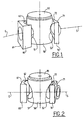
- FIG 1 an element central 50 and two peripheral elements 60, 70 in sight exploded and ready to be assembled.
- the central element 50 is a hollow cylinder with vertical axis and closed downwards, it is here provided with a cover 90 which is of course removable ; the vertical wall of the central element has two orifices 51, 52 which are arranged coaxial to future drain pipes whose axes E, S are shown; in Figure 1 only the orifice 51 is really visible.
- the two peripheral elements 60, 70 have essentially the shaped like a hollow cylinder opening on both sides between a planar face 61, 71 and a concave face 62, 72; each concave face 62, 72 has a curvature which matches the external face of the hollow cylinder of the central element 50 with a vertical axis.
- the peripheral elements 60, 70 are represented with a generally parallelepiped exterior shape but this is clearly not an obligation and their outer surface could just as well be in the form of a cylinder preferably coaxial with the axis of the drove.
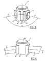
- Figure 2 shows the same elements as Figure 1, the same references have been kept, only the viewing angle is changed so that you can see better, on this figure 2, the concave surface 62 of the peripheral element 60 and also the orifice 52 of the central element 50.
- the axes E and S are substantially coaxial but this is obviously not an obligation since the holes 51, 52 are made on demand.
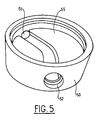
- Figure 3 is shown an assembled cunette 1 whose axes E and S form an angle A at which can be any, that is to say determined on request.
- the assembly of the peripheral elements 60, 70 on the element central opposite each drilling is carried out by gluing or mechanical fixing; for example not limiting, the peripheral element 70 is shown with a male connector 73 in the direction of the S axis while the peripheral element 60 is shown with a fitting female 63 towards the axis E.
- FIG 4 a cunette 1 consisting of a central element 50 and two peripheral elements 60, 70 respectively connected to a nozzle 2 along axis E and to a nozzle 3 along axis S, axes E and S forming, in accordance with the invention, any angle.
- a removable cover 90 On the cunette is shown a removable cover 90, it is clear that depending on the level of the water table, and / or the depth of the network in relation to the surface from the ground, we can plan to have it above the cunette 1 and in particular above its central element 50, one or cylindrical sleeves of the same diameter as the element central 50 opening on both sides and stacked on top of each other the others, the cover 90 then being placed on the last of them.
- connection devices male and female with seal the cunettes being drilled on demand, it is clear that the level of E and S axes is not necessarily the same which allows to obtain a variable angle monobloc connection box and adapted to each site.
- the bottom (55) of the cunette (50) can be arranged to facilitate the flow fluids avoiding deposits.
- the cunettes usual have a diameter D of the order of 1 meter; the process of the invention is particularly effective in case the drain pipes have a diameter d ⁇ 0.4 D, i.e. a diameter of at least 400 mm; indeed, it is in this case that the bearing face of known joints is not flat, hence a tendency to flee, while the bearing face 61, 71, thanks to the invention is planar; this result is obtained for a minimum cost due to the modularity of the elements.
- the assembly produced allows to obtain a waterproof monobloc manhole of variable height and with variable angle easily integrated into a network waterproof.
Landscapes
- Engineering & Computer Science (AREA)
- Life Sciences & Earth Sciences (AREA)
- Mining & Mineral Resources (AREA)
- Hydrology & Water Resources (AREA)
- Public Health (AREA)
- Water Supply & Treatment (AREA)
- Environmental & Geological Engineering (AREA)
- General Life Sciences & Earth Sciences (AREA)
- Health & Medical Sciences (AREA)
- Paleontology (AREA)
- Civil Engineering (AREA)
- General Engineering & Computer Science (AREA)
- Structural Engineering (AREA)
- Sewage (AREA)
- Processing Of Stones Or Stones Resemblance Materials (AREA)
- Storage Of Web-Like Or Filamentary Materials (AREA)
Claims (9)
- Verfahren zur Herstellung eines Mannloches aus Beton oder eines Schachtes aus Beton, das/der vorgesehen ist, um zumindest zwei Abflussrohre zu verbinden, deren Achsen im wesentlichen horizontal verlaufen, welches folgende verfahrensschritte umfasst:dadurch gekennzeichnet,Betongiessen eines einstückigen Zentralelementes (50) mit vertikaler Achse, welches im wesentlichen die Form eines hohlen und nach unten geschlossenen Zylinders aufweist,Betongiessen von zumindest zwei peripheren Elementen (60, 70) mit horizontaler Achse,Durchbrechen der vertikalen Wandung des Zentralelmentes, um zumindest zwei seitliche Öffnungen (S1, 52) auszuformen, deren Achsen horizontal verlaufen und zwischen sich einen Winkel (A) ausbilden, welcher entsprechend den Abflussrohren gewählt ist, wobei jeder Durchbruch jeweils dazu bestimmt ist, mit einem der Abflussrohre koaxial zu verlaufen,Zusammensetzen des Mannloches,dass jedes der peripheren Elemente eine ebene Fläche und eine konkave Fläche (62, 72) aufweist, deren Krümmung sich der Aussenfläche des hohlen Zylinders des zentralen Elementes mit der vertikalen Achse anpasst, und dass jedes einen zylindrischen Durchbruch aufweist, der auf beiden Seiten ausmündet,dass der Zusammenbau des Mannloches so geschieht, indem jedes periphere Element, jeweils an jeden Durchbruch des zentralen Elementes aussen angesetzt wird.
- Verfahren zur Herstellung eines Mannloches gemäss dem Anspruch 1, dadurch gekennzeichnet, dass der Verfahrenschritt des Schaffens eines Durchbruches im zentralen Element (50) mit vertikaler Achse in dem Verfahrensschritt des Giessens durch Einlegung eines Ersatzelementes in der Wand des senkrechten Mantels für die seitlichen Öffnungen integriert ist.
- Verfahren zur Herstellung eines Mannloches gemäss dem Anspruch 1 oder 2, dadurch gekennzeichnet, dass der verfahrensschritt des Zusammensetzens durch Klebung jeden peripheren Elementes an das zentrale Element bewerkstelligt wird.
- Verfahren zur Herstellung eines Mannloches gemäss den Ansprüchen 1 oder 2, dadurch gekennzeichnet, dass der Verfahrensschritt des Zusammensetzens durch mechanische Festlegung von jedem peripheren Element an dem zentralen Element bewerkstelligt wird.
- Verfahren zur Herstellung eines Mannloches gemäss einem der vorhergehenden Ansprüche, dadurch gekennzeichent, dass die seitlichen Öffnungen (51, 52) in zwei unterschiedlichen Höhen liegen, von denen jede der Höhe der Achse der zu verbindenden Abflussrohre entspricht.
- Verfahren zur Herstellung eines Mannloches gemäss einem der vorhergehenden Ansprüche, dadurch gekennzeichnet, dass die inneren Durchmesser jeden peripheren Elementes mit horizontaler Achse unterschiedlich sind.
- Verfahren zur Herstellung eines Mannloches gemäss einem der vorhergehenden Ansprüche, dadurch gekennzeichnet, dass auf den ebenen Flächen (1) von jedem peripheren Element ein Teil einer Steckverbindung vorgesehen ist.
- Verfahren zur Herstellung eines Mannloches gemäss dem Anspruch 7, dadurch gekennzeichnet, dass das Teil der Steckverbindung mit einer Abdichtung versehen ist.
- Verfahren zur Herstellung eines Mannloches gemäss einem der vorhergehenden Ansprüche, dadurch gekennzeichnet, dass das Mannloch eine veränderbare Höhe zwischen 300 mm und 2.500 mm aufweist.
Applications Claiming Priority (2)
| Application Number | Priority Date | Filing Date | Title |
|---|---|---|---|
| FR9304889A FR2704576B1 (fr) | 1993-04-26 | 1993-04-26 | Procede de fabrication d'une cunette. |
| FR9304889 | 1993-04-26 |
Publications (2)
| Publication Number | Publication Date |
|---|---|
| EP0622496A1 EP0622496A1 (de) | 1994-11-02 |
| EP0622496B1 true EP0622496B1 (de) | 1998-04-22 |
Family
ID=9446436
Family Applications (1)
| Application Number | Title | Priority Date | Filing Date |
|---|---|---|---|
| EP19940400896 Expired - Lifetime EP0622496B1 (de) | 1993-04-26 | 1994-04-26 | Verfahren zur Herstellung eines Mannloches |
Country Status (4)
| Country | Link |
|---|---|
| EP (1) | EP0622496B1 (de) |
| DE (1) | DE69409703T2 (de) |
| ES (1) | ES2118339T3 (de) |
| FR (1) | FR2704576B1 (de) |
Families Citing this family (5)
| Publication number | Priority date | Publication date | Assignee | Title |
|---|---|---|---|---|
| FR2733526B1 (fr) * | 1995-04-27 | 1997-07-18 | Simat Fr | Procede de fabrication d'une cunette |
| AT405725B (de) * | 1996-11-29 | 1999-11-25 | Julius Posch Ges M B H Ing | Form für das herstellen von schachtunterteilen |
| DE10101613C2 (de) * | 2001-01-16 | 2003-04-03 | Bue Sch Armaturen Gmbh | Adapterelement zur Verbindung einer Schibevorrichtung mit einer Einlauföffnung eines Sammelbeckens und Fertigsammelbecken |
| FR3045774B1 (fr) * | 2015-12-22 | 2018-02-16 | Norham | Bride d'adaptation multi-regards |
| JP2024523791A (ja) | 2021-05-26 | 2024-07-02 | スリーエム イノベイティブ プロパティズ カンパニー | 導電性多孔質媒体を含むテープ |
Family Cites Families (3)
| Publication number | Priority date | Publication date | Assignee | Title |
|---|---|---|---|---|
| BE772605R (fr) * | 1971-09-15 | 1972-01-17 | Gosselin Claudy | Prefabrication de la partie inferieure d'une chambre de |
| US4089139A (en) * | 1976-08-24 | 1978-05-16 | Armco Steel Corporation | Segmented cylindrical reinforced plastic manhole structure |
| FR2480401A1 (fr) * | 1980-04-15 | 1981-10-16 | Syndicat Nal Prof Entre Trav D | Boite de jonction pour installation de drainage agricole ou d'assainissement |
-
1993
- 1993-04-26 FR FR9304889A patent/FR2704576B1/fr not_active Expired - Lifetime
-
1994
- 1994-04-26 ES ES94400896T patent/ES2118339T3/es not_active Expired - Lifetime
- 1994-04-26 DE DE1994609703 patent/DE69409703T2/de not_active Expired - Fee Related
- 1994-04-26 EP EP19940400896 patent/EP0622496B1/de not_active Expired - Lifetime
Also Published As
| Publication number | Publication date |
|---|---|
| FR2704576B1 (fr) | 1995-06-23 |
| DE69409703D1 (de) | 1998-05-28 |
| DE69409703T2 (de) | 1998-12-24 |
| ES2118339T3 (es) | 1998-09-16 |
| FR2704576A1 (fr) | 1994-11-04 |
| EP0622496A1 (de) | 1994-11-02 |
Similar Documents
| Publication | Publication Date | Title |
|---|---|---|
| EP0244044B1 (de) | Akustisches Filter | |
| EP1110023B1 (de) | Abgedichtete kupplung mit verstellbarer geometrie | |
| CA2422936C (fr) | Raccord hydraulique flexible | |
| EP2113705B1 (de) | Hydraulische Pumpe mit einem kugelgelenkförmigen Anschluss | |
| EP0622496A1 (de) | Verfahren zur Herstellung eines Mannloches | |
| FR2819876A1 (fr) | Module de bloc changeur de teinte pour installation de peinture | |
| WO2015197967A1 (fr) | Pompe de filtration pour piscine | |
| EP0310488A1 (de) | Reinigungsöffnung für Anlagen zum Transportieren von Flüssigkeiten | |
| EP2466707A1 (de) | Bodenkasten zum Einbau in eine Betonplatte oder ein technisches Parkett | |
| EP1925756A1 (de) | Untersuchungsbrunnen für Kanalisationsnetz, der mindestens einen Anschlussstutzen mit einem schwenkbaren Verbindungselement umfasst | |
| WO2000021693A1 (fr) | Dispositif et lance agitateur hydrodynamique | |
| EP1528154B1 (de) | Rinnenelement | |
| EP0913616B1 (de) | Kugelgelenk zum dichten Verbinden von zwei Rohrelementen | |
| FR2915456A1 (fr) | Bouee sous-marine a elements modulaires. | |
| EP1360436A1 (de) | Dichtmanschette zum verbinden von rohrfoermigen elementen von fluessigkeitskreislauefen | |
| CH720066A8 (fr) | Dispositif d'évacuation d'eaux pour le drainage d'ouvrages d'art | |
| EP0128082B1 (de) | Mauerdurchgangselement für Installationsrohre eines Gebäudes | |
| BE1003819A6 (fr) | Boitier en matiere plastique forme d'au moins trois parties pour un coude de conduite de distribution d'eau, et coude de conduite de distribution d'eau destine a etre muni d'un tel boitier. | |
| FR2554538A1 (fr) | Joint d'etancheite pour branchement d'un element tubulaire sur un tuyau de plus grand diametre | |
| FR2530693A3 (fr) | Element de gouttiere d'ecoulement destine a etre enfoui dans le sol sur toute la hauteur | |
| EP0267113A1 (de) | Aus Modulen hergestellter dichter Schutzraum | |
| EP1553229A1 (de) | Kanalisationsschacht und wasserdichte Dichtung dafür | |
| EP0924352B1 (de) | Inspektionskammer für unterirdisches Leitungssystem | |
| EP0887479A1 (de) | Vorgefertigter Schacht zum Anschluss und Inspektion von Abwasserkanälen, und Verfahren zur Installation eines solchen Schachts | |
| WO2002022973A1 (fr) | Element de caniveau comportant des moyens de liaison par emboitement |
Legal Events
| Date | Code | Title | Description |
|---|---|---|---|
| PUAI | Public reference made under article 153(3) epc to a published international application that has entered the european phase |
Free format text: ORIGINAL CODE: 0009012 |
|
| AK | Designated contracting states |
Kind code of ref document: A1 Designated state(s): BE CH DE ES GB IT LI LU MC PT |
|
| 17P | Request for examination filed |
Effective date: 19941231 |
|
| 17Q | First examination report despatched |
Effective date: 19961202 |
|
| GRAG | Despatch of communication of intention to grant |
Free format text: ORIGINAL CODE: EPIDOS AGRA |
|
| GRAG | Despatch of communication of intention to grant |
Free format text: ORIGINAL CODE: EPIDOS AGRA |
|
| GRAH | Despatch of communication of intention to grant a patent |
Free format text: ORIGINAL CODE: EPIDOS IGRA |
|
| GRAH | Despatch of communication of intention to grant a patent |
Free format text: ORIGINAL CODE: EPIDOS IGRA |
|
| GRAA | (expected) grant |
Free format text: ORIGINAL CODE: 0009210 |
|
| AK | Designated contracting states |
Kind code of ref document: B1 Designated state(s): BE CH DE ES GB IT LI LU MC PT |
|
| PG25 | Lapsed in a contracting state [announced via postgrant information from national office to epo] |
Ref country code: LU Free format text: LAPSE BECAUSE OF NON-PAYMENT OF DUE FEES Effective date: 19980426 |
|
| REG | Reference to a national code |
Ref country code: CH Ref legal event code: EP |
|
| REF | Corresponds to: |
Ref document number: 69409703 Country of ref document: DE Date of ref document: 19980528 |
|
| ITF | It: translation for a ep patent filed | ||
| GBT | Gb: translation of ep patent filed (gb section 77(6)(a)/1977) |
Effective date: 19980721 |
|
| REG | Reference to a national code |
Ref country code: CH Ref legal event code: NV Representative=s name: KEMENY AG PATENTANWALTBUERO |
|
| REG | Reference to a national code |
Ref country code: ES Ref legal event code: FG2A Ref document number: 2118339 Country of ref document: ES Kind code of ref document: T3 |
|
| REG | Reference to a national code |
Ref country code: PT Ref legal event code: SC4A Free format text: AVAILABILITY OF NATIONAL TRANSLATION Effective date: 19980717 |
|
| PG25 | Lapsed in a contracting state [announced via postgrant information from national office to epo] |
Ref country code: MC Free format text: LAPSE BECAUSE OF NON-PAYMENT OF DUE FEES Effective date: 19981031 |
|
| PLBE | No opposition filed within time limit |
Free format text: ORIGINAL CODE: 0009261 |
|
| STAA | Information on the status of an ep patent application or granted ep patent |
Free format text: STATUS: NO OPPOSITION FILED WITHIN TIME LIMIT |
|
| 26N | No opposition filed | ||
| PGFP | Annual fee paid to national office [announced via postgrant information from national office to epo] |
Ref country code: CH Payment date: 19990518 Year of fee payment: 6 |
|
| PG25 | Lapsed in a contracting state [announced via postgrant information from national office to epo] |
Ref country code: LI Free format text: LAPSE BECAUSE OF NON-PAYMENT OF DUE FEES Effective date: 20000430 Ref country code: CH Free format text: LAPSE BECAUSE OF NON-PAYMENT OF DUE FEES Effective date: 20000430 |
|
| PGFP | Annual fee paid to national office [announced via postgrant information from national office to epo] |
Ref country code: GB Payment date: 20000615 Year of fee payment: 7 Ref country code: BE Payment date: 20000615 Year of fee payment: 7 |
|
| PGFP | Annual fee paid to national office [announced via postgrant information from national office to epo] |
Ref country code: PT Payment date: 20000620 Year of fee payment: 7 Ref country code: ES Payment date: 20000620 Year of fee payment: 7 |
|
| PGFP | Annual fee paid to national office [announced via postgrant information from national office to epo] |
Ref country code: DE Payment date: 20000629 Year of fee payment: 7 |
|
| REG | Reference to a national code |
Ref country code: CH Ref legal event code: PL |
|
| PG25 | Lapsed in a contracting state [announced via postgrant information from national office to epo] |
Ref country code: GB Free format text: LAPSE BECAUSE OF NON-PAYMENT OF DUE FEES Effective date: 20010426 |
|
| PG25 | Lapsed in a contracting state [announced via postgrant information from national office to epo] |
Ref country code: ES Free format text: LAPSE BECAUSE OF NON-PAYMENT OF DUE FEES Effective date: 20010427 |
|
| PG25 | Lapsed in a contracting state [announced via postgrant information from national office to epo] |
Ref country code: BE Free format text: LAPSE BECAUSE OF NON-PAYMENT OF DUE FEES Effective date: 20010430 |
|
| BERE | Be: lapsed |
Owner name: SOC. INDUSTRIELLE DE MATERIAUX EN ABREGE SIMAT Effective date: 20010430 |
|
| PG25 | Lapsed in a contracting state [announced via postgrant information from national office to epo] |
Ref country code: PT Free format text: LAPSE BECAUSE OF NON-PAYMENT OF DUE FEES Effective date: 20011031 |
|
| GBPC | Gb: european patent ceased through non-payment of renewal fee |
Effective date: 20010426 |
|
| PG25 | Lapsed in a contracting state [announced via postgrant information from national office to epo] |
Ref country code: DE Free format text: LAPSE BECAUSE OF NON-PAYMENT OF DUE FEES Effective date: 20020201 |
|
| REG | Reference to a national code |
Ref country code: PT Ref legal event code: MM4A Free format text: LAPSE DUE TO NON-PAYMENT OF FEES Effective date: 20011031 |
|
| REG | Reference to a national code |
Ref country code: ES Ref legal event code: FD2A Effective date: 20030303 |
|
| PG25 | Lapsed in a contracting state [announced via postgrant information from national office to epo] |
Ref country code: IT Free format text: LAPSE BECAUSE OF NON-PAYMENT OF DUE FEES Effective date: 20050426 |