EP2113705B1 - Hydraulische Pumpe mit einem kugelgelenkförmigen Anschluss - Google Patents
Hydraulische Pumpe mit einem kugelgelenkförmigen Anschluss Download PDFInfo
- Publication number
- EP2113705B1 EP2113705B1 EP20090153206 EP09153206A EP2113705B1 EP 2113705 B1 EP2113705 B1 EP 2113705B1 EP 20090153206 EP20090153206 EP 20090153206 EP 09153206 A EP09153206 A EP 09153206A EP 2113705 B1 EP2113705 B1 EP 2113705B1
- Authority
- EP
- European Patent Office
- Prior art keywords
- axis
- pump
- orifice
- piece
- spherical
- Prior art date
- Legal status (The legal status is an assumption and is not a legal conclusion. Google has not performed a legal analysis and makes no representation as to the accuracy of the status listed.)
- Not-in-force
Links
- XLYOFNOQVPJJNP-UHFFFAOYSA-N water Substances O XLYOFNOQVPJJNP-UHFFFAOYSA-N 0.000 claims abstract description 39
- 230000009182 swimming Effects 0.000 claims abstract description 19
- 239000012530 fluid Substances 0.000 claims abstract description 17
- 230000008878 coupling Effects 0.000 claims abstract description 13
- 238000010168 coupling process Methods 0.000 claims abstract description 13
- 238000005859 coupling reaction Methods 0.000 claims abstract description 13
- 238000009434 installation Methods 0.000 claims abstract description 9
- 238000001914 filtration Methods 0.000 claims abstract description 5
- 230000000295 complement effect Effects 0.000 claims description 3
- 238000011045 prefiltration Methods 0.000 description 5
- 239000004576 sand Substances 0.000 description 5
- 238000012550 audit Methods 0.000 description 3
- 238000007789 sealing Methods 0.000 description 3
- 229920000297 Rayon Polymers 0.000 description 1
- 230000003247 decreasing effect Effects 0.000 description 1
- 239000002184 metal Substances 0.000 description 1
- 239000002964 rayon Substances 0.000 description 1
- 230000003014 reinforcing effect Effects 0.000 description 1
Images


Classifications
-
- E—FIXED CONSTRUCTIONS
- E04—BUILDING
- E04H—BUILDINGS OR LIKE STRUCTURES FOR PARTICULAR PURPOSES; SWIMMING OR SPLASH BATHS OR POOLS; MASTS; FENCING; TENTS OR CANOPIES, IN GENERAL
- E04H4/00—Swimming or splash baths or pools
- E04H4/12—Devices or arrangements for circulating water, i.e. devices for removal of polluted water, cleaning baths or for water treatment
- E04H4/1209—Treatment of water for swimming pools
- E04H4/1245—Recirculating pumps for swimming pool water
-
- F—MECHANICAL ENGINEERING; LIGHTING; HEATING; WEAPONS; BLASTING
- F04—POSITIVE - DISPLACEMENT MACHINES FOR LIQUIDS; PUMPS FOR LIQUIDS OR ELASTIC FLUIDS
- F04D—NON-POSITIVE-DISPLACEMENT PUMPS
- F04D29/00—Details, component parts, or accessories
- F04D29/40—Casings; Connections of working fluid
- F04D29/42—Casings; Connections of working fluid for radial or helico-centrifugal pumps
- F04D29/426—Casings; Connections of working fluid for radial or helico-centrifugal pumps especially adapted for liquid pumps
- F04D29/4293—Details of fluid inlet or outlet
Definitions
- the present invention relates to a hydraulic pool pump comprising connections for connection to a pipe for circulating a fluid, preferably a pool or pond, at the level of the fluid suction orifice of the pump and / or the fluid discharge port of the pump.
- EP 0 544 610 discloses such a hydraulic pool pump comprising a connection fitting comprising a tubular nozzle.
- US 4,180,285 discloses a connection fitting comprising a spherical ball end terminating in a cylindrical tubular tip of the same axis of revolution.
- the present invention provides a swimming pool hydraulic pump comprising connectors for connection to a flow pipe of a fluid, preferably a pool or pond at the fluid suction port of the pump and or the fluid discharge port of the pump, said pump comprising at least one said connection fitting integrated with the pump at a said discharge orifice or said suction port, said connection comprising a spherical ball end terminating in a cylindrical tubular endpiece adapted to engage at the end of a said fluid circulation pipe, characterized in that the axis of revolution X 2 X ' 2 of said cylindrical endpiece is inclined with respect to the axis of revolution X 1 X ' 1 of the internal cavity of said spherical ball joint, so that the axis of revolution X 2 X' 2 of said cylindrical endpiece can pivot in all directions of rotation with respect to the axis XX 'of said delivery port and / or suction of the pump, and has an inclination with respect to the axis XX 'of said pump or
- the axis of revolution X 2 X ' 2 of said cylindrical nozzle of the pump can pivot relative to the axis of said discharge orifice or suction orifice in a cone of half angle at the vertex of value ⁇ max, c that is to say that the axis of revolution X 2 X ' 2 of the cylindrical endpiece can pivot in a given orientation in rotation of the plane comprising said axis of revolution X 2 X' 2 and the axis XX 'of the orifice of the pump, a value of - ⁇ max to + ⁇ max.
- the limitation of the pivoting angle from 25 ° to 60 ° and preferably from approximately 30 ° to 45 °, makes it possible to maintain an acceptable fluidity of the fluid flowing through the orifice and the water circulation pipes at their connection so as not to affect the flow performance of the pump.
- the respective inclinations of the cylindrical endpiece and the pivot angle of the spherical joint thus make it possible to combine a relatively large angular variation, the inclination of the cylindrical endpiece with respect to the axis of the spherical ball joint and the possible pivot angle of the spherical ball with respect to the axis of the orifice of the pump allow to obtain an angular variation of a relatively large angle of the cylindrical tip relative to the axis of the orifice of the pump without requiring excessive rotation of the spherical ball joint, which preserves satisfactory hydraulic conditions, as well as satisfactory sealing conditions with respect to the flow of fluid in the spherical ball joint.
- the axis of revolution X 2 X ' 2 of said cylindrical nozzle called the second axis is inclined by a fixed angle ⁇ 2 having a value of 10 ° to 30 °, preferably 10 ° to 20 °, relative to the axis of revolution X 1 X ' 1 , of the internal cavity of said spherical ball joint, referred to as the first axis, and said spherical ball joint can pivot by an angle ⁇ 1 , from - ⁇ 1 max to + ⁇ 1 max between its said first axis X 1 X ' 1 and the axis of the orifice of the pump XX' in any direction of rotation relative to the axis XX 'of the orifice of the pump, ⁇ 1 max being 15 At 30 °, preferably 15 ° to 25 °, so that the axis of revolution X 2 X ' 2 of said cylindrical nozzle can pivot relative to an axis perpendicular to the axis X
- the angle ⁇ 1 max is substantially equal to said angle ⁇ 2 of a value of 15 ° to 25 °, preferably of a value of 22.5 °.
- said second axis X 2 X ' 2 of the cylindrical nozzle can pivot relative to an axis perpendicular to the axis XX' of the central orifice of -
- to ( ⁇ 1 max + ⁇ 2 ) in a given orientation direction in rotation of the plane X 1 X ' 1 , X 2 X' 2 with respect to the axis XX 'of the central orifice, passing through a value ⁇ 0 when X 2 X ' 2 , is parallel to the axis XX' of the central orifice.
- said first beveled end of the tubular internal cavity of said cylindrical nozzle is inclined by a said fixed angle ⁇ 2 , with respect to a plane perpendicular to said second axis X 2 X ' 2 .
- said spherical ball joint comprises a said spherical concave surface divided into two parts at a third sectional plane so that said support piece comprises a first lower part portion comprising a first concave surface spherical around said pump orifice, over which rests a second part of upper support piece in the form of a flange whose second concave spherical surface is in continuity with said first spherical concave surface, said second part of the spherical concave surface flange-shaped upper support being sealingly held by an O-ring against said first lower bearing part portion by a clamping collar.
- said clamping collar comprises a cylindrical threading adapted to cooperate in closure with a complementary thread on the cylindrical outer periphery of the upper part of said first part of the lower support piece.
- the frustoconical internal cavity has a straight generatrix inclined at an angle ⁇ 3 of 20 ° to 30 °, preferably about 25 ° relative to said first axis of revolution X 1 X ' 1 .
- a pump according to the invention comprises a said spherical connection to each of its two suction and discharge ports, the said axes of symmetry of which are arranged perpendicularly, preferably, the said axis of symmetry of the suction orifice being substantially horizontal. and said axis of symmetry of the discharge port being substantially perpendicular, located above the suction port.
- the present invention also provides a swimming pool water circulation system, comprising a filtration pump or a countercurrent swimming pump according to the invention, connected to water circulation pipes at the level of at least one said connection at a said suction or water discharge port of said pump wherein the end of said pipe fitted at said tubular cylindrical nozzle of said fitting is inclined with respect to the axis of symmetry XX 'of said orifice .
- the pump comprises two spherical ball joints and the pipes at said two connections are inclined at a different inclination with respect to the axis XX 'of said pump orifice.
- the present invention makes it possible, by virtue of said spherical ball joint, to modify the orientation of a suction orifice or discharge orifice of the pump in order to facilitate connection with a water circulation pipe coming from or towards a pump. pool, where appropriate to a water treatment device such as a sand filter.
- the present invention thus makes it possible to increase the flow rate of the pump and to reduce the time for the installation of the pump in the technical room by reducing the possible costs necessary to bring the pipe rigid water circulation in exact coincidence with the relevant orifice of the pump.
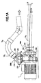
- a counter-current swimming pump 1 comprising a part with its electric motor 10a, which cooperates with a hydraulic part 10b containing an internal blade (not shown), capped by a metal cap 1c comprising two orifices, namely an axial orifice 1b corresponding to a water suction port from a water inlet pipe 10 1 , and a lateral orifice 1a, or discharge port, allowing the discharge in one direction tangential, compared to the circular movement of water circulating inside the hood 1c circular section, water in a pipe 10 2 .
- the pump 1 according to the invention comprises two connectors 200a and 200b according to the invention, comprising spherical ball joints 210.
- the spherical ball joints according to the invention make it possible to connect the pump to inflows 10 3 of said pipes 10 1 and 10 2 of suction and discharge of water, which are not arranged at 90 °, and this thanks to the rotation of the spherical ball of said connectors, as will be explained below.
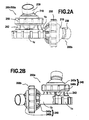
- the spherical hinges 210 of the connectors 200a and 200b are pivoted in two opposite extreme positions, extreme positions also illustrated on the Figures 2A and 2B with regard to the connection 200b.
- a pump equipped with spherical ball joints according to the invention allows at least one of the water circulation pipes 10 1 , 10 2 , at its end on the side of the connection to the pump, to be inclined so that the axis of said pipe at its end 3 is inclined with respect to the axis of the orifice to which it is connected via said coupling, and when the two suction and discharge pipes are inclined with respect to the axis of symmetry of the orifice of the pump with which they cooperate, the angle of inclination may be different in both cases.
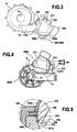
- the sealing of the connection 200a, 200b, at the junction between said first portion 240a and second portion 240b of support members, is completed by two other O-rings 245 and 246.
- the second O-ring 245 is interposed between the first spherical concave surface 241a and the spherical convex surface 211.
- the third O-ring 246 is interposed between the first spherical concave surface 241a of said first support part. and the convex spherical surface 211 of the spherical ball.
- Said second O-ring 245 and third O-ring 246 are located, respectively, near the end of said second and first spherical concave surfaces 241b and 241a, on either side and in proximity to said first O-ring 244.
- a fourth O-ring 247 is placed which also seals between the convex spherical surface 211 and the second spherical concave surface 241b.
- the spherical ball joint 200a which cooperates with the suction orifice 1a, has a first part 240a of support piece which has on the underside ribs or reinforcing edges 242 that bear against the upper surface of the 1c cover, around the suction port 1a, given that the water flow tends to crush the support piece against said hood in the direction of water flow from the outside to the inside the pump at this level.
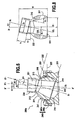
- the frustoconical surface of the frustoconical cavity 220 has an inclination ⁇ 3 of about 25 ° relative to said first axis of revolution X 1 X ' 1 of said frustoconical cavity 220.
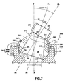
- the second axis of revolution X 2 X ' 2 of the cylindrical nozzle 230 is inclined at an angle ⁇ 2 of 13 ° with respect to said first axis of revolution X 1 X' 1 of the frustoconical internal cavity 220 of the ball 210.
- the ball 210 can pivot by an angle ⁇ 1 relative to the axis XX 'of said central orifice 243 or the orifice 1a, 1b of the pump, less than or equal to ⁇ 1 max of 17 °.
- the spherical ball is in the minimum rotational position, its first axis of revolution X 1 X ' 1 being inclined by an angle - ( ⁇ 1 max - ⁇ 2 ) with respect to the axis XX' of the orifice 1b, 1b of the pump and the central orifice 243 of said support piece 240.
- the base 213 of the beveled end of the cylindrical end piece 230 at the level of the meeting of its large side with the concave surface spherical 211, abuts against the end 248 of the second portion 240b of the support piece, substantially at the fourth O-ring 247.
- the convex spherical surface 211 delimited between the two section planes 221 and 222 must be sufficiently long in the direction of the axis X 1 X ' 1 so that said spherical convex surface always remains supported on a said first and second concave spherical bearing surfaces, but not too long for the end 214 of said spherical convex surface 211 n does not encroach on the central orifice 243, the choice of the values of the angles ⁇ 2 and ⁇ 1 max mentioned above makes it possible to reconcile these two requirements.
- the axis X 2 X' 2 can pivot relative to an axis perpendicular to XX 'and be inclined with respect to the axis XX' of the central orifice 243 of a value of -
- the diameter D2 of the tubular internal cavity 231 of the cylindrical nozzle 230 is slightly greater than the diameter D1 of the central orifice 243 because the ends of the pipes 10 1 , 10 2 , of the same diameter D1 as the central orifice 243 or diameter of the pump orifice, come to get inside the cylindrical nozzle 230.
- This counter-current swimming pump 1 is intended, of course, to be connected to circuits of water pipes supplying a swimming pool, at the level of water delivery nozzles on a side wall of the swimming pool, to create a current, especially in the case of swimming against the current.
- an installation according to the invention may comprise spherical ball joints mounted on the discharge and suction ports of a filtration pump further comprising a filter chamber interposed between the orifice suction pump and the bonnet of the hydraulic part of the pump.
- said cover 1c closes the turbine casing body enclosing the impeller in the form of a fin or blade, mounted in axial rotation in the turbine casing body 10b.
- the turbine casing body 10b is mounted in attachment with the electric motor 10a.
- the couplings according to the present invention can be applied to hydraulic pumps for swimming pools, more particularly to a pump comprising a body of hydraulic part adapted to cooperate with a body of electric pump motor, said body of hydraulic part.
- a pre-filter body comprising a suction port adapted to cooperate with a rigid pipe for the supply of water from a pool
- said pre-filter body comprising or being able to cooperate with a turbine casing body comprising a discharge orifice whose cover 1c comprises a tangential discharge orifice adapted to discharge water in a pipe towards the pool, preferably via a filter to sand or other water treatment accessory for example, when said turbine is rotated by an electric motor cooperating with said casing body.
- the pre-filter body is in relative depression when the pump is running, the water arrives in the pre-filter body via said suction orifice, passes through a filtration system inside the pre-filter body, in particular basket type, before arriving in the casing body of the turbine to be discharged by said discharge port towards the sand filter or other water treatment accessory.
- Spherical ball joints according to the invention may in particular be used in a pump as described in French patent application no. 07 59635 .
Landscapes
- Engineering & Computer Science (AREA)
- Architecture (AREA)
- Mechanical Engineering (AREA)
- General Engineering & Computer Science (AREA)
- Water Supply & Treatment (AREA)
- Civil Engineering (AREA)
- Structural Engineering (AREA)
- Structures Of Non-Positive Displacement Pumps (AREA)
- Joints Allowing Movement (AREA)
- Filtration Of Liquid (AREA)
- Pens And Brushes (AREA)
- Quick-Acting Or Multi-Walled Pipe Joints (AREA)
Claims (11)
- Schwimmbadhydraulikpumpe (1) mit Anschlußelementen zum Anschluß (200, 200a, 200b) an eine Rohrleitung für den Umlauf (101, 102) eines Fluids, vorzugsweise eines Schwimmbeckens oder Bassins, im Bereich der Fluidansaugöffnung (1a) der Pumpe und/oder der Fluidaustrittsöffnung (1 b) der Pumpe, wobei die Pumpe wenigstens ein Anschlußelement (200) umfaßt, das im Bereich einer Austrittsöffnung (1 b) oder Ansaugöffnung (1a) in die Pumpe integriert ist, dadurch gekennzeichnet, daß das Anschlußelement, welches ein Kugelgelenk (210) umfaßt, mit einem rohrförmigen, zylindrischen Ansatzstück (230) abschließt, das geeignet ist, am Ende eines Fluidumlaufrohrs (101, 102) aufgesteckt zu werden, und daß die Rotationsachse (X2X'2) des zylindrischen Ansatzstücks (230) gegenüber der Rotationsachse (X1X'1) des Innenhohlraums (220) des Kugelgelenks geneigt (α2) ist, so daß die Rotationsachse (X2X'2) des zylindrischen Ansatzstücks (230) sich in allen Drehrichtungen gegenüber der Achse (XX') der Austritts- und/oder Ansaugöffnung der Pumpe drehen kann, und gegenüber der Achse (XX') der Öffnung der Pumpe eine Neigung um einen Winkel α aufweist, der im Absolutwert kleiner oder gleich αmax ist, wobei αmax 25° bis 60°, vorzugsweise 30° bis 45° beträgt.
- Pumpe nach Anspruch 1, dadurch gekennzeichnet, daß die Rotationsachse (X2X'2) des zylindrischen Ansatzstücks (230), welche als zweite Achse bezeichnet wird, um einen festen Winkel α2 mit einem Wert zwischen 10° und 30°, vorzugsweise zwischen 10° und 20°, gegenüber der Rotationsachse (X1X'1) des Innenhohlraums (220) des Kugelgelenks (210), welche als erste Achse bezeichnet wird, geneigt ist und das Kugelgelenk (210) sich um einen Winkel α1 von -α1max bis +α1max zwischen seiner ersten Achse (X1X'1) und der Achse der Öffnung der Pumpe (XX') in jeder Drehrichtung gegenüber der Achse (XX') der Öffnung der Pumpe drehen kann, wobei α1max 15° bis 30°, vorzugsweise 15° bis 25° beträgt, so daß die Rotationsachse (X2X'2) des zylindrischen Ansatzstücks (230) sich gegenüber einer zur Achse (XX') der Öffnung der Pumpe senkrecht verlaufenden Achse um einen Wert von - α1max-α2 bis (α1max+α2), in einer gegebenen, durch die erste Achse (X1X'1) und die zweite Achse (X2X'2) verlaufenden Ebene, in einer gegebenen Drehrichtung gegenüber der Achse (XX') der Öffnung der Pumpe drehen kann.
- Pumpe nach Anspruch 2, dadurch gekennzeichnet, daß α1max im wesentlichen gleich dem Winkel α2, mit einem Wert zwischen 15° und 25°, vorzugsweise mit einem Wert von 22,5° ist.
- Pumpe nach Anspruch 3, dadurch gekennzeichnet, daß:- die Öffnung (1a, 1b) der Pumpe durch ein Anlageteil (240a-240b) eingefaßt ist, das eine konkave, kugelförmige Anlagefläche (241 a-241 b) aufweist, die eine mittlere Öffnung (243), welche mit der Öffnung der Pumpe (1 a-1 b) zusammenwirkt, umfaßt und die die gleiche Rotationachse wie die Achse (XX') der Öffnung der Pumpe (1 a-1 b) aufweist, und- das Kugelgelenk (210) eine konvexe, kugelförmige Außenfläche (211) umfaßt, die geeignet ist, sich an der konkaven Anlagefläche (241) zu drehen, wobei die konvexe, kugelförmige Außenfläche durch einen Kugelabschnitt zwischen zwei zu einer Rotationsachse, sogenannten ersten Achse (X1X'1), senkrechten Querschnittsebenen definiert ist, umfassend eine erste Querschnittsebene (222), die einen Querschnitt mit kleinem Durchmesser definiert, und eine zweite Querschnittsebene (221), die einen Querschnitt mit größerem Durchmesser definiert, und wobei das Kugelgelenk (210) ferner einen Innenhohlraum (220) für den Fluiddurchlaß umfaßt, der durch eine kegelstumpfartige Rotationsfläche mit gerader oder gekrümmter Mantellinie mit einer Konvexität auf der Seite des Innenraums des Hohlraums, um eine der ersten Achse (X1X'1) entsprechende Rotationsachse begrenzt ist, so daß die sogenannte zweite Achse (X2X'2) des zylindrischen Ansatzstücks (230) sich bis zu einem Wert αmax = α1max + α2 in jeder Drehrichtung gegenüber der Achse (XX') der mittleren Öffnung (243) drehen kann, wobei der kegelstumpfförmige Hohlraum eine offene, kreisförmige kleine Basis im Bereich der ersten Querschnittsebene (222) und eine kreisförmige, offene große Basis im Bereich der zweiten Querschnittsebene (221) aufweist, und- ein rohrförmiges, zylindrisches Ansatzstück (230) sich von der ersten Querschnittsebene (222) aus erstreckt, die zweite Achse (X2X'2) um einen Winkel α2 gegenüber der ersten Achse (X1X'1) des kegelstumpfförmigen Innenhohlraums (220) geneigt ist, der kegelstumpfförmige Innenhohlraum (220), welcher durch den rohrförmigen Innenhohlraum (231) des rohrförmigen, zylindrischen Ansatzstücks fortgesetzt ist, ein abgeschrägtes Ende aufweist, dessen Öffnung im Bereich der offenen, kreisförmigen kleinen Basis des kegelstumpfförmigen Innenhohlraums im Bereich der ersten Querschnittsebene (222) zu liegen kommt, sowie ein zweites rohrförmiges Ende, das geeignet ist, auf das Ende eines Wasserumlaufrohrs (101, 102) aufgesteckt zu werden.
- Pumpe nach Anspruch 4, dadurch gekennzeichnet, daß das Anschlußelement (200a, 200b) mit Kugelgelenk eine konkave Kugelfläche (241) aufweist, die im Bereich einer dritten Querschnittsebene (223) in zwei Teile (241 a, 241 b) geteilt ist, so daß das Anlageteil (240) einen ersten unteren Anlageteilabschnitt (240a) mit einer ersten konkaven Kugelfläche (241 a) um die Öffnung der Pumpe umfaßt, worauf ein zweiter kragenförmiger oberer Anlageteilabschnitt (240b) zur Anlage kommt, dessen zweite konkave Kugelfläche (241 b) die erste konkave Kugelfläche (241 a) fortsetzt, wobei der zweite kragenförmige obere Anlageteilabschnitt (240b) durch eine Klemmschelle (250), mit Hilfe eines O-Rings (244) dicht an dem ersten unteren Anlageteilabschnitt (240a) gehalten ist.
- Pumpe nach Anspruch 5, dadurch gekennzeichnet, daß die Klemmschelle (250) ein zylindrisches Gewinde aufweist, das geeignet ist, mit einem ergänzenden Gewinde an dem zylindrischen Außenumfang des oberen Teils des ersten unteren Anlageteilabschnitts (240a) schließend zusammenzuwirken.
- Pumpe nach einem der Ansprüche 4 bis 6, dadurch gekennzeichnet, daß der kegelstumpfförmige Innenhohlraum (220) eine gerade Mantellinie aufweist, die um einen Winkel (α3) von 20° bis 30°, vorzugsweise etwa 25°, gegenüber der ersten Rotationsachse (X1X'1) geneigt ist.
- Pumpe nach einem der Ansprüche 1 bis 7, dadurch gekennzeichnet, daß sie ein kugelförmiges Anschlußelement an jeder ihrer beiden Öffnungen, Ansaugöffnung (1a) und Austrittsöffnung (1b), aufweist, deren Symmetrieachsen senkrecht angeordnet sind.
- Pumpe nach Anspruch 8, dadurch gekennzeichnet, daß die Achse der Ansaugöffnung im wesentlichen horizontal verläuft und die Achse der Austrittsöffnung im wesentlichen senkrecht, oberhalb der Ansaugöffnung gelegen ist.
- Wasserumwälzanlage für ein Schwimmbad, umfassend eine Filtrationspumpe oder eine Pumpe zum Gegenstromschwimmen nach einem der Ansprüche 1 bis 9, die im Bereich wenigstens eines Anschlußelements, im Bereich einer Wasseransaugöffnung (1 a) oder -austrittsöffnung (1 b) der Pumpe mit Rohren für den Wasserumlauf (101, 102) verbunden ist, wobei das Ende des Rohres, das im Bereich des zylindrischen, rohrförmigen Ansatzstücks (230) des Anschlußelements (200a, 200b) aufgesteckt ist, gegenüber der Symmetrieachse (XX') der Öffnung geneigt ist.
- Anlage nach Anspruch 10, dadurch gekennzeichnet, daß die Pumpe zwei Anschlußelemente (200a, 200b) mit Kugelgelenk umfaßt und die Rohre (101, 102) im Bereich der beiden Anschlußelemente mit unterschiedlicher Neigung gegenüber der Achse (XX') der Öffnung der Pumpe geneigt sind.
Applications Claiming Priority (1)
| Application Number | Priority Date | Filing Date | Title |
|---|---|---|---|
| FR0852835A FR2930602A1 (fr) | 2008-04-28 | 2008-04-28 | Pompe hydraulique a raccord a rotule spherique |
Publications (2)
| Publication Number | Publication Date |
|---|---|
| EP2113705A1 EP2113705A1 (de) | 2009-11-04 |
| EP2113705B1 true EP2113705B1 (de) | 2011-02-23 |
Family
ID=39968050
Family Applications (1)
| Application Number | Title | Priority Date | Filing Date |
|---|---|---|---|
| EP20090153206 Not-in-force EP2113705B1 (de) | 2008-04-28 | 2009-02-19 | Hydraulische Pumpe mit einem kugelgelenkförmigen Anschluss |
Country Status (6)
| Country | Link |
|---|---|
| US (1) | US20090267344A1 (de) |
| EP (1) | EP2113705B1 (de) |
| AT (1) | ATE499566T1 (de) |
| DE (1) | DE602009000762D1 (de) |
| ES (1) | ES2361240T3 (de) |
| FR (1) | FR2930602A1 (de) |
Families Citing this family (10)
| Publication number | Priority date | Publication date | Assignee | Title |
|---|---|---|---|---|
| FR3022575B1 (fr) * | 2014-06-23 | 2016-07-22 | Acis (Aqua Consult Ind Services) | Pompe de filtration pour piscine |
| CN104131981B (zh) * | 2014-07-17 | 2016-04-13 | 华泽遂 | V型多向油料输送泵及其使用方法 |
| EP3147514B1 (de) * | 2015-09-23 | 2020-02-26 | Inbrooll Industries, SL | Pumpe mit anpassbaren saug- und druckstutzen |
| US11156219B2 (en) | 2015-11-10 | 2021-10-26 | Repligen Corporation | Disposable alternating tangential flow filtration units |
| DK3299633T3 (da) * | 2016-09-26 | 2023-03-13 | Bosch Gmbh Robert | Cirkulationspumpesystem |
| GB201713232D0 (en) | 2017-08-17 | 2017-10-04 | Mcalpine & Co Ltd | Plumbing connector, assembly and associated methods |
| US11236522B2 (en) * | 2018-09-21 | 2022-02-01 | Daniel Marano | Pool nozzle |
| CN110886342B (zh) * | 2019-12-03 | 2021-09-17 | 盐城国睿信科技有限公司 | 一种郊外工程建设混凝土搅拌用河流取水设备 |
| EP3926797A1 (de) | 2020-06-19 | 2021-12-22 | EasyFlow Oü | Pumpenverbindungs- und -anpassungssystem |
| DE202021002703U1 (de) * | 2021-08-18 | 2021-10-05 | Denis Drosdzol | Umkippschutz für Tauchpumpen, mit orthogonal zur Bezugsoberfläche abgehender Schlauchleitung, mittels Vorrichtung zur horizontalen Schwerpunktverlagerung und Kraftableitung |
Family Cites Families (8)
| Publication number | Priority date | Publication date | Assignee | Title |
|---|---|---|---|---|
| US4045054A (en) * | 1972-09-28 | 1977-08-30 | Hydrotech International, Inc. | Apparatus for rigidly interconnecting misaligned pipe ends |
| US4180285A (en) * | 1978-05-11 | 1979-12-25 | Reneau Bobby J | Articulated ball connector for use with pipeline |
| AU4757985A (en) * | 1984-11-05 | 1986-05-15 | Alopex Industries Inc. | Adaptor fitting for swimming pool filtration system |
| ES1019424Y (es) * | 1991-11-13 | 1992-10-16 | Doll, S.A. | Prefiltro para instalaciones de piscinas. |
| AU2746300A (en) * | 1999-02-01 | 2000-08-18 | Polaris Pool Systems, Inc. | Swivel coupling for a pool cleaner |
| ES1044076Y (es) * | 1999-08-04 | 2000-08-16 | Sacopa Sa | Dispositivo para la limpieza de fondos de piscinas. |
| EP1711709A2 (de) * | 2004-01-16 | 2006-10-18 | Polaris Pool Systems, Inc. | Motorgetriebene pumpe für becken oder bad |
| US7490868B2 (en) * | 2006-07-13 | 2009-02-17 | Prestridge John M | Pipe mating swivel adapter for misaligned joints |
-
2008
- 2008-04-28 FR FR0852835A patent/FR2930602A1/fr not_active Withdrawn
-
2009
- 2009-02-19 AT AT09153206T patent/ATE499566T1/de not_active IP Right Cessation
- 2009-02-19 DE DE200960000762 patent/DE602009000762D1/de active Active
- 2009-02-19 ES ES09153206T patent/ES2361240T3/es active Active
- 2009-02-19 EP EP20090153206 patent/EP2113705B1/de not_active Not-in-force
- 2009-02-23 US US12/390,896 patent/US20090267344A1/en not_active Abandoned
Also Published As
| Publication number | Publication date |
|---|---|
| EP2113705A1 (de) | 2009-11-04 |
| US20090267344A1 (en) | 2009-10-29 |
| ES2361240T3 (es) | 2011-06-15 |
| FR2930602A1 (fr) | 2009-10-30 |
| DE602009000762D1 (de) | 2011-04-07 |
| ATE499566T1 (de) | 2011-03-15 |
Similar Documents
| Publication | Publication Date | Title |
|---|---|---|
| EP2113705B1 (de) | Hydraulische Pumpe mit einem kugelgelenkförmigen Anschluss | |
| EP1110023B1 (de) | Abgedichtete kupplung mit verstellbarer geometrie | |
| EP2071194B1 (de) | Hydraulikpumpe, die einen Vorfilterkörper aus zwei verdrehbaren Teilen umfasst | |
| EP3158146B1 (de) | Filterpumpe für ein schwimmbecken | |
| EP1220969B1 (de) | Leitungssystem für eine pumpen- und filtereinrichtung in einem schwimmbecken | |
| WO2011098680A1 (fr) | Robinet a double papillons | |
| BE538717A (de) | ||
| FR2957999A1 (fr) | Piston avec un conduit sous joint | |
| FR2800401A1 (fr) | Dispositif a raccord amovible et a clapet commande pour reseau d'adduction d'eau et ensemble de comptage le mettant en oeuvre | |
| WO2019081500A1 (fr) | Mitigeur et procédé d'interversion d'un tel mitigeur | |
| EP2365295B1 (de) | Zähler mit normierter Ultraschall-Messzelle vom Kapseltyp | |
| EP1925756A1 (de) | Untersuchungsbrunnen für Kanalisationsnetz, der mindestens einen Anschlussstutzen mit einem schwenkbaren Verbindungselement umfasst | |
| FR2553489A1 (fr) | Robinet d'arret pour liquides | |
| WO2000001974A1 (fr) | Procede de montage d'un raccord a l'extremite d'un tube et nouveau type de raccord permettant sa mise en oeuvre | |
| EP0622496B1 (de) | Verfahren zur Herstellung eines Mannloches | |
| FR2961886A1 (fr) | Systeme de raccord a deux pieces destine a un tuyau a deux lumieres | |
| FR2554538A1 (fr) | Joint d'etancheite pour branchement d'un element tubulaire sur un tuyau de plus grand diametre | |
| EP3431845A1 (de) | Ventilhahn, der einen hahnkegel und eine reissfeste vorrichtung zur verhinderung von rissbildung des kegels in der frostperiode umfasst | |
| EP0092495A1 (de) | Weinleseventile | |
| FR3004777A1 (fr) | Dispositif de vanne a papillon incline. | |
| FR2987094A1 (fr) | Robinet a papillon | |
| FR3072752A1 (fr) | Ensemble interne pour un mitigeur | |
| FR3166157A3 (fr) | Pompe réglable | |
| EP2980336B1 (de) | Anschlussvorrichtung eines geräts oder eines organs an eine rücklaufdüse mit kugelgelenk | |
| EP1574717B1 (de) | Pumpe |
Legal Events
| Date | Code | Title | Description |
|---|---|---|---|
| PUAI | Public reference made under article 153(3) epc to a published international application that has entered the european phase |
Free format text: ORIGINAL CODE: 0009012 |
|
| AK | Designated contracting states |
Kind code of ref document: A1 Designated state(s): AT BE BG CH CY CZ DE DK EE ES FI FR GB GR HR HU IE IS IT LI LT LU LV MC MK MT NL NO PL PT RO SE SI SK TR |
|
| AX | Request for extension of the european patent |
Extension state: AL BA RS |
|
| 17P | Request for examination filed |
Effective date: 20100308 |
|
| 17Q | First examination report despatched |
Effective date: 20100326 |
|
| AKX | Designation fees paid |
Designated state(s): AT BE BG CH CY CZ DE DK EE ES FI FR GB GR HR HU IE IS IT LI LT LU LV MC MK MT NL NO PL PT RO SE SI SK TR |
|
| GRAP | Despatch of communication of intention to grant a patent |
Free format text: ORIGINAL CODE: EPIDOSNIGR1 |
|
| GRAS | Grant fee paid |
Free format text: ORIGINAL CODE: EPIDOSNIGR3 |
|
| GRAA | (expected) grant |
Free format text: ORIGINAL CODE: 0009210 |
|
| AK | Designated contracting states |
Kind code of ref document: B1 Designated state(s): AT BE BG CH CY CZ DE DK EE ES FI FR GB GR HR HU IE IS IT LI LT LU LV MC MK MT NL NO PL PT RO SE SI SK TR |
|
| REG | Reference to a national code |
Ref country code: GB Ref legal event code: FG4D Free format text: NOT ENGLISH |
|
| REG | Reference to a national code |
Ref country code: CH Ref legal event code: EP |
|
| REG | Reference to a national code |
Ref country code: IE Ref legal event code: FG4D Free format text: LANGUAGE OF EP DOCUMENT: FRENCH |
|
| REF | Corresponds to: |
Ref document number: 602009000762 Country of ref document: DE Date of ref document: 20110407 Kind code of ref document: P |
|
| REG | Reference to a national code |
Ref country code: DE Ref legal event code: R096 Ref document number: 602009000762 Country of ref document: DE Effective date: 20110407 |
|
| REG | Reference to a national code |
Ref country code: ES Ref legal event code: FG2A Ref document number: 2361240 Country of ref document: ES Kind code of ref document: T3 Effective date: 20110615 |
|
| REG | Reference to a national code |
Ref country code: NL Ref legal event code: VDEP Effective date: 20110223 |
|
| LTIE | Lt: invalidation of european patent or patent extension |
Effective date: 20110223 |
|
| PG25 | Lapsed in a contracting state [announced via postgrant information from national office to epo] |
Ref country code: GR Free format text: LAPSE BECAUSE OF FAILURE TO SUBMIT A TRANSLATION OF THE DESCRIPTION OR TO PAY THE FEE WITHIN THE PRESCRIBED TIME-LIMIT Effective date: 20110524 Ref country code: SE Free format text: LAPSE BECAUSE OF FAILURE TO SUBMIT A TRANSLATION OF THE DESCRIPTION OR TO PAY THE FEE WITHIN THE PRESCRIBED TIME-LIMIT Effective date: 20110223 Ref country code: LV Free format text: LAPSE BECAUSE OF FAILURE TO SUBMIT A TRANSLATION OF THE DESCRIPTION OR TO PAY THE FEE WITHIN THE PRESCRIBED TIME-LIMIT Effective date: 20110223 Ref country code: HR Free format text: LAPSE BECAUSE OF FAILURE TO SUBMIT A TRANSLATION OF THE DESCRIPTION OR TO PAY THE FEE WITHIN THE PRESCRIBED TIME-LIMIT Effective date: 20110223 Ref country code: LT Free format text: LAPSE BECAUSE OF FAILURE TO SUBMIT A TRANSLATION OF THE DESCRIPTION OR TO PAY THE FEE WITHIN THE PRESCRIBED TIME-LIMIT Effective date: 20110223 Ref country code: NO Free format text: LAPSE BECAUSE OF FAILURE TO SUBMIT A TRANSLATION OF THE DESCRIPTION OR TO PAY THE FEE WITHIN THE PRESCRIBED TIME-LIMIT Effective date: 20110523 Ref country code: PT Free format text: LAPSE BECAUSE OF FAILURE TO SUBMIT A TRANSLATION OF THE DESCRIPTION OR TO PAY THE FEE WITHIN THE PRESCRIBED TIME-LIMIT Effective date: 20110623 |
|
| PG25 | Lapsed in a contracting state [announced via postgrant information from national office to epo] |
Ref country code: CY Free format text: LAPSE BECAUSE OF FAILURE TO SUBMIT A TRANSLATION OF THE DESCRIPTION OR TO PAY THE FEE WITHIN THE PRESCRIBED TIME-LIMIT Effective date: 20110223 Ref country code: FI Free format text: LAPSE BECAUSE OF FAILURE TO SUBMIT A TRANSLATION OF THE DESCRIPTION OR TO PAY THE FEE WITHIN THE PRESCRIBED TIME-LIMIT Effective date: 20110223 Ref country code: BG Free format text: LAPSE BECAUSE OF FAILURE TO SUBMIT A TRANSLATION OF THE DESCRIPTION OR TO PAY THE FEE WITHIN THE PRESCRIBED TIME-LIMIT Effective date: 20110523 Ref country code: NL Free format text: LAPSE BECAUSE OF FAILURE TO SUBMIT A TRANSLATION OF THE DESCRIPTION OR TO PAY THE FEE WITHIN THE PRESCRIBED TIME-LIMIT Effective date: 20110223 Ref country code: AT Free format text: LAPSE BECAUSE OF FAILURE TO SUBMIT A TRANSLATION OF THE DESCRIPTION OR TO PAY THE FEE WITHIN THE PRESCRIBED TIME-LIMIT Effective date: 20110223 Ref country code: SI Free format text: LAPSE BECAUSE OF FAILURE TO SUBMIT A TRANSLATION OF THE DESCRIPTION OR TO PAY THE FEE WITHIN THE PRESCRIBED TIME-LIMIT Effective date: 20110223 |
|
| REG | Reference to a national code |
Ref country code: IE Ref legal event code: FD4D |
|
| PG25 | Lapsed in a contracting state [announced via postgrant information from national office to epo] |
Ref country code: EE Free format text: LAPSE BECAUSE OF FAILURE TO SUBMIT A TRANSLATION OF THE DESCRIPTION OR TO PAY THE FEE WITHIN THE PRESCRIBED TIME-LIMIT Effective date: 20110223 Ref country code: DK Free format text: LAPSE BECAUSE OF FAILURE TO SUBMIT A TRANSLATION OF THE DESCRIPTION OR TO PAY THE FEE WITHIN THE PRESCRIBED TIME-LIMIT Effective date: 20110223 Ref country code: IE Free format text: LAPSE BECAUSE OF FAILURE TO SUBMIT A TRANSLATION OF THE DESCRIPTION OR TO PAY THE FEE WITHIN THE PRESCRIBED TIME-LIMIT Effective date: 20110223 |
|
| PG25 | Lapsed in a contracting state [announced via postgrant information from national office to epo] |
Ref country code: RO Free format text: LAPSE BECAUSE OF FAILURE TO SUBMIT A TRANSLATION OF THE DESCRIPTION OR TO PAY THE FEE WITHIN THE PRESCRIBED TIME-LIMIT Effective date: 20110223 Ref country code: SK Free format text: LAPSE BECAUSE OF FAILURE TO SUBMIT A TRANSLATION OF THE DESCRIPTION OR TO PAY THE FEE WITHIN THE PRESCRIBED TIME-LIMIT Effective date: 20110223 Ref country code: CZ Free format text: LAPSE BECAUSE OF FAILURE TO SUBMIT A TRANSLATION OF THE DESCRIPTION OR TO PAY THE FEE WITHIN THE PRESCRIBED TIME-LIMIT Effective date: 20110223 |
|
| PLBE | No opposition filed within time limit |
Free format text: ORIGINAL CODE: 0009261 |
|
| STAA | Information on the status of an ep patent application or granted ep patent |
Free format text: STATUS: NO OPPOSITION FILED WITHIN TIME LIMIT |
|
| 26N | No opposition filed |
Effective date: 20111124 |
|
| PG25 | Lapsed in a contracting state [announced via postgrant information from national office to epo] |
Ref country code: PL Free format text: LAPSE BECAUSE OF FAILURE TO SUBMIT A TRANSLATION OF THE DESCRIPTION OR TO PAY THE FEE WITHIN THE PRESCRIBED TIME-LIMIT Effective date: 20110223 |
|
| REG | Reference to a national code |
Ref country code: DE Ref legal event code: R097 Ref document number: 602009000762 Country of ref document: DE Effective date: 20111124 |
|
| PGFP | Annual fee paid to national office [announced via postgrant information from national office to epo] |
Ref country code: IT Payment date: 20120228 Year of fee payment: 4 |
|
| BERE | Be: lapsed |
Owner name: GATECH Effective date: 20120228 |
|
| PG25 | Lapsed in a contracting state [announced via postgrant information from national office to epo] |
Ref country code: MC Free format text: LAPSE BECAUSE OF NON-PAYMENT OF DUE FEES Effective date: 20120229 |
|
| REG | Reference to a national code |
Ref country code: FR Ref legal event code: ST Effective date: 20121031 |
|
| REG | Reference to a national code |
Ref country code: DE Ref legal event code: R119 Ref document number: 602009000762 Country of ref document: DE Effective date: 20120901 |
|
| PG25 | Lapsed in a contracting state [announced via postgrant information from national office to epo] |
Ref country code: BE Free format text: LAPSE BECAUSE OF NON-PAYMENT OF DUE FEES Effective date: 20120228 |
|
| PG25 | Lapsed in a contracting state [announced via postgrant information from national office to epo] |
Ref country code: FR Free format text: LAPSE BECAUSE OF NON-PAYMENT OF DUE FEES Effective date: 20120229 |
|
| PG25 | Lapsed in a contracting state [announced via postgrant information from national office to epo] |
Ref country code: MK Free format text: LAPSE BECAUSE OF FAILURE TO SUBMIT A TRANSLATION OF THE DESCRIPTION OR TO PAY THE FEE WITHIN THE PRESCRIBED TIME-LIMIT Effective date: 20110223 |
|
| PG25 | Lapsed in a contracting state [announced via postgrant information from national office to epo] |
Ref country code: DE Free format text: LAPSE BECAUSE OF NON-PAYMENT OF DUE FEES Effective date: 20120901 |
|
| PG25 | Lapsed in a contracting state [announced via postgrant information from national office to epo] |
Ref country code: MT Free format text: LAPSE BECAUSE OF FAILURE TO SUBMIT A TRANSLATION OF THE DESCRIPTION OR TO PAY THE FEE WITHIN THE PRESCRIBED TIME-LIMIT Effective date: 20110223 |
|
| REG | Reference to a national code |
Ref country code: CH Ref legal event code: PL |
|
| GBPC | Gb: european patent ceased through non-payment of renewal fee |
Effective date: 20130219 |
|
| PG25 | Lapsed in a contracting state [announced via postgrant information from national office to epo] |
Ref country code: LI Free format text: LAPSE BECAUSE OF NON-PAYMENT OF DUE FEES Effective date: 20130228 Ref country code: CH Free format text: LAPSE BECAUSE OF NON-PAYMENT OF DUE FEES Effective date: 20130228 |
|
| PG25 | Lapsed in a contracting state [announced via postgrant information from national office to epo] |
Ref country code: IT Free format text: LAPSE BECAUSE OF NON-PAYMENT OF DUE FEES Effective date: 20130219 |
|
| PG25 | Lapsed in a contracting state [announced via postgrant information from national office to epo] |
Ref country code: GB Free format text: LAPSE BECAUSE OF NON-PAYMENT OF DUE FEES Effective date: 20130219 |
|
| PG25 | Lapsed in a contracting state [announced via postgrant information from national office to epo] |
Ref country code: TR Free format text: LAPSE BECAUSE OF FAILURE TO SUBMIT A TRANSLATION OF THE DESCRIPTION OR TO PAY THE FEE WITHIN THE PRESCRIBED TIME-LIMIT Effective date: 20110223 |
|
| REG | Reference to a national code |
Ref country code: ES Ref legal event code: FD2A Effective date: 20140527 |
|
| PG25 | Lapsed in a contracting state [announced via postgrant information from national office to epo] |
Ref country code: LU Free format text: LAPSE BECAUSE OF NON-PAYMENT OF DUE FEES Effective date: 20120219 Ref country code: ES Free format text: LAPSE BECAUSE OF NON-PAYMENT OF DUE FEES Effective date: 20110220 |
|
| PG25 | Lapsed in a contracting state [announced via postgrant information from national office to epo] |
Ref country code: HU Free format text: LAPSE BECAUSE OF FAILURE TO SUBMIT A TRANSLATION OF THE DESCRIPTION OR TO PAY THE FEE WITHIN THE PRESCRIBED TIME-LIMIT Effective date: 20090219 |
|
| PG25 | Lapsed in a contracting state [announced via postgrant information from national office to epo] |
Ref country code: IS Free format text: LAPSE BECAUSE OF FAILURE TO SUBMIT A TRANSLATION OF THE DESCRIPTION OR TO PAY THE FEE WITHIN THE PRESCRIBED TIME-LIMIT Effective date: 20110223 |