EP0622511A2 - Ausstellvorrichtung für einen Dreh-Kipp-Flügel - Google Patents
Ausstellvorrichtung für einen Dreh-Kipp-Flügel Download PDFInfo
- Publication number
- EP0622511A2 EP0622511A2 EP94101348A EP94101348A EP0622511A2 EP 0622511 A2 EP0622511 A2 EP 0622511A2 EP 94101348 A EP94101348 A EP 94101348A EP 94101348 A EP94101348 A EP 94101348A EP 0622511 A2 EP0622511 A2 EP 0622511A2
- Authority
- EP
- European Patent Office
- Prior art keywords
- guide part
- housing
- scissor housing
- scissor
- extension arm
- Prior art date
- Legal status (The legal status is an assumption and is not a legal conclusion. Google has not performed a legal analysis and makes no representation as to the accuracy of the status listed.)
- Granted
Links
- 239000011324 bead Substances 0.000 claims description 3
- 239000013589 supplement Substances 0.000 abstract 1
- 238000010276 construction Methods 0.000 description 4
- 230000001419 dependent effect Effects 0.000 description 1
- 239000013013 elastic material Substances 0.000 description 1
- 230000001771 impaired effect Effects 0.000 description 1
- 238000004080 punching Methods 0.000 description 1
Images


Classifications
-
- E—FIXED CONSTRUCTIONS
- E05—LOCKS; KEYS; WINDOW OR DOOR FITTINGS; SAFES
- E05D—HINGES OR SUSPENSION DEVICES FOR DOORS, WINDOWS OR WINGS
- E05D15/00—Suspension arrangements for wings
- E05D15/48—Suspension arrangements for wings allowing alternative movements
- E05D15/52—Suspension arrangements for wings allowing alternative movements for opening about a vertical as well as a horizontal axis
- E05D15/5205—Suspension arrangements for wings allowing alternative movements for opening about a vertical as well as a horizontal axis with horizontally-extending checks
-
- E—FIXED CONSTRUCTIONS
- E05—LOCKS; KEYS; WINDOW OR DOOR FITTINGS; SAFES
- E05C—BOLTS OR FASTENING DEVICES FOR WINGS, SPECIALLY FOR DOORS OR WINDOWS
- E05C17/00—Devices for holding wings open; Devices for limiting opening of wings or for holding wings open by a movable member extending between frame and wing; Braking devices, stops or buffers, combined therewith
- E05C17/02—Devices for holding wings open; Devices for limiting opening of wings or for holding wings open by a movable member extending between frame and wing; Braking devices, stops or buffers, combined therewith by mechanical means
- E05C17/04—Devices for holding wings open; Devices for limiting opening of wings or for holding wings open by a movable member extending between frame and wing; Braking devices, stops or buffers, combined therewith by mechanical means with a movable bar or equivalent member extending between frame and wing
- E05C17/12—Devices for holding wings open; Devices for limiting opening of wings or for holding wings open by a movable member extending between frame and wing; Braking devices, stops or buffers, combined therewith by mechanical means with a movable bar or equivalent member extending between frame and wing consisting of a single rod
- E05C17/24—Devices for holding wings open; Devices for limiting opening of wings or for holding wings open by a movable member extending between frame and wing; Braking devices, stops or buffers, combined therewith by mechanical means with a movable bar or equivalent member extending between frame and wing consisting of a single rod pivoted at one end, and with the other end running along a guide member
- E05C17/28—Devices for holding wings open; Devices for limiting opening of wings or for holding wings open by a movable member extending between frame and wing; Braking devices, stops or buffers, combined therewith by mechanical means with a movable bar or equivalent member extending between frame and wing consisting of a single rod pivoted at one end, and with the other end running along a guide member with braking, clamping or securing means at the connection to the guide member
-
- E—FIXED CONSTRUCTIONS
- E05—LOCKS; KEYS; WINDOW OR DOOR FITTINGS; SAFES
- E05Y—INDEXING SCHEME ASSOCIATED WITH SUBCLASSES E05D AND E05F, RELATING TO CONSTRUCTION ELEMENTS, ELECTRIC CONTROL, POWER SUPPLY, POWER SIGNAL OR TRANSMISSION, USER INTERFACES, MOUNTING OR COUPLING, DETAILS, ACCESSORIES, AUXILIARY OPERATIONS NOT OTHERWISE PROVIDED FOR, APPLICATION THEREOF
- E05Y2201/00—Constructional elements; Accessories therefor
- E05Y2201/20—Brakes; Disengaging means; Holders; Stops; Valves; Accessories therefor
- E05Y2201/218—Holders
-
- E—FIXED CONSTRUCTIONS
- E05—LOCKS; KEYS; WINDOW OR DOOR FITTINGS; SAFES
- E05Y—INDEXING SCHEME ASSOCIATED WITH SUBCLASSES E05D AND E05F, RELATING TO CONSTRUCTION ELEMENTS, ELECTRIC CONTROL, POWER SUPPLY, POWER SIGNAL OR TRANSMISSION, USER INTERFACES, MOUNTING OR COUPLING, DETAILS, ACCESSORIES, AUXILIARY OPERATIONS NOT OTHERWISE PROVIDED FOR, APPLICATION THEREOF
- E05Y2900/00—Application of doors, windows, wings or fittings thereof
- E05Y2900/10—Application of doors, windows, wings or fittings thereof for buildings or parts thereof
- E05Y2900/13—Type of wing
- E05Y2900/148—Windows
Definitions
- the present invention relates to an opening device for a turn-and-tilt sash of a window or a door, with an opening arm which can be connected to a frame of a window or a door in an articulated manner and on the other hand articulated and - within an elongated hole - a scissor housing which can be fixed on the sash side is, with the extension arm a longitudinally displaceably mounted guide part is connected in the elongated hole of the scissor housing and, at the maximum possible pivoting between the extension arm and scissor housing, an unintentional pivoting back is prevented by a non-positive locking.
- Display device of the aforementioned type are known in many embodiments.
- the protection against unintentional pivoting back which is generally referred to as a supplementary security, requires special additional parts on the scissor arm guide and correspondingly designed counterparts.
- the guide bolts of the scissor link arms must be designed in a correspondingly complex manner in order to be able to interact with correspondingly designed locking means on the scissor link base plate.
- the guide pin of the scissor link is loaded on one side in the guide groove, which can lead to higher wear between the pin and the guide.
- the present invention is therefore based on the object of designing an opening device of the generic type with a supplementary lock in such a way that the guiding behavior of the opening arm in the scissor housing is not influenced and that additional locking parts in the scissor housing are unnecessary.
- the fuse consists of a resilient latching part connected to the guide part, which engages behind at least one latching projection arranged in the scissor housing when the extension arm is pivoted out to the maximum extent.
- the entire movement sequence of the opening device is in no way impaired and a particularly simple construction of the supplementary protection is realized.
- a resilient latching part on the guide part of the extension arm, which can be made, for example, in one piece with the guide part or connected to this guide part as a separate component.
- Undercuts, screw heads or the like present on the scissor housing can be used as a locking projection, so that the construction of the scissor housing does not require any special design with regard to the implementation of the additional security.
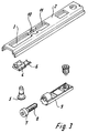
- the reference numeral 1 denotes an opening arm of an opening device which, on the one hand, can be articulated in a manner known per se to a frame of a window or a door and, on the other hand, is articulated and displaceably connected to a scissor-type housing 2.
- the scissor housing 2 has an elongated hole 3 in the connection area of the extension arm 1, in which a guide part 4 is guided so as to be longitudinally displaceable. This guide part 4 is penetrated by a connecting rivet 5 which connects the guide part 4 to the extension arm 1.
- a resilient latching part 6 Connected in one piece to the guide part 4 is a resilient latching part 6, which engages behind the head 7 of an adjusting screw at maximum pivoting between the extension arm 1 and the scissors housing, which screw extends in the longitudinal direction of the scissors housing 2 into a fastening part 9 which is arranged within the scissors housing 2 .
- the head 7 of this adjusting screw 8 serves, as it were, as a latching projection for the latching part 6 connected to the guide part 4. In the latching position shown in FIG.
- the locking part 6 is made in one piece with the guide part 4 from an elastic plastic or another elastic material.
- the scissor housing 2 is provided with cutouts 10 and 11 in the connection area to the elongated hole 3, the head 7 of the fastening screw 8 being arranged axially secured in the cutout 10.
- Figure 4 shows a construction in which the guide part 4 and the locking part 6 are formed in two parts, but are held by the same rivet 5, which also connects the extension arm 1 to the guide part 4.
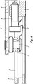
- Figures 5 to 7 show a further embodiment of the invention.
- extension arm 1 is articulated and longitudinally displaceably connected to a scissor housing 2.
- a guide part 4 in turn engages in an elongated hole 3 of the scissor housing 2 and is connected to the extension arm 1 via a rivet 5.
- a latching part 6 is again connected to the guide part 4, which in the case of the exemplary embodiment according to FIGS.
- Figure 8 shows again that the guide part 4 and the locking part 6 can also be designed as separate components.
- FIG. 9 indicates a one-piece embodiment of the guide part 4 and the locking part 6 made of plastic, the locking part 6 again engaging behind the transverse web 12, which limits the elongated hole 3 of the scissor housing 2 on one side, for the purpose of securing the surcharge.
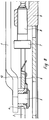
- FIGS. 10 and 11 show, as an alternative latching option, a guide part 4 with an integrally formed latching part 6, which is laterally provided with latching depressions 13.
- beads 14 integrally formed on the side flanks of the scissor housing 2 engage in these latching depressions 13, as FIG. 11 shows particularly clearly. These beads 14 can be formed on the punching of the scissors housing without any significant additional effort.
Landscapes
- Engineering & Computer Science (AREA)
- Mechanical Engineering (AREA)
- Casings For Electric Apparatus (AREA)
- Pivots And Pivotal Connections (AREA)
- Hinges (AREA)
- Lighting Device Outwards From Vehicle And Optical Signal (AREA)
- Connection Of Plates (AREA)
- Jib Cranes (AREA)
- Forklifts And Lifting Vehicles (AREA)
- Earth Drilling (AREA)
Abstract
Description
- Die vorliegende Erfindung betrifft eine Ausstellvorrichtung für einen Dreh-Kipp-Flügel eines Fensters oder einer Tür, mit einem Ausstellarm, der einerseits an einem Blendrahmen eines Fensters oder einer Tür gelenkig anschließbar und andererseits gelenkig und - innerhalb eines Langloches - eines flügelseitig festlegbaren Scherengehäuses verschiebbar gelagert ist, wobei mit dem Ausstellarm ein im Langloch des Scherengehäuses längsverschiebbar gelagertes Führungsteil verbunden ist und bei maximal möglicher Verschwenkung zwischen Ausstellarm und Scherengehäuse durch eine kraftschlüssige Sicherung ein unbeabsichtigtes Zurückschwenken verhindert ist.
- Ausstellvorrichtung der vorerwähnten Art sind in vielerlei Ausführungsformen bekannt.
- Bei den bekannten Ausstellvorrichtungen ist als nachteilig anzusehen, daß die Sicherung gegen unbeabsichtigtes Rückschwenken, die allgemein als Zuschlagsicherung bezeichnet wird, spezielle Zusatzteile an der Scherenlenkerführung sowie entsprechend gestaltete Gegenstücke erfordert. Die Führungsbolzen der Scherenlenker müssen entsprechend aufwendig ausgeformt sein, um mit entsprechend gestalteten Rastmitteln an der Scherenlenkergrundplatte zusammenwirken zu können. Zum Teil werden dabei die Führungsbolzen des Scherenlenkers einseitig in der Führungsnut belastet, was zu punktuell höherem Verschleiß zwischen Bolzen und Führung führen kann.
- Der vorliegenden Erfindung liegt deshalb die Aufgabe zugrunde, eine Ausstellvorrichtung der gattungsgemäßen Art mit einer Zuschlagsicherung so zu gestalten, daß das Führungsverhalten des Ausstellarmes im Scherengehäuse nicht beeinflußt wird und daß zusätzliche Rastteile im Scherengehäuse erübrigt werden.
- Diese Aufgabe wird erfindungsgemäß dadurch gelöst, daß die Sicherung aus einem mit dem Führungsteil verbundenen, federnden Rastteil besteht, welches bei maximal ausgeschwenktem Ausstellarm mindestens einen im Scherengehäuse angeordneten Rastvorsprung hintergreift.
- Durch diese Konstruktion wird der gesamte Bewegungsablauf der Ausstellvorrichtung in keiner Weise beeinträchtigt und eine besonders einfache Konstruktion der Zuschlagsicherung verwirklicht. Es ist lediglich ein federndes Rastteil am Führungsteil des Ausstellarmes anzuordnen, wobei dieses beispielsweise einstückig mit dem Führungsteil hergestellt oder als separates Bauteil mit diesem Führungsteil verbunden sein kann. Als Rastvorsprung können am Scherengehäuse vorhandene Hinterschneidungen, Schraubenköpfe oder dergleichen Verwendung finden, so daß auch die Konstruktion des Scherengehäuses keine spezielle Gestaltung im Hinblick auf die Verwirklichung der Zuschlagsicherung erfordert.
- Weitere Merkmale der Erfindung sind Gegenstand von Unteransprüchen.
- Ausführungsbeispiele der Erfindung sind in den beigefügten Zeichnungen dargestellt und werden im folgenden näher beschrieben. Es zeigen:
- Figur 1
- eine Draufsicht auf eine erfindungsgemäße Ausstellvorrichtung in maximaler Ausschwenkstellung;
- Figur 2
- eine Seitenansicht der Ausstellvorrichtung gemäß Figur 1, teilweise im Schnitt dargestellt;
- Figur 3
- eine perspektivische Darstellung wesentlicher Teile des Scherengehäuses der Ausstellvorrichtung nach den Figuren 1 und 2;
- Figur 4
- einen Teilschnitt durch ein Scherengehäuse im Anschlußbereich des Ausstellarmes einer Ausstellvorrichtung nach einem weiteren Ausführungsbeispiel der Erfindung;
- Figur 5
- eine Draufsicht auf eine Ausstellvorrichtung nach einem weiteren Ausführungsbeispiel der Erfindung;
- Figur 6
- eine Seitenansicht der Ausstellvorrichtung gemäß Figur 5, teilweise im Schnitt dargestellt;
- Figur 7
- eine perspektivische Darstellung wesentlicher Bauteile des Scherengehäuses der Ausstellvorrichtung gemäß Figuren 5 und 6;
- Figur 8
- einen Teilschnitt durch ein Scherengehäuse im Anschlußbereich des Ausstellarmes einer Ausstellvorrichtung nach einem weiteren Ausführungsbeispiel der Erfindung;
- Figuren 9 bis 11
- Teildarstellungen weiterer Sicherungen zur Verhinderung eines unbeabsichtigten Zurückschwenkens einer Ausstellvorrichtung aus der maximalen Verschwenkposition.
- In den Figuren 1 und 2 ist mit dem Bezugszeichen 1 ein Ausstellarm einer Ausstellvorrichtung bezeichnet, der einerseits in an sich bekannter Weise an einem Blendrahmen eines Fensters oder einer Tür gelenkig anschließbar ist und andererseits gelenkig und verschiebbar an einem Scherengehäuse 2 angeschlossen ist. Das Scherengehäuse 2 weist im Anschlußbereich des Ausstellarmes 1 ein Langloch 3 auf, in dem ein Führungsteil 4 längsverschiebbar geführt ist. Dieses Führungsteil 4 wird von einem Verbindungsniet 5 durchtreten, der das Führungsteil 4 mit dem Ausstellarm 1 verbindet. Einstückig mit dem Führungsteil 4 verbunden ist ein federndes Rastteil 6, welches bei maximaler Verschwenkung zwischen Ausstellarm 1 und Scherengehäuse den Kopf 7 einer Verstellschraube hintergreift, welche in Längsrichtung des Scherengehäuses 2 verlaufend in ein Befestigungsteil 9, welches innerhalb des Scherengehäuses 2 angeordnet ist, eingeschraubt ist. Der Kopf 7 dieser Verstellschraube 8 dient gewissermaßen als Rastvorsprung für das mit dem Führungsteil 4 verbundene Rastteil 6. In der in Figur 2 gezeigten Rastposition ist ein unbeabsichtigtes Zurückschwenken des Scherengehäuses 2 gegenüber dem Aussellarm 1 kraftschlüssig verhindert.
- Im dargestellten Ausführungsbeispiel ist das Rastteil 6 einstückig mit dem Führungsteil 4 aus einem elastischen Kunststoff oder einem anderen elastischen Material hergestellt.
- Wie aus Figur 3 hervorgeht, ist das Scherengehäuse 2 im Anschlußbereich an das Langloch 3 mit Aussparungen 10 bzw. 11 versehen, wobei in der Aussparung 10 der Kopf 7 der Befestigungsschraube 8 axial gesichert angeordnet ist.
- Figur 4 zeigt eine Konstruktion, bei der Führungsteil 4 und Rastteil 6 zweiteilig ausgebildet sind, aber vom gleichen Niet 5 gehalten werden, der auch den Ausstellarm 1 mit dem Führungsteil 4 verbindet.
- Die Figuren 5 bis 7 zeigen ein weiteres Ausführungsbeispiel der Erfindung.
- Auch hier ist der Ausstellarm 1 gelenkig und längsverschiebbar mit einem Scherengehäuse 2 verbunden. Ein Führungsteil 4 greift wiederum in ein Langloch 3 des Scherengehäuses 2 ein und ist über einen Niet 5 mit dem Ausstellarm 1 verbunden. Wahlweise einstückig oder als separates Bauteil ist mit dem Führungsteil 4 wieder ein Rastteil 6 verbunden, welches im Falle des Ausführungsbeispieles nach den Figuren 5 bis 7 einen das Langloch 3 einseitig begrenzenden Quersteg 12 hintergreift, wenn der Ausstellarm 1 gegenüber dem Scherengehäuse 2 maximal verschwenkt ist.
- Figur 8 zeigt wieder, daß Führungsteil 4 und Rastteil 6 auch als getrennte Bauteile gestaltet sein können.
- Figur 9 deutet eine einstückige Ausführungsform von Führungsteil 4 und Rastteil 6 aus Kunststoff an, wobei das Rastteil 6 zum Zwecke der Zuschlagsicherung wieder den Quersteg 12 hintergreift, der das Langloch 3 des Scherengehäuses 2 einseitig begrenzt.
- Die Figuren 10 und 11 zeigen als alternative Rastmöglichkeit ein Führungsteil 4 mit angeformtem Rastteil 6, welches seitlich mit Rastvertiefungen 13 versehen ist. In diese Rastvertiefungen 13 greifen bei maximaler Verschwenkposition des Ausstellarmes 1 an den Seitenflanken des Scherengehäuses 2 angeformte Sicken 14 ein, wie dies Figur 11 besonders anschaulich zeigt. Diese Sicken 14 können bei der Stanzbearbeitung des Scherengehäuses ohne relevanten Mehraufwand angeformt werden.
Claims (6)
- Ausstellvorrichtung für einen Dreh-Kipp-Flügel eines Fensters oder einer Tür, mit einem Ausstellarm, der einerseits an einem Blendrahmen eines Fensters oder einer Tür gelenkig anschließbar und andererseits gelenkig und - innerhalb eines Langloches - flügelseitig festlegbaren Scherengehäuses verschiebbar gelagert ist, wobei mit dem Ausstellarm ein im Langloch des Scherengehäuses längsverschiebbar gelagertes Führungsteil verbunden ist und bei maximal möglicher Verschwenkung zwichen Ausstellarm und Scherengehäuse durch eine kraftschlüssige Sicherung ein unbeabsichtigtes Zurückschwenken verhindert ist, dadurch gekennzeichnet, daß die Sicherung aus einem mit dem Führungsteil (4) verbundenen, federnden Rastteil (6) besteht, welches bei maximal ausgeschwenktem Ausstellarm mindestens einem am Scherengehäuse (2) angeordneten Rastvorsprung hintergreift.
- Ausstellvorrichtung nach Anspruch 1, dadurch gekennzeichnet, daß der Rastvorsprung der Kopf einer in Achsrichtung des Scherengehäuses (2) verlaufenden Einstellschraube ist, die in an sich bekannter Weise in ein im Scherengehäuse (2) angeordnetes Befestigungsteil (9) eingeschraubt ist.
- Ausstellvorrichtung nach Anspruch 1, dadurch gekennzeichnet, daß der Rastvorsprung aus einem das Langloch (3) einseitig begrenzenden Quersteg (12) des Scherengehäuses (2) besteht.
- Ausstellvorrichtung nach Anspruch 1, dadurch gekennzeichnet, daß als Rastvorsprünge in die Seitenflanken des Scherengehäuses (2) eingeprägte Sicken (14) vorgesehen sind, die in entsprechende Ausbuchtungen (13) des Rastteiles (6) eingreifen.
- Ausstellvorrichtung nach einem oder mehreren der vorhergehenden Ansprüche, dadurch gekennzeichnet, daß das Rastteil (6) mit dem Führungsteil (4) einstückig hergestellt ist.
- Ausstellvorrichtung nach einem oder mehreren der Ansprüche 1 bis 4, dadurch gekennzeichnet, daß das Rastteil (6) und das Führungsteil (4) als separate Bauteile ausgebildet sind, aber gemeinsam mit einem Niet (5), der auch das Führungsteil (4) mit dem Ausstellarm (1) verbindet, miteinander verbunden sind.
Applications Claiming Priority (2)
| Application Number | Priority Date | Filing Date | Title |
|---|---|---|---|
| DE4313610A DE4313610A1 (de) | 1993-04-26 | 1993-04-26 | Ausstellvorrichtung für einen Dreh-Kipp-Flügel |
| DE4313610 | 1993-04-26 |
Publications (3)
| Publication Number | Publication Date |
|---|---|
| EP0622511A2 true EP0622511A2 (de) | 1994-11-02 |
| EP0622511A3 EP0622511A3 (de) | 1995-05-10 |
| EP0622511B1 EP0622511B1 (de) | 1997-10-15 |
Family
ID=6486389
Family Applications (1)
| Application Number | Title | Priority Date | Filing Date |
|---|---|---|---|
| EP94101348A Expired - Lifetime EP0622511B1 (de) | 1993-04-26 | 1994-01-29 | Ausstellvorrichtung für einen Dreh-Kipp-Flügel |
Country Status (3)
| Country | Link |
|---|---|
| EP (1) | EP0622511B1 (de) |
| AT (1) | ATE159316T1 (de) |
| DE (2) | DE4313610A1 (de) |
Cited By (5)
| Publication number | Priority date | Publication date | Assignee | Title |
|---|---|---|---|---|
| DE19649312C1 (de) * | 1996-11-28 | 1998-05-07 | Aubi Baubeschlaege Gmbh | Vorrichtung zum Längsverstellen von Beschlagteilen |
| DE29907934U1 (de) * | 1999-05-04 | 2000-09-14 | Ferco International Ferrures et Serrures de Bâtiment, Reding | Beschlag zur Drehlagerung eines Fenster- oder Türflügels |
| DE102007054478A1 (de) * | 2007-11-13 | 2009-05-20 | Roto Frank Ag | Ecklageranordnung |
| US20110236127A1 (en) * | 2009-03-18 | 2011-09-29 | Hideyuki Hirota | Structure for fastening resin part |
| CN107429534A (zh) * | 2015-03-27 | 2017-12-01 | Gsg国际股份有限公司 | 用于倾斜和旋转门或窗的操作设备 |
Families Citing this family (6)
| Publication number | Priority date | Publication date | Assignee | Title |
|---|---|---|---|---|
| DE10142558A1 (de) * | 2001-08-30 | 2003-04-03 | Roto Frank Ag | Vorrichtung zur Begrenzung der Öffnungsweite eines dreh- und/oder kippbaren Flügels eines Fensters, einer Tür o. dgl. |
| NZ270874A (en) * | 1995-04-05 | 1998-04-27 | Interlock Ind Ltd | Window opening restrictor comprises an arm pivotally mounted to the window frame or closure, the arm being coupled to the sash by a slidable element movement which can be selectively restricted |
| DE10314079A1 (de) * | 2003-03-28 | 2004-10-28 | Wilh. Schlechtendahl & Söhne GmbH & Co KG | Rasteinrichtung für ein in einer Führung verschiebliches Gleitstück |
| PT3274535T (pt) * | 2015-03-27 | 2020-12-15 | Giesse Spa | Dispositivo operacional para uma porta ou janela de inclinação ou rotação |
| BE1027187B1 (nl) * | 2019-03-21 | 2020-11-10 | PARYS Emmanuel Diederich Camille VAN | Toeslagzekering voor een kipraam en schaar en kipraam daarmee uitgerust |
| EP4374040A1 (de) * | 2021-07-20 | 2024-05-29 | Masterlab S.R.L. | Verdeckt angeordnetes scharniersystem für türen oder fenster |
Family Cites Families (4)
| Publication number | Priority date | Publication date | Assignee | Title |
|---|---|---|---|---|
| DE7520486U (de) * | 1975-10-23 | Siegenia Frank Kg | Ausstellvorrichtung für aus Metalloder Kunststoffprofilen zusammengesetzte Fenster und Türen o.dgl | |
| DE2919452A1 (de) * | 1979-05-15 | 1980-11-27 | Weidtmann Wilhelm Kg | Ausstellvorrichtung fuer fenster, tueren o.dgl. |
| DE8023717U1 (de) * | 1980-09-05 | 1980-11-27 | Escher, Jakob, 6370 Oberursel | Drehkippschere mit Windsicherung |
| DE3047246A1 (de) * | 1980-12-16 | 1982-07-15 | SCHÜCO Heinz Schürmann GmbH & Co, 4800 Bielefeld | "ausstellvorrichtung fuer fenster oder tueren mit einem in der laengsachse des oberen fluegelrahmenholms verstellbaren scherengehaeuse" |
-
1993
- 1993-04-26 DE DE4313610A patent/DE4313610A1/de not_active Withdrawn
-
1994
- 1994-01-29 DE DE59404301T patent/DE59404301D1/de not_active Expired - Lifetime
- 1994-01-29 AT AT94101348T patent/ATE159316T1/de not_active IP Right Cessation
- 1994-01-29 EP EP94101348A patent/EP0622511B1/de not_active Expired - Lifetime
Cited By (8)
| Publication number | Priority date | Publication date | Assignee | Title |
|---|---|---|---|---|
| DE19649312C1 (de) * | 1996-11-28 | 1998-05-07 | Aubi Baubeschlaege Gmbh | Vorrichtung zum Längsverstellen von Beschlagteilen |
| DE29907934U1 (de) * | 1999-05-04 | 2000-09-14 | Ferco International Ferrures et Serrures de Bâtiment, Reding | Beschlag zur Drehlagerung eines Fenster- oder Türflügels |
| DE102007054478A1 (de) * | 2007-11-13 | 2009-05-20 | Roto Frank Ag | Ecklageranordnung |
| US20110236127A1 (en) * | 2009-03-18 | 2011-09-29 | Hideyuki Hirota | Structure for fastening resin part |
| CN102356243A (zh) * | 2009-03-18 | 2012-02-15 | 三菱电机株式会社 | 树脂部件固定结构 |
| CN102356243B (zh) * | 2009-03-18 | 2014-02-26 | 三菱电机株式会社 | 树脂部件固定结构 |
| CN107429534A (zh) * | 2015-03-27 | 2017-12-01 | Gsg国际股份有限公司 | 用于倾斜和旋转门或窗的操作设备 |
| CN107429534B (zh) * | 2015-03-27 | 2019-11-08 | Gsg国际股份有限公司 | 用于倾斜和旋转门或窗的操作设备 |
Also Published As
| Publication number | Publication date |
|---|---|
| DE59404301D1 (de) | 1997-11-20 |
| EP0622511A3 (de) | 1995-05-10 |
| DE4313610A1 (de) | 1994-10-27 |
| ATE159316T1 (de) | 1997-11-15 |
| EP0622511B1 (de) | 1997-10-15 |
Similar Documents
| Publication | Publication Date | Title |
|---|---|---|
| EP0622511A2 (de) | Ausstellvorrichtung für einen Dreh-Kipp-Flügel | |
| EP0890696A2 (de) | Schaltschrank für die Elektronik und Eletrotechnik | |
| WO2000019394A1 (de) | Anhänger mit verriegelbarem bügel | |
| WO2000060198A1 (de) | Verstellvorrichtung für ausstellfenster | |
| DE69408612T2 (de) | Antriebs- und Arretiervorrichtung für Kraftfahrzeugfenster | |
| EP1568833B1 (de) | Schliessblech für ein Fenster oder eine Tür | |
| DE102017011091B4 (de) | Kettenantrieb für Lasten wie Fenster oder Rauchabzüge | |
| CH641521A5 (en) | Setting-out device for windows or doors | |
| EP3477315A1 (de) | Mechanismus | |
| EP2385200B1 (de) | Beschlagteil zur Befestigung an einer C-förmigen Beschlagteilnut | |
| EP2017104B1 (de) | Befestigungseinrichtung für eine bewegbare Scheibe eines Kraftfahrzeuges | |
| DE8320328U1 (de) | Anschlag- und haltevorrichtung fuer schiebetueren von kraftfahrzeugen | |
| EP0492353B1 (de) | Ausstellvorrichtung für ein Fenster, eine Tür o. dgl. | |
| EP1790813A2 (de) | Ecklageranordnung für Fenster, Türen oder dergleichen | |
| DE202004000405U1 (de) | Ausstellvorrichtung für einen Drehkippflügel eines Fensters oder einer Tür | |
| DE10118049C2 (de) | Türöffner mit verschwenkbar gelagerter Falle | |
| DE10213842A1 (de) | Smart-Card Connector mit Schmutzklappe | |
| EP0256213A1 (de) | Kippriegelvorrichtung für Drehkippflügel-Fenster und -Türen o.dgl. | |
| EP0077505A2 (de) | Beschlag für kippbare oder kippbare und drehbare Flügel von Fenstern, Türen od. dgl. | |
| EP3783178B1 (de) | Tür | |
| EP0590258A1 (de) | Scharnierbeschlag für Fenster, Türen od. dgl. | |
| EP1658413B1 (de) | Bodentürschliesser | |
| DE29712027U1 (de) | Schaltschrank für die Elektronik und Elektrotechnik | |
| DE202018001299U1 (de) | Verschließbares Bauelement wie Tür oder Fenster | |
| DE2336883A1 (de) | Haltevorrichtung fuer einen deckel an einem elektronischen geraet |
Legal Events
| Date | Code | Title | Description |
|---|---|---|---|
| PUAI | Public reference made under article 153(3) epc to a published international application that has entered the european phase |
Free format text: ORIGINAL CODE: 0009012 |
|
| AK | Designated contracting states |
Kind code of ref document: A2 Designated state(s): AT BE CH DE FR IT LI NL |
|
| PUAL | Search report despatched |
Free format text: ORIGINAL CODE: 0009013 |
|
| AK | Designated contracting states |
Kind code of ref document: A3 Designated state(s): AT BE CH DE FR IT LI NL |
|
| 17P | Request for examination filed |
Effective date: 19950906 |
|
| 17Q | First examination report despatched |
Effective date: 19951016 |
|
| GRAG | Despatch of communication of intention to grant |
Free format text: ORIGINAL CODE: EPIDOS AGRA |
|
| GRAH | Despatch of communication of intention to grant a patent |
Free format text: ORIGINAL CODE: EPIDOS IGRA |
|
| GRAH | Despatch of communication of intention to grant a patent |
Free format text: ORIGINAL CODE: EPIDOS IGRA |
|
| GRAA | (expected) grant |
Free format text: ORIGINAL CODE: 0009210 |
|
| AK | Designated contracting states |
Kind code of ref document: B1 Designated state(s): AT BE CH DE FR IT LI NL |
|
| REF | Corresponds to: |
Ref document number: 159316 Country of ref document: AT Date of ref document: 19971115 Kind code of ref document: T |
|
| REG | Reference to a national code |
Ref country code: CH Ref legal event code: NV Representative=s name: ISLER & PEDRAZZINI AG Ref country code: CH Ref legal event code: EP |
|
| REF | Corresponds to: |
Ref document number: 59404301 Country of ref document: DE Date of ref document: 19971120 |
|
| ET | Fr: translation filed | ||
| PLBE | No opposition filed within time limit |
Free format text: ORIGINAL CODE: 0009261 |
|
| STAA | Information on the status of an ep patent application or granted ep patent |
Free format text: STATUS: NO OPPOSITION FILED WITHIN TIME LIMIT |
|
| 26N | No opposition filed | ||
| PGFP | Annual fee paid to national office [announced via postgrant information from national office to epo] |
Ref country code: AT Payment date: 20030110 Year of fee payment: 10 |
|
| PGFP | Annual fee paid to national office [announced via postgrant information from national office to epo] |
Ref country code: NL Payment date: 20030120 Year of fee payment: 10 Ref country code: FR Payment date: 20030120 Year of fee payment: 10 |
|
| PGFP | Annual fee paid to national office [announced via postgrant information from national office to epo] |
Ref country code: CH Payment date: 20030127 Year of fee payment: 10 |
|
| PGFP | Annual fee paid to national office [announced via postgrant information from national office to epo] |
Ref country code: BE Payment date: 20030128 Year of fee payment: 10 |
|
| PG25 | Lapsed in a contracting state [announced via postgrant information from national office to epo] |
Ref country code: AT Free format text: LAPSE BECAUSE OF NON-PAYMENT OF DUE FEES Effective date: 20040129 |
|
| PG25 | Lapsed in a contracting state [announced via postgrant information from national office to epo] |
Ref country code: LI Free format text: LAPSE BECAUSE OF NON-PAYMENT OF DUE FEES Effective date: 20040131 Ref country code: CH Free format text: LAPSE BECAUSE OF NON-PAYMENT OF DUE FEES Effective date: 20040131 Ref country code: BE Free format text: LAPSE BECAUSE OF NON-PAYMENT OF DUE FEES Effective date: 20040131 |
|
| BERE | Be: lapsed |
Owner name: *SCHUCO INTERNATIONAL K.G. Effective date: 20040131 |
|
| PG25 | Lapsed in a contracting state [announced via postgrant information from national office to epo] |
Ref country code: NL Free format text: LAPSE BECAUSE OF NON-PAYMENT OF DUE FEES Effective date: 20040801 |
|
| REG | Reference to a national code |
Ref country code: CH Ref legal event code: PL |
|
| PG25 | Lapsed in a contracting state [announced via postgrant information from national office to epo] |
Ref country code: FR Free format text: LAPSE BECAUSE OF NON-PAYMENT OF DUE FEES Effective date: 20040930 |
|
| NLV4 | Nl: lapsed or anulled due to non-payment of the annual fee |
Effective date: 20040801 |
|
| REG | Reference to a national code |
Ref country code: FR Ref legal event code: ST |
|
| PG25 | Lapsed in a contracting state [announced via postgrant information from national office to epo] |
Ref country code: IT Free format text: LAPSE BECAUSE OF NON-PAYMENT OF DUE FEES;WARNING: LAPSES OF ITALIAN PATENTS WITH EFFECTIVE DATE BEFORE 2007 MAY HAVE OCCURRED AT ANY TIME BEFORE 2007. THE CORRECT EFFECTIVE DATE MAY BE DIFFERENT FROM THE ONE RECORDED. Effective date: 20050129 |
|
| PGFP | Annual fee paid to national office [announced via postgrant information from national office to epo] |
Ref country code: DE Payment date: 20130208 Year of fee payment: 20 |
|
| REG | Reference to a national code |
Ref country code: DE Ref legal event code: R071 Ref document number: 59404301 Country of ref document: DE |
|
| PG25 | Lapsed in a contracting state [announced via postgrant information from national office to epo] |
Ref country code: DE Free format text: LAPSE BECAUSE OF EXPIRATION OF PROTECTION Effective date: 20140130 |