EP0622601A1 - Wärmetauscher - Google Patents
Wärmetauscher Download PDFInfo
- Publication number
- EP0622601A1 EP0622601A1 EP94302824A EP94302824A EP0622601A1 EP 0622601 A1 EP0622601 A1 EP 0622601A1 EP 94302824 A EP94302824 A EP 94302824A EP 94302824 A EP94302824 A EP 94302824A EP 0622601 A1 EP0622601 A1 EP 0622601A1
- Authority
- EP
- European Patent Office
- Prior art keywords
- diameter
- heat exchanger
- heat transfer
- tanks
- base
- Prior art date
- Legal status (The legal status is an assumption and is not a legal conclusion. Google has not performed a legal analysis and makes no representation as to the accuracy of the status listed.)
- Granted
Links
- 238000005219 brazing Methods 0.000 claims abstract description 31
- 238000000034 method Methods 0.000 claims description 8
- 230000007423 decrease Effects 0.000 claims description 7
- 239000000463 material Substances 0.000 claims description 6
- 238000004519 manufacturing process Methods 0.000 abstract description 7
- 230000003247 decreasing effect Effects 0.000 abstract description 2
- 238000003780 insertion Methods 0.000 description 6
- 230000037431 insertion Effects 0.000 description 6
- 239000003507 refrigerant Substances 0.000 description 4
- 238000004026 adhesive bonding Methods 0.000 description 2
- 238000004378 air conditioning Methods 0.000 description 2
- 238000005192 partition Methods 0.000 description 2
- 238000003466 welding Methods 0.000 description 2
Images




Classifications
-
- F—MECHANICAL ENGINEERING; LIGHTING; HEATING; WEAPONS; BLASTING
- F28—HEAT EXCHANGE IN GENERAL
- F28F—DETAILS OF HEAT-EXCHANGE AND HEAT-TRANSFER APPARATUS, OF GENERAL APPLICATION
- F28F9/00—Casings; Header boxes; Auxiliary supports for elements; Auxiliary members within casings
- F28F9/02—Header boxes; End plates
- F28F9/04—Arrangements for sealing elements into header boxes or end plates
- F28F9/16—Arrangements for sealing elements into header boxes or end plates by permanent joints, e.g. by rolling
- F28F9/18—Arrangements for sealing elements into header boxes or end plates by permanent joints, e.g. by rolling by welding
- F28F9/182—Arrangements for sealing elements into header boxes or end plates by permanent joints, e.g. by rolling by welding the heat-exchange conduits having ends with a particular shape, e.g. deformed; the heat-exchange conduits or end plates having supplementary joining means, e.g. abutments
-
- Y—GENERAL TAGGING OF NEW TECHNOLOGICAL DEVELOPMENTS; GENERAL TAGGING OF CROSS-SECTIONAL TECHNOLOGIES SPANNING OVER SEVERAL SECTIONS OF THE IPC; TECHNICAL SUBJECTS COVERED BY FORMER USPC CROSS-REFERENCE ART COLLECTIONS [XRACs] AND DIGESTS
- Y10—TECHNICAL SUBJECTS COVERED BY FORMER USPC
- Y10S—TECHNICAL SUBJECTS COVERED BY FORMER USPC CROSS-REFERENCE ART COLLECTIONS [XRACs] AND DIGESTS
- Y10S165/00—Heat exchange
- Y10S165/454—Heat exchange having side-by-side conduits structure or conduit section
- Y10S165/471—Plural parallel conduits joined by manifold
- Y10S165/476—Fusion joint, e.g. solder, braze between tube plate and header tank
-
- Y—GENERAL TAGGING OF NEW TECHNOLOGICAL DEVELOPMENTS; GENERAL TAGGING OF CROSS-SECTIONAL TECHNOLOGIES SPANNING OVER SEVERAL SECTIONS OF THE IPC; TECHNICAL SUBJECTS COVERED BY FORMER USPC CROSS-REFERENCE ART COLLECTIONS [XRACs] AND DIGESTS
- Y10—TECHNICAL SUBJECTS COVERED BY FORMER USPC
- Y10T—TECHNICAL SUBJECTS COVERED BY FORMER US CLASSIFICATION
- Y10T29/00—Metal working
- Y10T29/49—Method of mechanical manufacture
- Y10T29/4935—Heat exchanger or boiler making
- Y10T29/49373—Tube joint and tube plate structure
Definitions
- the present invention relates to a heat exchanger suitable for use in an air conditioning system for vehicles, and more particularly to improved end portions for heat transfer tubes in heat exchangers.
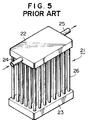
- a heat exchanger 21 comprises a pair of tanks 22 and 23.
- Inlet pipe 24 and outlet pipe 25 are connected to tank 22.
- a plurality of heat transfer tubes 26 (for example, refrigerant tubes) are fluidly connected between tanks 22 and 23.
- Each tube 26 has a central portion 26a and end portions 26b having diameters which are smaller than the diameter of central portion 26a. End portions 26b are inserted into holes 22a and 23a disposed in tanks 22 and 23, respectively, and fixed to tanks 22 and 23 by brazing.
- a partition 27 is provided in tank 22 at a center portion thereof.
- a heat medium for example, refrigerant, flows from inlet pipe 24 to outlet pipe 25 through the interior of tank 22, down heat transfer tubes 26, through the interior of tank 23, up heat transfer tubes 26 and through the interior of tank 22, as shown by arrows in Fig. 6.
- Fig. 7 depicts the structure of the connection between end portion 26b of each heat transfer tube 26 and tank 22 or 23.
- End portion 26b extends straight through tank 22 (23) and has a substantially uniform diameter which is smaller than the diameter of central portion 26a.
- End portion 26b is inserted through hole 22a (23a) and fixed to tank 22 (23) by brazing, welding, gluing or the like between the periphery of end portion 26b and the inner edge of hole 22a (23a).
- Gap A between the periphery of end portion 26b and the inner edge of hole 22a (23a) generally has a relatively small width, for example, not more than about 0.2 mm (0.008 in), so that a sufficiently thick layer of brazing material may be extended to uniformly cover end portion 26b.
- the width of gap A is also relatively small, for example, not more than about 0.2 mm (0.008 in). Specifically, if the width of gap A is greater than about 0.2 mm (0.008 in), it is difficult to provide a sufficient amount of brazing material in the gap to enable proper brazing to occur.
- end portions 26b as straight portions, however, presents difficulties in the manufacturing of the heat exchanger. Because the end portions 26b are straight and have a diameter which is only slightly less than the diameter of the holes, it is not easy to insert end portions 26b into holes 22a and 23a. Therefore, this type of heat transfer tube does not permit easy assembly of the heat exchanger.
- a heat transfer tube 31 comprises a central portion 31a and end portions 31b.
- Each end portion 31b is tapered from central portion 31a, so that the diameter of end portion 31b gradually decreases from a maximum diameter at a base 32 to a minimum diameter at a tip 33.
- the width of gap A between base 32 and the inner edge of hole 22a (23a) of tank 22 (23) is equal not more than about 0.2 mm (0.008 in).
- end portions 31b are tapered, they may be more easily inserted into holes 22a (23a). Therefore, this type of heat transfer tube permits easier assembly of the heat exchangers.
- straight end portions 26b are used, however, a wider variation in the length of tubes 26 may be allowed. Because the diameter of straight end portion 26b may be substantially uniform, the width of gap A is substantially constant as long as end portion 26b is disposed in hole 22a (23a).
- a heat exchanger comprises a pair of tanks spaced from each other and a plurality of substantially parallel heat transfer tubes fluidly connected between the pair of tanks.
- Each of the plurality of heat transfer tubes has a central portion having a central diameter and end portions inserted into respective holes disposed in the pair of tanks.
- the end portions each have a base diameter which is less than the diameter of a central portion of each heat transfer tube.
- At least one of the end portions of each heat transfer tube comprises a straight portion and a tapered portion.
- the straight portion extends straight from the central portion and has a base diameter which is the maximum diameter of the end portion.
- the diameter of the central portion may be substantially uniform throughout.
- the tapered portion extends from the straight portion with a tapering diameter which gradually decreases from the base diameter to a tip diameter at the tip of the end portion.
- the tip of the end portion of each heat transfer tube is inserted into one of the holes of one of the tanks. Because the tip of the tapered portion has a diameter less than the diameter of the hole of the tank, the insertion may be performed with ease. After the tube is inserted, the straight portion of the end portion is positioned in the hole.
- the straight portion has a diameter which is the maximum diameter of the end portion, and because the maximum diameter is predetermined so that the width of the gap between the periphery of the straight portion and the inner edge of the hole is a suitable distance for brazing therebetween, e.g., less than or equal to about 0.2 mm (0.008 in), even if the position of the end portion varies slightly in length, i.e., along the y-axis, the gap may still be maintained at a width suitable for brazing or otherwise connecting. Therefore, insertion of end portions of the heat transfer tubes is easily performed and a wider variation in the length of tubes is permitted while still providing suitable brazing width between the tubes and the holes of the tanks.
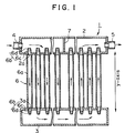
- Fig. 1 is a vertical cross-sectional view of a heat exchanger according to a first embodiment of the present invention.
- Fig. 2 is an enlarged, partial, vertical cross-sectional view of the heat exchanger depicted in Fig. 1.
- Fig. 3 is a perspective view of the heat exchanger depicted in Fig. 1.
- Fig. 4 is a vertical cross-sectional view of a heat exchanger according to a second embodiment of the present invention.
- Fig. 5 is a perspective view of a known heat exchanger.
- Fig. 6 is a vertical cross-sectional view of the heat exchanger depicted in Fig. 5.
- Fig. 7 is an enlarged, partial, vertical cross-sectional view of the heat exchanger depicted in Fig. 5.
- Fig. 8 is a partial vertical cross-sectional view of another conventional heat exchanger.
- Fig. 9 is a vertical cross-sectional view of the portion depicted in Fig. 8, showing a positioning of a tube.
- Heat exchanger 1 includes a pair of tanks 2 and 3. Inlet pipe 4 and outlet pipe 5 are connected to tank 2. A plurality of substantially parallel heat transfer tubes 6 (for example, refrigerant tubes) are fluidly connected between tanks 2 and 3. Heat transfer tubes 6 are arranged in columns and rows between tanks 2 and 3 of heat exchanger 1, as shown in Fig. 3. Each tube 6 has a central portion 6a and two end portions 6b having a maximum diameter less than the diameter of central portion 6a. The diameter of central portion 6a may be substantially uniform. A stepped portion 6e is formed between central portion 6a and each end portion 6b.
- Stepped portion 6e is substantially perpendicular to an axis through the diameter of both central portion 6a and a straight portion 6c.
- Central portion 6a and end portions 6b of each tube 6 each have circular cross-sections along the entire length of tube 6. End portions 6b are inserted into holes 2a and 3a defined on tanks 2 and 3, and fixed to the tanks by brazing.
- a partition 7 is provided in tank 2 at a central portion thereof. Holes 2a and 3a may have substantially equal diamaters.
- a heat medium, or example, refrigerant flows from inlet pipe 4 to outlet pipe 5 through the interior of tank 2, down heat transfer tubes 6, through the interior of tank 3, up heat transfer tubes 6, and through the interior of tank 2, as shown by arrows in Fig. 1. As the heat medium flows through tubes 6, heat is exchanged between the heat medium and the atmosphere or an air flow passing between tubes 6 via the walls of tubes 6.
- Fig. 2 depicts the structure of connection between end portion 6b of heat transfer tubes 6 and tank 2 or 3.
- End portions 6b have a base diameter which is a maximum diameter D less than a central diameter D1 of central portion 6a of each heat transfer tube 6.
- both end portions 6b of each heat transfer tube 6 comprises a straight portion 6c and a tapered portion 6d.
- Straight portion 6c extends straight out from the end of central portion 6a, that is, from stepped portion 6e, and has a diameter which is equal to the maximum diameter D.
- Tapered portion 6d extends from the end of straight portion 6c, i.e., base 41 to tip 40 of tube 6 with a diameter gradually decreasing from the maximum diameter D at base 41 to a tip diameter D3 at tip 40.
- end portion 6b is inserted into hole 2a (3a) defined on tank 2 (3), and straight portion 6c is positioned in hole 2a (3a).
- Each tube 6 is fixed to tanks 2 and 3 by brazing mainly at the positions of both straight portions 6c.
- end portion 6b of each heat transfer tube 6 is inserted into hole 2a (3a) of tank 2 (3) via tip 40 of tapered portion 6d. Because minimum diameter D3 at tip 40 of tapered portion 6d is less than the hole diameter D2 of hole 2a (3a), the insertion of the tube may be made with ease.
- straight portion 6c is positioned in hole 2a (3a). Because straight portion 6c has a diameter equal to the maximum diameter D, even if stepped portion 6e does not abut tank 2 (3) due to a slight variation in the length of tube 6, gap A may still be maintained at a suitable width for brazing or otherwise connecting.
- the width of gap A is predetermined to a suitable value for brazing, for example, less than about 0.2 mm (0.008 in).
- a brazing material may be provided to adequately extend over the periphery of straight portion 6c and the inner edge of hole 2a (3a) in gap A.
- effective brazing may be maintained.
- insertion of end portions 6b is easy, and effective brazing between the tubes 6 and the holes 2a and 3a of tanks 2 and 3 may be achieved in the manufacturing process of the heat exchanger.
- effective brazing may be obtained even if slight variations in the y-axis position of end portions 6b occur. This provides further improvement and uniformity in the quality of the heat exchanger.
- Fig. 4 depicts a heat exchanger according to a second embodiment of the present invention.
- straight portion 16c and tapered portion 16d are formed only on one end portion 16b of each heat transfer tube 16.
- the other end portion 16f of each tube 16 is formed merely as a straight pipe.
- end portions 16f are inserted into holes 3a of tank 3.
- end portions 16b are inserted into holes 2a of tank 2.
- end portions 16f are inserted into holes 3a, the end portions are easily inserted even if the end portions are straight. Nevertheless, if end portions 16b are also straight, the insertion thereof into holes 2a is difficult as aforementioned in the explanation of the related art.
- each end portion 16b has straight portion 16c and tapered portion 16d
- an easy insertion of each tube 16 may be achieved by tapered portion 16d, and excellent brazing between tube 16 and tank 2 may be ensured by straight portion 16c.
- straight portion 16c and tapered portion 16d are formed only on one end portion 16b of each heat transfer tube 16, effective brazing and easy manufacture are still obtained.
Landscapes
- Engineering & Computer Science (AREA)
- Physics & Mathematics (AREA)
- Thermal Sciences (AREA)
- Mechanical Engineering (AREA)
- General Engineering & Computer Science (AREA)
- Details Of Heat-Exchange And Heat-Transfer (AREA)
- Heat-Exchange Devices With Radiators And Conduit Assemblies (AREA)
Applications Claiming Priority (2)
| Application Number | Priority Date | Filing Date | Title |
|---|---|---|---|
| JP21876/93U | 1993-04-26 | ||
| JP021876U JPH0684188U (ja) | 1993-04-26 | 1993-04-26 | 熱交換器 |
Publications (2)
| Publication Number | Publication Date |
|---|---|
| EP0622601A1 true EP0622601A1 (de) | 1994-11-02 |
| EP0622601B1 EP0622601B1 (de) | 1997-01-29 |
Family
ID=12067333
Family Applications (1)
| Application Number | Title | Priority Date | Filing Date |
|---|---|---|---|
| EP94302824A Expired - Lifetime EP0622601B1 (de) | 1993-04-26 | 1994-04-20 | Wärmetauscher |
Country Status (5)
| Country | Link |
|---|---|
| US (1) | US5579834A (de) |
| EP (1) | EP0622601B1 (de) |
| JP (1) | JPH0684188U (de) |
| CN (1) | CN1100197A (de) |
| DE (1) | DE69401610T2 (de) |
Cited By (5)
| Publication number | Priority date | Publication date | Assignee | Title |
|---|---|---|---|---|
| FR2817334A1 (fr) * | 2000-11-27 | 2002-05-31 | Valeo Thermique Moteur Sa | Echangeur de chaleur brase, notamment pour vehicule automobile, et son procede de fabrication |
| EP1179723A3 (de) * | 2000-08-09 | 2003-03-26 | Deltacalor S.r.L. | Heizungsvorrichtung |
| EP1780491A1 (de) * | 2005-10-25 | 2007-05-02 | Zehnder Verkaufs- und Verwaltungs AG | Heizkörper, insbesondere Mehrsäuler-Heizkörper |
| EP2128537A3 (de) * | 2008-05-30 | 2013-09-25 | Viessmann Werke GmbH & Co. KG | Wärmetauscher |
| US9306361B2 (en) | 2011-06-01 | 2016-04-05 | Trumpf Laser- Und Systemtechnik Gmbh | Gas lasers including heat exchangers |
Families Citing this family (17)
| Publication number | Priority date | Publication date | Assignee | Title |
|---|---|---|---|---|
| JP3530660B2 (ja) * | 1995-12-14 | 2004-05-24 | サンデン株式会社 | 熱交換器のタンク構造 |
| FR2812718A1 (fr) * | 2000-08-04 | 2002-02-08 | Ciat Sa | Tube d'echange thermique et echangeur de chaleur intratubulaire muni de tels tubes |
| DE60100617T2 (de) | 2000-10-06 | 2004-06-09 | Visteon Global Technologies, Inc., Dearborn | Herstellung eines Rohres für einen Wärmetauscher |
| JP4109444B2 (ja) * | 2001-11-09 | 2008-07-02 | Gac株式会社 | 熱交換器およびその製造方法 |
| DE102004018317A1 (de) * | 2004-04-13 | 2005-11-03 | Behr Gmbh & Co. Kg | Wärmeübertrager für Kraftfahrzeuge |
| US10352484B2 (en) * | 2004-08-05 | 2019-07-16 | Faurecia Emissions Control Technologies Germany Gmbh | Exhaust system |
| EP1707912A1 (de) * | 2005-04-01 | 2006-10-04 | Fiwihex B.V. | Wärmetauscher und Gewächshaus |
| JP2006320910A (ja) * | 2005-05-17 | 2006-11-30 | Sanden Corp | 熱交換器用チューブおよびその製造方法 |
| NL1029280C1 (nl) * | 2005-06-17 | 2006-12-19 | Fiwihex B V | Behuizing met een koeling. |
| CA2635085A1 (en) | 2007-06-22 | 2008-12-22 | Johnson Controls Technology Company | Heat exchanger |
| WO2009148199A1 (en) * | 2008-06-03 | 2009-12-10 | Lg Electronics Inc. | Refrigerant system |
| JP6372332B2 (ja) * | 2014-12-08 | 2018-08-15 | 株式会社デンソー | 熱交換器及び熱交換器の製造方法 |
| US20170045309A1 (en) * | 2015-08-11 | 2017-02-16 | Hamilton Sundstrand Corporation | High temperature flow manifold |
| EP3760962B1 (de) * | 2019-07-05 | 2023-08-30 | UTC Aerospace Systems Wroclaw Sp. z o.o. | Wärmetauscher |
| WO2021068760A1 (zh) * | 2019-10-08 | 2021-04-15 | 杭州三花研究院有限公司 | 换热器 |
| IT201900019181A1 (it) * | 2019-10-17 | 2021-04-17 | Danieli Off Mecc | Tubo distributore per raffreddare nastri metallici |
| US12578145B2 (en) * | 2023-08-22 | 2026-03-17 | Hamilton Sundstrand Corporation | Heat exchanger core geometries used as support material and fluid connectivity passages for heat exchanger headering |
Citations (5)
| Publication number | Priority date | Publication date | Assignee | Title |
|---|---|---|---|---|
| FR2186637A1 (de) * | 1972-05-31 | 1974-01-11 | Raypak Inc | |
| JPS5956095A (ja) * | 1982-09-24 | 1984-03-31 | Nippon Radiator Co Ltd | 熱交換器に於ける合成樹脂製座板と金属管との接合方法 |
| EP0360362A1 (de) * | 1986-07-29 | 1990-03-28 | Showa Aluminum Kabushiki Kaisha | Kondensator |
| US5046555A (en) * | 1990-09-06 | 1991-09-10 | General Motors Corporation | Extended surface tube-to-header connection for condenser |
| EP0453738A1 (de) * | 1990-04-21 | 1991-10-30 | Behr GmbH & Co. | Wärmetauscher |
Family Cites Families (17)
| Publication number | Priority date | Publication date | Assignee | Title |
|---|---|---|---|---|
| US1561212A (en) * | 1924-07-16 | 1925-11-10 | Dempsey C Britton | Radiator |
| FR646612A (fr) * | 1927-12-31 | 1928-11-14 | économiseur consistant en bacs inférieur et supérieur reliés et ancrés par des tubes | |
| US1911375A (en) * | 1930-03-14 | 1933-05-30 | Babcock & Wilcox Co | Fluid heater and method of operating the same |
| US2158792A (en) * | 1934-12-07 | 1939-05-16 | Gen Refrigeration Corp | Header feed evaporator |
| US2225760A (en) * | 1938-05-09 | 1940-12-24 | Superheater Co Ltd | Return bend clamp block |
| DE803998C (de) * | 1948-10-12 | 1951-04-16 | Leo Hoppe | Anschluss der UEberhitzerrohre an den Dampfsammelkasten |
| FR1097396A (fr) * | 1953-11-06 | 1955-07-05 | Warme Austausch Technik G M B | échangeurs de chaleur |
| DE1143525B (de) * | 1958-01-15 | 1963-02-14 | Superheater Co Ltd | Zwischen dem Sammler oder Verteiler eines Waermeaustauschers und einem Rohr festgeschweisste Muffe |
| US3265126A (en) * | 1963-11-14 | 1966-08-09 | Borg Warner | Heat exchanger |
| GB1256228A (en) * | 1968-04-03 | 1971-12-08 | Ass Eng Ltd | Improvements in or relating to heat exchangers |
| DE1807464A1 (de) * | 1968-11-07 | 1970-06-11 | Gerhard Esser | Verfahren zur Herstellung von Radiatoren |
| GB1414473A (en) * | 1972-02-10 | 1975-11-19 | Covrad Ltd | Heat exchangers |
| US4153305A (en) * | 1978-03-02 | 1979-05-08 | Abex Corporation | Railroad air brake systems |
| FR2459534A1 (fr) * | 1979-06-14 | 1981-01-09 | Commissariat Energie Atomique | Procede et dispositif de fixation d'un tube de guidage d'un assemblage combustible nucleaire aux plaques d'extremites dudit assemblage |
| US4860823A (en) * | 1988-03-02 | 1989-08-29 | Diesel Kiki Co., Ltd. | Laminated heat exchanger |
| JPH0717965Y2 (ja) * | 1990-02-22 | 1995-04-26 | サンデン株式会社 | 熱交換器 |
| JPH04177094A (ja) * | 1990-11-13 | 1992-06-24 | Sanden Corp | 積層型熱交換器 |
-
1993
- 1993-04-26 JP JP021876U patent/JPH0684188U/ja active Pending
-
1994
- 1994-04-20 DE DE69401610T patent/DE69401610T2/de not_active Expired - Fee Related
- 1994-04-20 EP EP94302824A patent/EP0622601B1/de not_active Expired - Lifetime
- 1994-04-26 CN CN94106947.8A patent/CN1100197A/zh active Pending
-
1995
- 1995-08-28 US US08/520,275 patent/US5579834A/en not_active Expired - Fee Related
Patent Citations (5)
| Publication number | Priority date | Publication date | Assignee | Title |
|---|---|---|---|---|
| FR2186637A1 (de) * | 1972-05-31 | 1974-01-11 | Raypak Inc | |
| JPS5956095A (ja) * | 1982-09-24 | 1984-03-31 | Nippon Radiator Co Ltd | 熱交換器に於ける合成樹脂製座板と金属管との接合方法 |
| EP0360362A1 (de) * | 1986-07-29 | 1990-03-28 | Showa Aluminum Kabushiki Kaisha | Kondensator |
| EP0453738A1 (de) * | 1990-04-21 | 1991-10-30 | Behr GmbH & Co. | Wärmetauscher |
| US5046555A (en) * | 1990-09-06 | 1991-09-10 | General Motors Corporation | Extended surface tube-to-header connection for condenser |
Non-Patent Citations (1)
| Title |
|---|
| PATENT ABSTRACTS OF JAPAN vol. 008, no. 160 (M - 312) 25 July 1984 (1984-07-25) * |
Cited By (6)
| Publication number | Priority date | Publication date | Assignee | Title |
|---|---|---|---|---|
| EP1179723A3 (de) * | 2000-08-09 | 2003-03-26 | Deltacalor S.r.L. | Heizungsvorrichtung |
| FR2817334A1 (fr) * | 2000-11-27 | 2002-05-31 | Valeo Thermique Moteur Sa | Echangeur de chaleur brase, notamment pour vehicule automobile, et son procede de fabrication |
| EP1780491A1 (de) * | 2005-10-25 | 2007-05-02 | Zehnder Verkaufs- und Verwaltungs AG | Heizkörper, insbesondere Mehrsäuler-Heizkörper |
| EP2128537A3 (de) * | 2008-05-30 | 2013-09-25 | Viessmann Werke GmbH & Co. KG | Wärmetauscher |
| US9306361B2 (en) | 2011-06-01 | 2016-04-05 | Trumpf Laser- Und Systemtechnik Gmbh | Gas lasers including heat exchangers |
| EP2715886B1 (de) * | 2011-06-01 | 2017-08-02 | TRUMPF Laser-und Systemtechnik GmbH | Gaslaser mit einem wärmetauscher |
Also Published As
| Publication number | Publication date |
|---|---|
| CN1100197A (zh) | 1995-03-15 |
| DE69401610T2 (de) | 1997-06-12 |
| US5579834A (en) | 1996-12-03 |
| EP0622601B1 (de) | 1997-01-29 |
| DE69401610D1 (de) | 1997-03-13 |
| JPH0684188U (ja) | 1994-12-02 |
Similar Documents
| Publication | Publication Date | Title |
|---|---|---|
| EP0622601B1 (de) | Wärmetauscher | |
| US5842515A (en) | Heat exchanger and method of manufacturing header pipe for the same | |
| US5052478A (en) | Pipe for coolant condenser | |
| EP0641986B1 (de) | Wärmetauscher und Verfahren zu seiner Herstellung | |
| EP0703425B1 (de) | Plattenwärmeaustauscher | |
| KR100261006B1 (ko) | 열교환기용 편평튜우브 | |
| US5172762A (en) | Heat exchanger | |
| EP0745824B1 (de) | Wärmetauscher und Verfahren zu dessen Herstellung | |
| US5881456A (en) | Header tubes for heat exchangers and the methods used for their manufacture | |
| US5918667A (en) | Heat exchanger | |
| US5265672A (en) | Heat exchanger | |
| US5209292A (en) | Condenser header and tank assembly with interference fit baffle | |
| EP0846931B1 (de) | Befestigungsvorrichtung für Ölkühler und Verfahren zur Befestigung eines Ölkühlers | |
| GB2285858A (en) | A two-piece header | |
| US5467818A (en) | Heat exchanger | |
| US5782291A (en) | Heat exchanger | |
| US5562153A (en) | Heat exchanger and method of making heat exchangers | |
| US20070266730A1 (en) | Refrigerant Distributor and Method for Manufacturing the Same | |
| EP0802386B1 (de) | Rohrbündel-Wärmetauscher | |
| EP0798530A1 (de) | Wärmetauscher | |
| JP2001059692A (ja) | 熱交換器用パイプと、熱交換器用パイプとチューブとの連結構造 | |
| JPH1047888A (ja) | 熱交換器 | |
| EP0805331A2 (de) | Multiröhren-Wärmetauscher | |
| EP1167897B1 (de) | Verflüssiger | |
| JPH08240395A (ja) | 熱交換器 |
Legal Events
| Date | Code | Title | Description |
|---|---|---|---|
| PUAI | Public reference made under article 153(3) epc to a published international application that has entered the european phase |
Free format text: ORIGINAL CODE: 0009012 |
|
| AK | Designated contracting states |
Kind code of ref document: A1 Designated state(s): DE FR GB IT SE |
|
| 17P | Request for examination filed |
Effective date: 19950412 |
|
| 17Q | First examination report despatched |
Effective date: 19951208 |
|
| GRAG | Despatch of communication of intention to grant |
Free format text: ORIGINAL CODE: EPIDOS AGRA |
|
| GRAH | Despatch of communication of intention to grant a patent |
Free format text: ORIGINAL CODE: EPIDOS IGRA |
|
| GRAH | Despatch of communication of intention to grant a patent |
Free format text: ORIGINAL CODE: EPIDOS IGRA |
|
| GRAA | (expected) grant |
Free format text: ORIGINAL CODE: 0009210 |
|
| AK | Designated contracting states |
Kind code of ref document: B1 Designated state(s): DE FR GB IT SE |
|
| ET | Fr: translation filed | ||
| REF | Corresponds to: |
Ref document number: 69401610 Country of ref document: DE Date of ref document: 19970313 |
|
| ITF | It: translation for a ep patent filed | ||
| PLBE | No opposition filed within time limit |
Free format text: ORIGINAL CODE: 0009261 |
|
| STAA | Information on the status of an ep patent application or granted ep patent |
Free format text: STATUS: NO OPPOSITION FILED WITHIN TIME LIMIT |
|
| 26N | No opposition filed | ||
| PGFP | Annual fee paid to national office [announced via postgrant information from national office to epo] |
Ref country code: SE Payment date: 20000406 Year of fee payment: 7 |
|
| PGFP | Annual fee paid to national office [announced via postgrant information from national office to epo] |
Ref country code: FR Payment date: 20000411 Year of fee payment: 7 |
|
| PGFP | Annual fee paid to national office [announced via postgrant information from national office to epo] |
Ref country code: DE Payment date: 20000417 Year of fee payment: 7 |
|
| PGFP | Annual fee paid to national office [announced via postgrant information from national office to epo] |
Ref country code: GB Payment date: 20000419 Year of fee payment: 7 |
|
| PG25 | Lapsed in a contracting state [announced via postgrant information from national office to epo] |
Ref country code: GB Free format text: LAPSE BECAUSE OF NON-PAYMENT OF DUE FEES Effective date: 20010420 |
|
| PG25 | Lapsed in a contracting state [announced via postgrant information from national office to epo] |
Ref country code: SE Free format text: LAPSE BECAUSE OF NON-PAYMENT OF DUE FEES Effective date: 20010421 |
|
| PG25 | Lapsed in a contracting state [announced via postgrant information from national office to epo] |
Ref country code: FR Free format text: THE PATENT HAS BEEN ANNULLED BY A DECISION OF A NATIONAL AUTHORITY Effective date: 20010430 |
|
| EUG | Se: european patent has lapsed |
Ref document number: 94302824.1 |
|
| GBPC | Gb: european patent ceased through non-payment of renewal fee |
Effective date: 20010420 |
|
| PG25 | Lapsed in a contracting state [announced via postgrant information from national office to epo] |
Ref country code: DE Free format text: LAPSE BECAUSE OF NON-PAYMENT OF DUE FEES Effective date: 20020201 |
|
| REG | Reference to a national code |
Ref country code: FR Ref legal event code: ST |
|
| PG25 | Lapsed in a contracting state [announced via postgrant information from national office to epo] |
Ref country code: IT Free format text: LAPSE BECAUSE OF NON-PAYMENT OF DUE FEES;WARNING: LAPSES OF ITALIAN PATENTS WITH EFFECTIVE DATE BEFORE 2007 MAY HAVE OCCURRED AT ANY TIME BEFORE 2007. THE CORRECT EFFECTIVE DATE MAY BE DIFFERENT FROM THE ONE RECORDED. Effective date: 20050420 |