EP0622694B1 - Système de mise en boîte postale et de tri pour alimenter des feuilles depuis un dispositif de sortie vers des casiers à courrier verrouillables - Google Patents
Système de mise en boîte postale et de tri pour alimenter des feuilles depuis un dispositif de sortie vers des casiers à courrier verrouillables Download PDFInfo
- Publication number
- EP0622694B1 EP0622694B1 EP19940303030 EP94303030A EP0622694B1 EP 0622694 B1 EP0622694 B1 EP 0622694B1 EP 19940303030 EP19940303030 EP 19940303030 EP 94303030 A EP94303030 A EP 94303030A EP 0622694 B1 EP0622694 B1 EP 0622694B1
- Authority
- EP
- European Patent Office
- Prior art keywords
- bin
- mailbox
- bins
- user
- sheets
- Prior art date
- Legal status (The legal status is an assumption and is not a legal conclusion. Google has not performed a legal analysis and makes no representation as to the accuracy of the status listed.)
- Expired - Lifetime
Links
- 230000007246 mechanism Effects 0.000 claims description 18
- 230000004044 response Effects 0.000 claims description 5
- 238000011144 upstream manufacturing Methods 0.000 claims description 2
- 230000032258 transport Effects 0.000 description 17
- 230000006870 function Effects 0.000 description 11
- 230000003287 optical effect Effects 0.000 description 5
- 238000003860 storage Methods 0.000 description 5
- 230000000007 visual effect Effects 0.000 description 5
- 230000005540 biological transmission Effects 0.000 description 4
- 238000009826 distribution Methods 0.000 description 4
- 238000012986 modification Methods 0.000 description 4
- 230000004048 modification Effects 0.000 description 4
- 230000009977 dual effect Effects 0.000 description 3
- 238000003780 insertion Methods 0.000 description 3
- 230000037431 insertion Effects 0.000 description 3
- 238000010926 purge Methods 0.000 description 3
- UIQMVEYFGZJHCZ-SSTWWWIQSA-N Nalorphine Chemical compound C([C@@H](N(CC1)CC=C)[C@@H]2C=C[C@@H]3O)C4=CC=C(O)C5=C4[C@@]21[C@H]3O5 UIQMVEYFGZJHCZ-SSTWWWIQSA-N 0.000 description 2
- 235000010724 Wisteria floribunda Nutrition 0.000 description 2
- 238000004891 communication Methods 0.000 description 2
- 238000001514 detection method Methods 0.000 description 2
- 238000010586 diagram Methods 0.000 description 2
- 230000006872 improvement Effects 0.000 description 2
- 238000012545 processing Methods 0.000 description 2
- 238000004080 punching Methods 0.000 description 2
- 238000000926 separation method Methods 0.000 description 2
- 230000011664 signaling Effects 0.000 description 2
- 230000002159 abnormal effect Effects 0.000 description 1
- 230000008901 benefit Effects 0.000 description 1
- 230000008859 change Effects 0.000 description 1
- 230000001934 delay Effects 0.000 description 1
- 230000000694 effects Effects 0.000 description 1
- 230000005484 gravity Effects 0.000 description 1
- 230000003760 hair shine Effects 0.000 description 1
- 230000002452 interceptive effect Effects 0.000 description 1
- 239000004973 liquid crystal related substance Substances 0.000 description 1
- 238000000034 method Methods 0.000 description 1
- 239000000203 mixture Substances 0.000 description 1
- 238000012544 monitoring process Methods 0.000 description 1
Images







Classifications
-
- G—PHYSICS
- G03—PHOTOGRAPHY; CINEMATOGRAPHY; ANALOGOUS TECHNIQUES USING WAVES OTHER THAN OPTICAL WAVES; ELECTROGRAPHY; HOLOGRAPHY
- G03G—ELECTROGRAPHY; ELECTROPHOTOGRAPHY; MAGNETOGRAPHY
- G03G15/00—Apparatus for electrographic processes using a charge pattern
- G03G15/65—Apparatus which relate to the handling of copy material
- G03G15/6538—Devices for collating sheet copy material, e.g. sorters, control, copies in staples form
-
- G—PHYSICS
- G03—PHOTOGRAPHY; CINEMATOGRAPHY; ANALOGOUS TECHNIQUES USING WAVES OTHER THAN OPTICAL WAVES; ELECTROGRAPHY; HOLOGRAPHY
- G03G—ELECTROGRAPHY; ELECTROPHOTOGRAPHY; MAGNETOGRAPHY
- G03G15/00—Apparatus for electrographic processes using a charge pattern
- G03G15/50—Machine control of apparatus for electrographic processes using a charge pattern, e.g. regulating differents parts of the machine, multimode copiers, microprocessor control
- G03G15/5016—User-machine interface; Display panels; Control console
-
- G—PHYSICS
- G03—PHOTOGRAPHY; CINEMATOGRAPHY; ANALOGOUS TECHNIQUES USING WAVES OTHER THAN OPTICAL WAVES; ELECTROGRAPHY; HOLOGRAPHY
- G03G—ELECTROGRAPHY; ELECTROPHOTOGRAPHY; MAGNETOGRAPHY
- G03G15/00—Apparatus for electrographic processes using a charge pattern
- G03G15/50—Machine control of apparatus for electrographic processes using a charge pattern, e.g. regulating differents parts of the machine, multimode copiers, microprocessor control
- G03G15/5075—Remote control machines, e.g. by a host
- G03G15/5087—Remote control machines, e.g. by a host for receiving image data
-
- G—PHYSICS
- G03—PHOTOGRAPHY; CINEMATOGRAPHY; ANALOGOUS TECHNIQUES USING WAVES OTHER THAN OPTICAL WAVES; ELECTROGRAPHY; HOLOGRAPHY
- G03G—ELECTROGRAPHY; ELECTROPHOTOGRAPHY; MAGNETOGRAPHY
- G03G15/00—Apparatus for electrographic processes using a charge pattern
- G03G15/50—Machine control of apparatus for electrographic processes using a charge pattern, e.g. regulating differents parts of the machine, multimode copiers, microprocessor control
- G03G15/5075—Remote control machines, e.g. by a host
- G03G15/5091—Remote control machines, e.g. by a host for user-identification or authorisation
-
- G—PHYSICS
- G03—PHOTOGRAPHY; CINEMATOGRAPHY; ANALOGOUS TECHNIQUES USING WAVES OTHER THAN OPTICAL WAVES; ELECTROGRAPHY; HOLOGRAPHY
- G03G—ELECTROGRAPHY; ELECTROPHOTOGRAPHY; MAGNETOGRAPHY
- G03G21/00—Arrangements not provided for by groups G03G13/00 - G03G19/00, e.g. cleaning, elimination of residual charge
- G03G21/04—Preventing copies being made of an original
-
- G—PHYSICS
- G03—PHOTOGRAPHY; CINEMATOGRAPHY; ANALOGOUS TECHNIQUES USING WAVES OTHER THAN OPTICAL WAVES; ELECTROGRAPHY; HOLOGRAPHY
- G03G—ELECTROGRAPHY; ELECTROPHOTOGRAPHY; MAGNETOGRAPHY
- G03G2215/00—Apparatus for electrophotographic processes
- G03G2215/00025—Machine control, e.g. regulating different parts of the machine
- G03G2215/00109—Remote control of apparatus, e.g. by a host
-
- G—PHYSICS
- G03—PHOTOGRAPHY; CINEMATOGRAPHY; ANALOGOUS TECHNIQUES USING WAVES OTHER THAN OPTICAL WAVES; ELECTROGRAPHY; HOLOGRAPHY
- G03G—ELECTROGRAPHY; ELECTROPHOTOGRAPHY; MAGNETOGRAPHY
- G03G2215/00—Apparatus for electrophotographic processes
- G03G2215/00362—Apparatus for electrophotographic processes relating to the copy medium handling
- G03G2215/00789—Adding properties or qualities to the copy medium
- G03G2215/00822—Binder, e.g. glueing device
- G03G2215/00827—Stapler
-
- G—PHYSICS
- G03—PHOTOGRAPHY; CINEMATOGRAPHY; ANALOGOUS TECHNIQUES USING WAVES OTHER THAN OPTICAL WAVES; ELECTROGRAPHY; HOLOGRAPHY
- G03G—ELECTROGRAPHY; ELECTROPHOTOGRAPHY; MAGNETOGRAPHY
- G03G2215/00—Apparatus for electrophotographic processes
- G03G2215/00362—Apparatus for electrophotographic processes relating to the copy medium handling
- G03G2215/00886—Sorting or discharging
- G03G2215/00907—Electronically addressable mailing bins
-
- G—PHYSICS
- G03—PHOTOGRAPHY; CINEMATOGRAPHY; ANALOGOUS TECHNIQUES USING WAVES OTHER THAN OPTICAL WAVES; ELECTROGRAPHY; HOLOGRAPHY
- G03G—ELECTROGRAPHY; ELECTROPHOTOGRAPHY; MAGNETOGRAPHY
- G03G2215/00—Apparatus for electrophotographic processes
- G03G2215/00362—Apparatus for electrophotographic processes relating to the copy medium handling
- G03G2215/00919—Special copy medium handling apparatus
- G03G2215/00932—Security copies
Definitions
- the present invention relates to a mailboxing system and sorter for feeding sheets from an output device, such as a printer, into selected mailbox bins. More particularly the system provides a means for locking and unlocking one or more of the selected mailbox bins.
- US Defensive Publication T 102 102 discloses bins positioned at a copier output which are locked to the user by means of a badge reader or the like. The user enters identification data into the copier to enable the copier to operate.
- US-A 4, 437,660 describes a scanning mechanism for scanning individual output bins for receiving documents from a paper printer. The mechanism determines each bin's availability for receiving documents, the degree of fullness and whether or not a lock box is positioned in the bin for receiving designated documents.
- US-A- 4,470,356 describes a lockbox for a word processor printer output bin attached to a printer.
- the lockbox which is insertable and removable from the output bin, is locked in the bin upon insertion, and can only be removed by disengagement of a first locking means.
- the lockbox has a security door which is positioned in a paper receiving position upon insertion into the output bin and which must be closed in order to remove the lockbox from the output bin.
- EP-A-241 273 describes a sheet handling apparatus with means for locking a selected bin to receive the sheets therein so as to prevent access to the sheets received in the selected bin by unauthorized individuals.
- JP-A-63138883 describes a facsimile machine provided with a stacker having a plurality of drawers into which sheets are fed.
- the stacker is provided with a lock mechanism which locks a drawer associated with a user until the user inserts an ID card into a card reader.
- the present invention provides a system, a sorter and an electronic printer and multibin mailbox system in accordance with the claims appended hereto.
- a mailboxing system for feeding sheets from an output device into a mailbox bin selected from a plurality of mailbox bins disposed in a housing with at least some slidably supported therein, the system including control means for controlling sheet feeding means to feed the sheets from the output device into the selected mailbox bin, the sheet feeding means including a plurality of diverter gates, each diverter gate being associated with a respective mailbox bin, each diverter gate being individually movable from a first position, permitting sheets to travel past its associated bin, to a second position for directing the sheets into its associated bin, and including actuator means for selectively moving one of the diverter gates to the second position, locking means operable by said control means for restricting access to sheets stacked in the selected mailbox bin and release means operable to release the locking means for providing access to the stacked sheets in the selected bin, the locking means serving to lock the mailbox bins in the housing to prevent sliding movement of a mailbox bin whilst sheets are still being fed into that mailbox bin and the release means serving to unlock the mailbox bins to
- the release means is operable to release the locking means for the selected mailbox bin while one or more or all of the remainder of the mailbox bins remain locked.
- the mailbox bins are disposed in a housing and are slidably supported therein, the locking means serving to lock the mailbox bins in the housing to prevent sliding movement and the release means serving to unlock the mailbox bins to permit sliding movement and to allow at least partial removal of the mailbox bins from the housing.
- the mailbox bins are spring-loaded so as to automatically slide out like drawers from the housing when released by a latching mechanism, the latching mechanism being conveniently operated by electromagnetic means such as a solenoid.
- a spring-loaded bin door pivotally opens by spring force when a solenoid escapement latch or the like is released by the solenoid receiving an electrical unlocking signal from the control means.
- a system for separating the outputted plural jobs of plural physical sheets from the output of an electronically shared users job output device by separate designated recipients of document jobs electronically transmitted to the output device comprising an output sorting mailbox system, said sorting mailbox system including a sheet input path at said output of said shared users output device to sequentially receive said output job sheets therefrom, plural discrete job output sheet collection bins providing user mailboxes, a control system for electronically assigning discrete bin numbers to respective said output sheet collection bins, and for electronically assigning said discrete bin numbers to different said users of said shared users job printer, a sheet bin selection and feeding system controlled by said control system for selectively feeding said job sheets from said sheet input path to designated output sheet collection bins corresponding to said electronically assigned bin numbers for said designated users, said output sorting mailbox system also having a bin locking system for restricting access to a plurality of individual said output sheet collection user mailbox bins thereof, including an electrical bin unlocking system operatively connecting with said control system for automatically unlocking discrete said bins in
- said sheet feeding means includes a deflector at each tray normally permitting travel of a sheet past the trays, each said deflector being individually shiftable to a position to direct a sheet into a selected tray, and including actuator means for selectively shifting one of said deflectors to said said position directing a sheet to a tray.
- An embodiment herein provides convenient discrete locked bins security for received hard copies for several different job recipients of shared user printers. That is, also disclosed in the example hereinbelow is electronically controlled bin unlocking for private bins security. These are more accurately described herein as "privacy doors" for certain designated bins. This allows plural recipients to share the same printer or the like receiver, without disclosing, compromising or commingling their separate jobs and/or correspondence.
- the disclosed embodiment provides a stand-alone "mailbox” or addressable sorter which can automatically sort and file various conventional output documents (conventional "hard copies", i.e., physical sheets) in discrete designated bins, which can optionally be secured.
- these locked bins can be easily individually unlocked electrically to provide almost instant access to the secured hard copies.
- users or recipients do not need to stand by printers awaiting outputs to avoid their being read, or even accidentally taken, by other users, or commingled together into one stacking tray.
- emailboxing refers to handling or sorting physical, i.e., "hard copy” printed sheets. It does not refer to electronic documents or images, which are much easier to manipulate.
- a "mailbox" in the example herein takes multiple print jobs from a printer (from user terminals, fax, networked purge images, scanned document jobs, or the like or combinations thereof) and separates jobs by users and stacks these hardcopy outputted print jobs into individual bins for individual users, by users.
- users may also send print jobs to other users' mailbox bins if desired.
- Mailbox bins can, in general, be either user assignable, or automatically assigned by the printer, print server, or mailbox unit.
- jobs can be individually stapled if a stapler unit is provided.
- Optional security doors can be added to any or all bins if desired.
- An overflow bin or general, shared, stacking tray may also desirably be provided, not assigned to any one user.
- Mailboxing may more specifically, as in the example herein, refer to temporarily or permanently assigning a unique and predetermined electronic address to respective ones of plural bins of sorter-like equipment for a copier, printer or facsimile machine output, and enabling a particular user's output of one or more jobs to be directed into one or more selected bins so assigned. It may or may not include means for locking the bins and unlocking access thereto, as indicated above and as in the example herein.
- each bin has an associated LCD or other type of display with the appropriate user name or label displayed, and/or a common or central display, as in the example herein, and/or wherein jobs are placed in more than one available bin if needed, i.e, if the sheet stacking capacity of one assigned bin is exceeded.
- a mailbox for a laser or other electronic page input printer may desirably print and feed plural pre collated sets of sheets into a selected bin, rather than functioning as a normal collator or sorter, [although it may do so additionally or alternatively] since an electronic page printer can normally easily electronically reorder and recirculate the "original" pages being copied to "copy” and output them in precollated or serial page job set order, rather than making plural directly sequential copies of each page requiring post-collation and separate bins for each copy set in a sorter or collator.
- a very desirable mailbox system feature is a "variable bin assignment" system in which many users can share one mailbox unit with only a limited number of bins by variable (dynamic) bin assignments and their electronic logging or tracking, with the bin assignment(s) for a particular user or group of users, depending on bin availability (the bins empty at any given time) rather than a fixed, permanent assignment of certain bins to certain users or customers. This greatly increases the effective capacity or the number of potential shared users.
- a sheet output mailboxing system for selectively collecting the sheets outputted by a shared users printer in an arrayed plurality of mailbox bins of a limited sheet capacity per bin, for collecting such output sheets therein in collated printer job sets of stacked plural said output sheets per job, and with sheet feeding means for sequentially feeding said output sheets from said printer to said mailbox bins so as to be segregated by bins by respective users of said shared user printer, the improvement wherein the mailbox bins are not permanently assigned to particular users, and are variably assigned, comprising a variable bin selector for selectably collecting plural said collated job sets of said shared printer output sheets in a selected bin of said array of mailbox bins; said variable bin selector providing for stacking a limited number of subsequent job sets from the same printer user on top of prior job sets in the same said selected mailbox bin; an electronic controller for controlling said variable bin selector for repeatedly variably selecting which ones of said plurality of mailbox bins will be temporarily assigned to particular said shared printer users; said controller collecting information as to which said
- Another very desirable and related "mailbox" feature is a "virtual bin” concept, in which the software in a programmed computer or controller controlling the mailbox sheet distributor puts the first job output of user A into an assigned bin X which is determined to be available. Then, if a subsequent job for user A will also fit into bin X, it is also put into bin X. If not, then the subsequent job for user A is automatically put into an assigned "overflow" bin Y, etc.. I.e., for each user, the number of assigned bins is automatically increased to meet the users need. Preferably, adjacent bins are used for the job overflow.
- Art noted re bin overflow features in general includes Xerox Corporation US-A-3,871,643 issued March 18, 1975 to W.
- Another very desirable feature is to use "mailbox" bins to store plural (more than one) bound (e.g. stapled) sets in a selected assigned one or more mailbox bins (i.e. so that any particular user-designated bin can store plural stapled sets from the same or different jobs).
- "mailbox" bins to store plural (more than one) bound (e.g. stapled) sets in a selected assigned one or more mailbox bins (i.e. so that any particular user-designated bin can store plural stapled sets from the same or different jobs).
- Another desirable "mailbox” feature is to provide a modular integral unit for improved handling and organizing the sequential sheets output of a wide variety of printers, copiers and/or facsimile machines or combinations or multifunction "combo" units thereof, especially shared user and/or electronically connected interoffice "system” printer units.
- Another optional feature is to provide a modular finishing/mailboxing device optionally enabling eithe rleft or right printer exit commonality. I.e., the ability to accept squential sheet output from either right-exit or left-exit printers. Art relative thereto is discussed below.
- Another optional feature is to use part of the sheet input transport path or an interconnect module as a sheet inverter or rotator.
- Sheet rotators per se are well known, and need not be disclosed in detail herein. See for example, Xerox Corporation US-A-5,090,638] It may also optionally use the back side of a sorter-type vertical sheet transport belt to bring documents from the printer into the finisher.
- Other options can include providing enhanced job set finishing functions. For example, stapling and/or other binding, punching, folding, special sheet inserts or booklet making, and mailbox sorting of either the finished or unfinished sets.
- Another desirable feature is a bin assignment display system wherein the mailbox unit has a central (or bin-associated) LCD or other such bin-identifying operator display, and wherein user's jobs are placed in one, or (if needed) multiple, available bins, with all the appropriate bin(s) identified and displayed for the user name or other identifier, which may also be displayed
- a separate "gathering tray” may be provided for combining job outputs, in the order they were generated, from some or all of the assigned bins, removing the jobs from the bins and outputting them in a single stack.
- the term “virtual bin” as used herein refers to one aspect of the "dynamic bin assignment” system taught herein, whereby assignment of additional bins for the same user can be automatically provided if the sheet capacity of one bin will be exceeded. This should not be confused with a different use of the term “virtual bin” to refer to systems in which jobs in various bins are automatically unloaded from the bins onto a common separate stack.
- Another option is a system of bin coding and distribution in which a designated user pin code number and the number of pages associated with the user's job are printed and sent on a job cover sheet read by a bin code reader and gated distributor in the mailbox sorter unit.
- the present system is desirably usable for electronic mail hardcopy prints and/or other networked or shared user document prints in general.
- the printer can electronically recognize the sender or user terminal sending the printing job from network or document electronic information already available in said job. (Such shared printers may also have alternate scanner or floppy disk document inputs.)
- the designated printer or printers and addressees may be changed or forwarded by an intermediate terminal and/or programmed software, which here can be used to change the bin addresses.
- the job or cover sheet may contain additional encoded information for other copy or distribution controls.
- Canon Takahashi et al. US-A-4,051,419, issued February 26, 1985 and filed August 20, 1981, is of particular interest for its random bin access and an early teaching of collating paper output of either a laser printer or a copier with automatic bin input switching from detected full bins to bins from which the papers have been removed, for maximizing bins utilization and minimizing printing delays.
- the operation described is that for sorting (collating) not mailboxing of collated job sets.
- the bin and sheet path sensors described there (and elsewhere) may be used herewith, if desired. This same reference also teaches bin indicator displays.
- US-A-4,691,914 discloses a random plural bin access [with plural solenoids] sheet receiver. It discloses sheet input from both the right or left sides, indicated as from a copier and a printer respectively.
- US-A-4,830,358 refers to "mailbox" sorters merely in citing a prior US-A-4,288,070 to Fred R. Lagner [which does not itself discuss that] in Col. 1, lines 29-31. Said US-A-4,830,358 also says in Col. 1 line 44 that it provides a sorter in which the trays may be "randomly accessed", and discusses that further re a printer connection in at least Col. 11. Col. 8 bottom to Col. 9 top, et al.. This US-A-4,830,358 patent further discloses printer/sorter command signals and controls.
- a modular unit sorter is generally indicated in Col. 1 to be for sharing a printer with a plurality of users, sorting and compiling copies by user. It claims an output sorter having fixed trays and a pivotable sorter guide member for directing copy sheets to a sorter tray. Each tray may also have a gate mechanism for retaining sheets in the tray. It is suggested in Col. 6 that a mailbox can be assigned or dedicated to each user, and used as a "mailbox" by entering an ID code and printing data.
- This reference is also of interest re detecting the fullness of a sorter bin and for delivering copy sheets to the next available sorter bin.
- I.e., also disclosed in said US-A-5,141,222 reference Col. 8 are means for detecting the fullness [reaching of sheet stacking capacity] of a tray and incrementing this sorter tray copy sheet guide to another (empty) sorter tray.
- Canon US-A-4,501,419 issued February 26, 1985 to Y. Takahashi, et al.
- Printer products noted with integral open sorter bins include the Canon NP-9030 sold for several years with a sorter option; the Kyocera F-2010 and F-3010 laser printers with their 5 bin sorter option (since 1988?); and Océ van der Grinten Corporation's recently commercially displayed "6750" and "6800" printers configurable with either 20 or 40 bin optional programmable sorter/mailboxes.
- Toshiba and its OEM Genicon recently announced a 10 bin "mailbox sorter" for their network printers, supported by a Windows driver. The Toshiba user selects a bin number from the driver menu (not the network). Thus, users all have to agree among themselves who gets what bins.
- the Genicon system allows the network administrator to assign bins.
- a desirable additional feature for mailboxing systems is to staple or otherwise bind, fasten or finish the sheets of each job together, so that plural finished sets are removable as such from the user's bin(s), maintained neatly stacked and separated from other jobs by being fastened. This can be done by pre-compiling and stapling sets before they are placed into mailbox bins, as in the above-cited US-A-5,098,074 to the same B. Mandel, et al..
- Prior art on lockable and unlockable copier or printer bins or mail boxes for the output sheets thereof includes the above-cited EPO application No. 0 241 273, dislcosing a reproducing machine with lockable and unlockable bins which can be selected by the user for receiving copy sheets, precollated or uncollated. It teaches alternatively remote user or laser printer input, with copy bin lock boxes, and central computer display bin electrical bin unlocking entry and control usable herewith. Further as to bin locking, US-A-4,470,356 entitled “Word Processor-Controlled Printer Output Bin Lock Box", issued September 11, 1984, to Datapoint Corp., by D. Davis, et al., discloses a lockbox insertable and removable from an output bin.
- U.S. Defensive Publication No. T102,102 entitled “Access Controlled Copier” Published August 3, 1982 by Albert Bolle, et. al. discloses sorter bins which can be locked to the user by means of a badge reader or the like.
- the user-entered identification data is entered and recorded on the first copy which is delivered to the locked sorter bin or bins.
- IBM Corp. US-A-4,414,579 entitled "Information Transmitting and Receiving Station Utilizing a Copier-Printer" issued November 8, 1983 discloses a secured mailbox located at the bottom of the collator.
- Xerox Corporation reportedly provided modified copier sorters with locked bins for at least the U.S. State Department many years ago.
- art relating to sorter bin assignment schemes wherein the bins have an associated LCD or the like type of visual display includes US-A-3,905,594 to Davis; and the above-noted US-A-4,437,660 to Tomkins et al; US-A-4,501,419 to Takahashi, et al.; and U.S. Defensive Publication T102,102 to Bolle et al.. Also, Fuji Xerox Corp. FX-10475 Japanese Application No. S 59-55424, filed April 17, 1984 and published on November 6, 1985 as Kokai No. 60-167054.
- the mailbox unit has an input which adapts or adjusts to various printer output levels, or an interface unit or interconnect transport may be provided in a known manner to sequentially feed the printer output sheets from the printer into the sheet input entrance of the mailbox unit.
- the illustrated mailbox bins, compiler, stapler, etc. illustrated or described herein are exemplary, and may vary considerably.
- the general reference number 10 will be utilized below for the mailbox unit or module, even though modifications thereof are variously shown herein. Likewise, the general reference number 11 will be used throughout for an individual mailbox (bin).
- the disclosed systems provide for stacking the sheets sequentially outputted from the printer in separate job sets into one or more temporarily and variably assigned "mailboxes" of a "mailboxing" job sorting accessory unit having a number of variably assignable "mailbox” bins.
- a dynamic "mailboxing" unit and system for dynamically separating into mailboxes by currently assigned users the sheet outputs of various users of a shared users printer (including facsimile receivers or combination units).
- a variable display indicates the bins into which that particular user's jobs have been placed last and not yet removed. These may be plural pre-compiled and/or pre-stapled job sets all stacked in one bin.
- the exemplary disclosed system may also provide a bypass for sequentially stacking unstapled user sheets directly in a mailbox without compiling and stapling. Also disclosed is automatic overflow assignments of additional temporarily designated bins for identified users, as needed, to provide effectively unlimited or "virtual bin” plural job stacking.
- An integral moving sheet deflector, compiler and stapler unit is shown for collecting, compiling, and optionally stapling, and ejecting job sets of sheets for separate designated users into one or more of these discrete but variably assigned "mailboxes".
- the disclosed "mailboxing" units may also have "privacy doors” locking for restricting access to at least some of the mailbox bins, with electrical door unlocking of selected bins in response to entry of a user access code, and other user features.
- a shared user printer output job can be generated and get to a mailbox unit from various sources.
- customers can send a job to a printer from their respective workstations, e.g., from a screen display menu or job ticket, as further discussed herein.
- Another potential job source is a facsimile document or message addressed or directed to that printer, preferably with a designated recipient's mailbox or other user code number sent with the fax message.
- the print server or mailbox unit can also then send an acknowledgement message to the designated recipient's workstation noting that the fax has been received in that user's mailbox. That is, the fax sender could enter a code from their fax transmitter (a fax unit or computer terminal), using, e.g., the number keypad, that would indicate to the receiving printer and its mailbox unit who the recipient is.
- the mailbox unit would then automatically put the printer fax job in the correct (assigned) bin.
- the phone modem (of the workstation, printer, server, or mailbox unit) could then call the designated recipient to send a recorded message saying that they have a fax. (If no such designator code is specified, the fax can go to an unlocked general use bin.) It has been suggested that since the CCITT G3 Standard for DIS/DCS FAX transmission signals has a 20 digit field for the send phone number, and only 10 digits thereof are normally needed for internal U.S. transmissions, that these normally inused field places could be used to send a known "mailbox" bin code number as part of the initial FAX transmission, for automatic feeding of that received FAX transmission to that designated bin of a fax receiver which is provided with plural output "mailbox" bins.
- a print job can also be sent to another person's mailbox bin directly, without going to their workstation. For example, someone might want to send hardcopies of a contract that needs to be signed to other system users. Rather than just electronically mailing each of them an electronic copy, a print order with their mailbox designators can also or alternatively be sent to the printer for printing so that hardcopy is immediately printed and placed in mailbox bins assigned to them, as described herein.
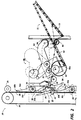
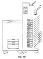
- a stand-alone printer output "mailbox" job sorting unit 10 with plural bins 11, and an integrated job compiler finisher unit, such as 90, by way of examples thereof.
- the conventionally sequentially received hard copy of plural page documents from a pre-collation output electronic printer or the like is fed into the mailbox unit 10 and automatically controlled for the particular bin 11 assignment destination of the job sheets.
- the mailbox unit 10 directs all designated sheets of a users job to available bin or bins 11 temporarily assigned to that printer user based in availability.
- the disclosed mailbox unit 10 can be a universal or dedicated stand-alone unit that is attached to, or even simply moved next to, the output of almost any conventional printer.
- Plural units 10 may be ganged in series like plural sorters, if desired, for increased numbers of bins, using conventional sheet pass-through feeders and gates.
- sorter bin units can be extended or serially connected in this manner to provide more available bins, if desired.
- the job sorting unit 10 can take sheets inputted at one or more sheet inputs 20 from various printer outputs, including multi-functional units.
- the input 20 may, if desired, be provided with a pivotal or otherwise vertically adjustable input ramp and/or feeder, which may be in an interface module, to align with various levels of printer outputs.
- Left and right side sheet inputs may be adapted to operatively engage with the sheet output of the shared user printer at different levels on either of two opposing sides of the mailbox module so as to universally accept many different printer outputs and output levels.
- the input 20 may include, for example, an input feeder 24 to first feed the incoming sheets to the top of the unit. As illustrated here, that may employ the outside flight or bight of the conventional vertical frictional sheet transport belts 26 feeder as shown in Figs. 4A, 4B and 9, for left-side sheet input, or an interface module 16 or other vertical feeder for right side input as in Figs. 1 or 4C.
- the unit 10 input feeder 24 preferably has a conventional sheet input sensor actuated by sensing the entrance of a sheet lead edge into a sheet entrance path 20.
- the internal sheet feeding in the mailbox unit 10 can utilize various known sorter sheet transports, many of which are shown in cited art herein.
- the further feeding may be done conventionally by the illustrated rollers 25 engaging belts 26 to form feed nips feeding the sheet along the belts 26 until the sheet meets a bin selection and feeding means 30.
- the inside flight or bight of the moving belts 26 carries the sheets thereon downwardly from the top of the unit past a series of gates or sheet deflectors 32, until the sheet is deflected into a selected bin 11 when the sheet reaches an opened gate 32 adjacent the selected bin or tray 11 entrance, as further described below.
- Various components of the mailbox unit 10 can be conventional, even commercially available, except as controlled and modified as described herein.
- Various feeding and gating arrangements whereby inputted sheets are fed to and gated into selected bins, by a moving gate or separate associated bin gates, as here, with a sheet deflector mechanism, from a sheet transport, are well known in the art. Shown here is a movable frictional belts 26 transport system and plural stationary but pivotal sheet deflectors 32 to selectably deflect sheets from the feed belts 26 into the selected bin 11.
- the entire operation of the exemplary mailbox module unit 10 here may be controlled by an integral conventional low cost microprocessor chip controller 100, conventionally programmable with software for the operations described herein.
- an integral conventional low cost microprocessor chip controller 100 conventionally programmable with software for the operations described herein.
- Such a system has ample capability and flexibility for the functions described herein, and also for various other functions described herein, if desired, such as jam detection and jam clearance instructions.
- a normally locked privacy door 52 openable on one side (or end) by a bin door unlocking system 50, as will be further described.
- the top bin or tray 11a of the unit 10 may conventionally provide an open or "public" bin.
- a top bin is preferably used for undesignated or unknown user's jobs, jam purges, etc. since it is not limited in stack height by any overlying tray.
- the mailbox unit 10 is preferably a modular or stand-alone unit, which however, may also be flexibly modifiable into different tray/bin configurations and spacings.
- Examples of systems for variably mounting shelves and/or movable sheet stacking trays to the same frame unit are shown, for example, in the above-cited Mandel et al. US-A-5,098,074, and the above cited US-A-3,907,279.
- Other such variable shelf mounting systems are well known for wall-mounting bookshelves, e.g., a fixed vertically slotted track into which the "J" shaped ends of bookshelf or rack supports are cantilever mounted.
- the mailbox module unit 10 proposed here flexibly enables a wide variety of output configurations that can accommodate various requirements.
- the numbers of relatively low capacity (e.g., 100 sheet) mailbox bins provided for a number of individual printer or fax shared users may be fabricated in modules of 4 or 5 bins each which can be easily added or removed from the unit 10 main frame.
- one or more illustrated stacker tray 14 systems can also be mounted (vertically superposed) onto the same frame in place of one or more of these mailbox bin modules, to provide a large vertical free space for providing high capacity stacking.
- the present system can desirably move the compiler/stapler unit 90, or the like, up as tray 14 fills.
- This desirably allows a simple fixed tray 14 to be used, with no elevator mechanism for that tray 14, by using the same bin indexing elevator system as is also used here to direct jobs from the same compiler unit to selected mailbox bins 11.
- conventional elevator-moved stacking trays can be used, like those described in US-A-5,098,074 [34] or US-A-5,137,265; 5,026,034; 4,541,763; or 4,880,350.
- Another optional feature of the mailbox unit 10 is to provide optional additional on-line sheet treatment subsystems in the mailbox module input sheet path upstream of the bins; such as a sheet rotator, sheet inverter, sheet hole punch, signature folder, Z-folder, sheet inserter, purge tray, etc., or some combination thereof.
- a sheet rotator, sheet inverter, sheet hole punch, signature folder, Z-folder, sheet inserter, purge tray, etc. or some combination thereof.
- They may be located in, e.g., a removable and replaceable top (or bottom) sub-module 10a of the mailbox unit, so as to be able to easily meet various customer needs by easily substituting one such functional sub-unit for another.
- a sheet rotator may be located in the mailbox sheet input path as shown at 17 in Fig. 1.
- sheet rotators operate by moving one side of the sheet faster than the other, by holding or much more slowly feeding the sheet in one sheet feed nip on one side of the feed path than the other (as with a variable speed motor or drive) until the sheet rotates 90 degrees. This allows a choice of sideways or end-wise sheet bin 11 stacking, and/or selection of the side of the set to be stapled.
- Examples of on-line sheet hole punching units include Xerox Corporation US-A-4,819,021; and US-A-4,998,030 and 4,763,167.
- Examples of sheet inverter patents include Xerox Corporation U.S. 3,833,911; 3,917,257; 4,359,217; and 4,673,176. The first two show an optional inverter in association with a sorter, in the Xerox Corporation "4500" copier. Examples of cover or other sheet inserters, etc., are disclosed in the Xerox XDJ publication of November/December 1991, pages 381-383; and US-A-4,626,156; 4,924,265; 5,080,340; and 4,602,776.
- Sheets may be fed from either of the illustrated Fig. 9 sheet trays and feeders at times selected by the printer or controller 100 to be interposed (interleaved) with job sheets from the printer going into the same sheet path to the same compiler/stapler.
- a large e.g., 43cm (17 inch), sheet is signaled by the printer as being sent, or detected by the mailbox sheet entrance sensor, then such a sheet can be rotated by a sheet rotator such as 17 or the like in the sheet path as described above, so as to stack short-edge first in a bin.
- a sheet rotator such as 17 or the like in the sheet path as described above, so as to stack short-edge first in a bin.
- the large sheet can be folded before stacking.
- the mailbox bins need not be oversized just to accommodate such abnormal large size sheets.
- the sub-module 10a can also provide an alternate, gated, by-pass sheet feeder path 12 on through the mailbox unit into another mailbox unit, for increased bin capacity or further such sheet processing options in that further mailbox unit.
- a unit 10 sheet feeding system in which inputted sheets are first fed up to the top of the unit 10 to submodule 10a (if any) in one sheet feeding path, before being fed down in another sheet feeding path to the bin selector system and/or compiler/finisher unit, as described [or, vice-versa for a bottom sub-module].
- the mailbox module can have a superposed array of plural mailbox print job collection trays for collecting the sheet output of a shared user printer, and also have a replaceable upper or lower vertically modular sub-module.
- the mailbox module can have both a right side and a left side for feeding sheets respectively from either left or right side sheet inputs vertically to the sub-module.
- the replaceable sub-module may have one or more interchangeable sheet processing-modules in the mailbox module sheet path to sequentially operate on sheets in that path; such as a sheet rotator, a sheet inverter, a sheet hole punch, or a sheet inserter.
- the mailbox module has a third generally vertical sheet transport path from this sub-module to the selected print job sheet collection tray.
- the mailboxing module also desirably has a mounting frame on which a variety of sheet collection trays may be different removably mounted at variable positions.
- plural sheet diverter gates 32 are commonly mounted in line on rotatable shafts 33 to define plural gate units 34.
- the number and spacing of such gates/shaft units 34 equals the number and spacing of the bins 11. They are closely parallel to, and vertically spaced along, the plural belts 26 sheet transport.
- the same shafts 33 may also support the sheet path idler rollers 25 forming the sheet feeding nips with that side of the belts 26 as shown.
- the diverter gate units 34 instead of being conventionally directly adjacent the bins, the diverter gate units 34 here are horizontally separated from the bins by the space for (width of) the moving compiler/stapling unit 90.
- the top surface 32a acts as sheet deflectors to deflect sheets off of the sheet transport belts 26 at that gate unit 34 location, and into (or through) the adjacent compiler unit 90 at that selected bin 11 location.
- the selected single line of gates 32 (one gate unit 34) is pivoted on shaft 33 by direct mechanical engagement of a cam actuator 35 on the elevator/compiler unit 90 with a gate opening cam follower 36 on the pivotal gate unit 34 shaft 33. This pivots said end fingers 32b of that set of gates 32 out through spaces between the vertical sheet transport belts 26 so that these fingers 32b are positioned to catch the sheets on the top surface 32a and deflect them off of the belt transport and into the compiler unit 90.
- pivotal gates 32 are all gravity-loaded into a closed (vertical) position, in which their rear or left sides 32c function as sheet guides or baffles to maintain sheets on the transport belts 26 vertical path passing thereby.
- a sheet job set compiling and stapling and/or ejecting system 90 herein per se may be, for example, similar to that disclosed and described in Xerox Corporation Application Serial Number 07/888,091, filed May 26, 1992, by the same Barry P. Mandel, et al.; [Another such compiling and stapling system is disclosed in his above-cited US-A-5,098,074].
- the sequentially incoming sheets from the sheet deflecting or bin gating system 30 here are fed into an input feeding nip 91 of unit 90 in all cases.
- the sheets are either fed directly through the compiler/stapler unit 90 on into the adjacent bin 11 without compiling or stapling, as shown in the dotted line path in Fig. 1; or the sheets may first be compiled in a compiler tray 92 by dropping and being fed backwards and registered against the downhill stacking rear wall 92a of the compiling tray 92.
- a compiled set discharge arm device 93 (with its driver roller 94) is in an up position out of contact with the discharge idler roller 95 (at the compiler tray 92 outlet), as represented by its illustrated solid line position That is, during this compiling cycle, this set discharge arm device 93 is in an up position not in contact with any of the sheets in the compiling tray 92.
- lida, et al. lida, et al.
- US-A-5,137,265, and EPO 346851 Each subsequent job sheet is compiled on top of the prior sheets on tray 92 in this manner.
- a conventional lateral registration tamper can also be provided, as in the cited art thereon. That is, once each sheet is discharged and rear registered by the rotation of the floppy belts 96 against the topmost surface of the sheet in the compiling tray 92, the lateral tamper engages to shift each sheet to a lateral registration edge of the tray 92. Because the floppy registration belts 96 are so flexible, and are held only at their top, they are easily deformed in the lateral direction.
- the compiler tray 92 is only a partial sheet supporting shelf for most sizes of sheets, as in the above-cited Mandel US-A-5,098,074 or Canon US-A-5,137,265.
- an elongated generally horizontal extension of the gates 32 as at least a part of the partial compiler tray 92, if desired. It can be constructed to pivot partially into the selected bin for compiling, if desired, as shown in Fig. 17.
- the compiled stack may then be attached together, by means of a stapler 97, or stitcher, or other suitable set binding device, such as is shown in the art cited herein.
- a stapler 97 or stitcher, or other suitable set binding device, such as is shown in the art cited herein.
- stapling or other binding may be in one corner of the set, or along one edge, or along a central spline as a saddle stitch.
- set stapling is not required here.
- the discharge device 93 is then automatically lowered onto the top surface of the completed compiled set to form a nip gripping the set between its discharge roller 94 and eject idler rollers 95, as represented by the phantom line position of 93.
- the compiled (and normally stapled) set is thus driven out of the compiling tray 92 and fully into the adjacent bin 11 to stack on tray bottom 13.
- the set discharge device 93 here is exemplary. Set discharge could also be accomplished by a transport belt, mechanical pusher fingers [as in Fig. 9, shown moved out in 9B relative to 9A], or other suitable set transport device.
- the sheet discharge nip 94, 95 opens as the device 93 lifts to return to its initial position, and the compiling apparatus 90 is ready to compile another subsequent set of copy sheets thereon after being moved to another bin.
- the mailbox unit a single repositionable compact compiling/stapling unit 90 for stacking, registering and attaching sets of printing machine output.
- the copy sheets may be discharged into an inclined compiling tray and each sheet assisted to be registered. Each sheet may also be laterally shifted by a tamping mechanism.
- the compiling tray level and/or sheet input level can be adjustable, if desired.
- the compiling/stapling unit 90 can increment up after set ejection by a vertical distance related to the set sheet count, so as to eject the next set into that same bin from a higher level, for stacking assistance, especially for a higher capacity bin or a stacking tray 14 as discussed further herein.
- a conventional numerical keypad 102 and adjacent LCD or other operator display 104 are operatively connected with the mailbox unit 10 controller 100, as will be described.
- the term "keypad” as used herein is intended to encompass any simple or low cost type of conventional numeric or alphanumeric keyboard, CRT touch-screen areas, or other keystroke capturing devices, or voice input alternatives. Also, the keyboard in the printer user interface (UI) may be used.
- Simple programmed user interfaces (all with the same, single, simple keypad) which are also usable with the disclosed mailbox units.
- Passwords can be changed at any time desired, except during receipt of a print job. Passwords are desirably required to be entered for unlocking any locked bin. Initially assigned four number or other passwords can be readily changed using conventional software techniques. In such control software, an old password can be replaced by a new password and the software can match the password entered by a user with the one saved in the memory for that user. Matching of a password prompts a locking mechanism to unlock the specific bin. Different passwords are normally needed for different user bins, but can be shared, and/or combined into "master key" passwords.
- a bin privacy door locking system such as the one's described herein, can allow several bins to be automatically opened at once or one by one after entering the passwords. If desired, a separate key operator accessible mechanical unlocking system for all the bins (as by pivoting open the entire side of the unit), can also be provided in case of jams or power failures.
- An alternative system of changing passwords is to send it via the system network, and/or use a printer encoded cover sheet, rather than a keypad entry.
- a pre-arranged or specially printed code pattern on a cover sheet from the printer can be read by the optical sensors in the sheet input 20 connected to the controller 100 to tell it to read other subsequent marks on the same or a subsequent cover sheet so as to enter that information into memory as a new password, rather than read the marked or printed pattern as a job bin assignment cover sheet code.
- the user pin or code number can be the users existing network entry or "log on" password, identifiers or addresses. As previously noted, systems user identifiers are already automatically associated with each print job from that user in existing systems.
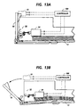
- This bin locking and unlocking system may preferably, but need not necessarily, require separate, individual solenoid or cam operated latches for each bin, as shown, for example, in Figs. 13 and 16. Movement of the compiler unit can also be used to provide bin unlocking by camming open bin door lock latches, for example. Another example of an electrical locking and bin unlocking system is described in the above-cited EPO published application No. 0 241 273.
- the bin locking and unlocking system 50 may comprise simple solenoid bin door latches 54 with simple spring loading to pop each selected door 52 open, and conventional cam or door striker relatching when the door 52 is manually closed.
- Sensors 55 may be used to tell if that door 52 is open or closed, such as conventional optical slot sensors which are blocked by the illustrated tab on the door being in the sensor slot when the door is closed.
- this extra sensor and its connection to control 100 is not required, since a system of dual mode sharing of the "bin empty" sensor for this additional function is also disclosed herein.
- Bins with doors which are open signal controller 100 to not feed further sheets therein until they are closed, for jam and safety reasons.
- a function of locked or restricted access bins with normally closed access doors is to prevent users from putting their hands into a bin area where and when the compiler/stapler unit is operating there or in an adjacent area, or at all, if desired. I.e., an immediately subsequent print job for the user unloading their bin can be routed to another, newly assigned bin, or the printer can be directed by controller 100 to stop printing any jobs for that user, or the printer can be directed to stop any printing until all bin doors are closed.
- separate safety switches can also be used.
- the customer can additionally or alternatively look at the mailbox user interface (UI) liquid crystal (LCD) 104 or other display.
- UI mailbox user interface
- the UI 104 when actuated, may, if desired, scroll through all the various customer names and bin locations of customers currently having jobs in the mailbox unit. Or if anonymous security is desired or selected, the user can be required to enter their access number in order for the job bin(s) location to be displayed. As noted, if locked bin security was designated when sending the job to the printer, the customer can enter a pin (code) number, and the UI can then indicate the location of their job and also unlock those bin(s).
- Another optional user signaling feature is for the mailbox unit to have a conventional beeper or other audio signaling device to tell the operator or user to unload bins when (as soon as) his or her print job is completed (fully stacked in the assigned mailbox bin or bins). This may be in addition to the visual display indicating which bins should be unloaded. This is particularly useful if the user is standing by the mailbox unit while that user's print job is running as in a "print on demand" mode, since the locked bin doors will preferably remain locked until the last sheet is in the last assigned bin.
- the system can also automatically generate a network message back to the job senders terminal, if desired, as soon as a print job is completed and in a bin, so that the users screen displays a status message like "your job is in bin #3"; or "the printer is out of paper”; or the like. Or, as noted below, voice-mail may be used for this.
- the controller 100 can auto-dial such voice mail trigger signals for sending a pre-stored mailbox job receipt voice mail message of the mailbox unit location and/or bin location.
- the system may, if desired, further optionally include the lighting of indicator lamps on or adjacent the user's bin, to direct the user to the proper bin to be unloaded.
- indicator lamps on or adjacent the user's bin, to direct the user to the proper bin to be unloaded.
- those jobs may be electronically stored in the printer or print server buffer memory but not yet printed. That customer would enter their his or her security number, and their jobs would then automatically be placed next in the printer print queue (number one in priority), so as to start printing and sending those jobs to a mailbox.
- the mailbox UI could then also display the estimated time of arrival (ETA) of their job in the bin, as well as the bin number(s) where the job will be placed.
- ETA estimated time of arrival
- a bin empty sensor indicates to the system controller that those emptied bins are available for new job use and/or user re-assignments. Specifically, an in-bin sensor system determines "mailbox" availability.
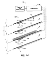
- a unique bin empty sensor system 110 is shown here, in Figs.14 - 16 in particular.
- a single small infra-red or other optical sensor unit 112 is mounted in each tray bottom 13 in a single aperture 13a
- Each single unit 112 has its light beam transmitter 112a on one side and its light sensor (receiver) 112b on the other side. This is so that the light beam from one unit 112 in one bin floor 13 shines up [or down] to the light receiver 112b in the next unit 112 in the bottom of the next bin, and so on. If that bin 11 has any sheets in it, the sheets block the light beam, and the non-receipt of the light by receiving unit 112 so signals.
- the "bin empty" sensor system 110 can reduce hardware and wiring.
- a single sensor unit 112 in the bin floor 13 transmits one light beam 14 from a light transmitter 112a to the light receiving sensor 112b in the next adjacent bin in one direction, while that same sensor unit 112 also normally receives another light beam from the opposite direction from the sensor unit 112 in the oppositely adjacent bin, unless that other light beam was interrupted by sheets in the oppositely adjacent bin.
- each emitter/detector unit 112 works in cooperation with the adjacent said units 112 in the bins above and below, not with itself, as in typical optical sensor units.
- an optical emitter and detector which can be used are an Optek No. OP298 and an Optek No. OP555, mounted as shown in Fig. 14 in a plastic block with smoothly sloped ends or sides in the paper feeding direction so as not to catch sheet ends.
- the top of each unit 112 is preferable level with or below the sheet stacking surface of the bin tray bottom 13, so as to not interfere with sheet movement into or out of the bins.
- these sensor units 112 may each be offset from one another along the bin trays by a distance S which is equal to D sin(a), where "D” is the vertical distance between bin trays and "a” is their angle from the horizontal. Or, they may be mounted sideways, as in Fig. 16.
- this bin empty sensor system 110 can additionally provide dual-mode functionality, by also sensing a drawer or bin opening, as well as unremoved sheet jobs, in individual bins, using the same sensor unit 112. That is, the same light beam blocked by sheets in the bin can also be blocked by the opening of the door to that same bin. [This is discussed further herein in connection with the disclosed bin privacy door systems.]
- a visual interactive indicator for guiding user bin unloading may desirably be provided by automatically opening the privacy doors 52 of the users bins needing unloading when the user enters his or her access or unlocking code. Automatically unlocking and at least partially opening the locked bin doors is preferred, since the opened doors clearly help show or guide the user to the correct bin or bins. Also, the operator can remove the job sheets from inside the bin with one hand, rather them having to use another hand to hold the bin privacy door open.
- This automatic bin door opening can be accomplished as shown in Fig. 13, for example, by a spring-loaded bin door which pops open by spring force when a simple solenoid escapement latch or the like is released by the solenoid receiving an electrical unlocking signal from the mailbox controller.
- the bins themselves may open by sliding out like individual drawers. As shown in Fig. 16, after a user drawer has been released by a solenoid latch, it may pop open a short distance by spring force, and then be operator opened manually the rest of the way for job removal. Then, when it is pushed closed, it relatches like a conventional door.
- the mailbox unit described herein is desirably preset in its controller software to use the above-described dynamic bin assignment for all bins as the automatic default.
- customers can optionally partially override that by a simple software key entry option which pre-assigns one or more bins to a specific user, so that other users cannot use that bin [no other users' print jobs are sent to that bin] until that special override is deleted, or a re-assignment of that bin to another user is entered in the controller.
- a user may similarly chose to have all of their print jobs sent to an open bin or common stacker rather than a separate locked or unlocked mailbox until further notice, e.g., if they will be away for a while, or elect to send all their all print jobs to someone elses mailboxes, such as a secretary.]
- all remaining mailbox bins not so specially preassigned preferably remain free to be dynamically variably assigned.
- the disclosed dynamic mailbox assignment system enables many more users to be able to share a printer than there are mailboxes, yet still have their jobs put into separate mailboxes, by automatically reassigning mailboxes, whenever they are free, to current printer users.
- the number of available mailboxes, and/or the ratio of locked to unlocked mailboxes and/or stacking trays may be readily field retrofitably expanded or changed, if desired.
- the stapler may also be a field retrofittable optional accessory.
- Another user programmable option can be to select whether or not to have the printer generate the usual "banner" (cover) sheets for each print job for that user.
- These job banner sheets may remain desirable, for example, for common stacking of unstapled intermixed jobs, but not necessarily for jobs already segregated by users into separate mailboxes, especially if the jobs are being stapled, as provided in the above-described mailbox unit. Eliminating banner sheets saves paper and improves productivity.
- This banner sheet versus no banner sheet selection is also desirably an automatic system default selection which may be overridden.
- a manual or automatic system default selection of an open common or general use tray in the initial paper path may be made when the user job selection information or printer controller signals that the job is being printed on paper wanting special handling, or more likely to jam in the mailbox bin selection paper path or compiler system, such as carbonless paper, transparencies or envelopes.
- the control algorithm preferably always selects and fills first those available mailbox bins that are closest to the top of the mailbox bin array, since these higher bins are normally the easiest to unload. This is another advantage of this dynamic bin assignment system; all users can normally have an even chance to have an "upper" bin most of the time, except when there is heavy usage and many unremoved print jobs. However, a wheel chair bound or other disadvantaged user may want to have the algorithm programmed for him or her to always be assigned the lowermost available bin(s).
- Figs. 10-13 Another optional feature, for job removal assistance, is disclosed here in Figs. 10-13.
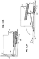
- Unlocking and opening any bin privacy door 52 here also automatically, with a simple, low cost mechanism 120, lifts the exposed front edge of the output sets therein for easy operator removal.
- an integral conventional limited angle or stop hinge (Figs. 10 and 13) or connecting link (Figs. 12) also then begins to pivot up, with further door opening, an arm plate or flap 122 (which lifts up by a lesser total angle), from the tray bottom under that edge of the job set or sets in that bin. That allows the user to easily slide his or her hand under the job set to grasp and remove it from the bin as the bin door is fully opened.
- this set lifter mechanism 120 also may serve to protectively cover, with lifter plate 122, when it is down, the usual bin or tray bottom 13 "cut outs" 13b for set removal assistance, which openings are not appropriate to have open in such a security or lockbox mailbox bin.
- the set lifter 120 flap 122 enables the same bin trays (with cut-outs 13b) to be used for either secured (privacy door) and unsecured (open) bins, which is desirable for a "universal" or modular output device, especially to provide mixed functions and/or interchangeable output mailboxes.
- an audio beeper (and a visual instructional display on the LCD display 104 or the like) is also desirably provided to remind the user to reclose (and thus re-lock) the opened bin door(s), so that they can be reassigned to other users and reused. If the bins are not cleared and/or the bins doors are not so closed after a suitable time delay, another such audio/visual indication can desirably be provided for that.
- controller 100 displays (and may also indicate to the system, e.g., the printer U.I.) from the mailbox memory, jobs printed more than 24 hours earlier and not yet removed from their bins.
- the systems administrator and/or key operator may be prompted by messages to remove those old jobs from mailboxes. He or she may be provided codes giving access to any or all bins for that, or other, purposes.
- Exemplary embodiments above include details of providing both locked and unlocked (regular) mailbox bins, and providing for automatic electronic unlocking of selected mailbox bins with locked access or "privacy” bin doors for particular users by "keying in” users' access codes.
- Other embodiments above indicate that "Workstations on the network with conversion software can interact with the print service,” and “The user can see the status of a print job and its place in the queue by making a request through the print server terminal or at the workstation”. "The system can also automatically generate a network message back to the job senders terminal, if desired, as soon as a print job is completed and in a bin, so that the users screen displays a status message like 'your job is in bin #3'; or 'the printer is out of paper'; or the like.
- voice-mail may be used for this.
- various of the control and software functions described herein may be done in the system printer server rather than in the mailbox unit or the printer unit per se.”
- the subject exemplary embodiment disclosed features of an electronic printer and multibin mailbox system for an electronically networked system of plural users of an electronic printer, in which printer mailbox system the individual users print jobs of printer sheets printed by said printer are automatically variably directed into particular electronically assigned print job storage mailbox bins of said multibin mailbox system, at least some of which mailbox bins are nominally locked but electronically unlockable mailbox bins providing restricted public access privacy storage of confidential print jobs, further including an electronic access code inputting system for individual said users to respectively input a respective access code for unlocking their said electronically assigned electronically unlockable user mailbox bins, and a control system for reporting to said individual said user which said locked mailbox bins are occupied by print jobs, said control system also monitoring and electronically providing a job removal prompting indicator display signal when said uses leave their print jobs unremoved from said mailbox bins for too long a time, exceeding a preset time period; and/or the electronic printer and multibin mailbox system wherein said control system automatically provides a prompting message instructing an operator to remove all print jobs printer more than 24 hours earlier and not yet removed from said
- System 210 includes an Ethernet local area network (LAN) 212, to which a number of user workstations 214, including workstations 214A and 214B, are connected.
- Workstations 214 may be, for example, the Xerox 6085 professional workstation.
- LAN 212 may also have other office-connected equipment, such as network file server 216, network file/mail/communication server 218, printer server 220 and printer 222.
- a large capacity remote storage facility such as a UNIX mini computer 224
- LAN 212 is a collaborative type system, meaning that it enables users at different workstations 214 to work together in real-time by processing and passing information along one another and storing and retrieving information from storage services 214 and 224 via network 212.
- the collaborative functions of system 210 could also be centralised in a single main CPU, could be distributed among processors at the workstations, or could be provided in any combination of centralisation and distribution.
- LAN 212 could take any appropriate configuration capable of providing the necessary communication to support collaboration.
- System 210 includes display-based user interfaces, with each workstation 214 including a display device and a user input device.
- workstations 214A and 214B illustratively include respective CRT display screens 226 and 228 and keyboards 225, each with a display cursor mouse 230.
- System 210 includes an object oriented display system that comprises iconic representations of different structured data objects positioned on a workspace of a display screen, e.g., a display illustrating an office desktop metaphor employing various abstractions of a typical office environment, representative of real office objects. Examples of these in Fig. 1 are a desktop 232, inbasket 233, outbasket 234, documents 235 and 235A, file folder 236, file drawer 237 and printer 238.
- Document icon 235A is shown "opened", in that an ⁇ OPEN> command has been invoked and opened window 235B has appeared displaying the document in full scale.
- Printer 238 is an iconic representation of the shared printer 222 on LAN 212.
- a document 235 is able to be moved, via a ⁇ COPY> command from keyboard 225, onto printer icon 238 and will be printed at printer 222.
- Electronic mail is received and sent via a workstation inbasket 233 and outbasket 234, respectively, from and to other workstations on LAN 212 or to workstations on other networks via File/Mail/Com server 218.
- the desktop 232 of workstations 214A and 214B also includes a shared structured data object 240, which is shown in larger details between workstations 214 and 214B.
- This shared structured data object corresponds to a container of related structured data objects, and the data content of the related structured data objects enables users at different workstations to work together in real time.
- the contained bodies of related structured data objects need not be mutually exclusive.
Landscapes
- Physics & Mathematics (AREA)
- General Physics & Mathematics (AREA)
- Engineering & Computer Science (AREA)
- Microelectronics & Electronic Packaging (AREA)
- Computer Security & Cryptography (AREA)
- Collation Of Sheets And Webs (AREA)
- Supports Or Holders For Household Use (AREA)
Claims (16)
- Système de mise en boîte à lettres pour délivrer des feuilles d'un dispositif de sortie dans un casier de courrier (11) sélectionné parmi une pluralité de casiers de courrier (11) disposés dans un logement avec au moins certains casiers supportés de manière coulissante dans celui-ci, le système comprenant un moyen de commande (100) pour commander le moyen d'alimentation en feuilles, pour délivrer les feuilles du dispositif de sortie dans le casier de courrier sélectionné, le moyen d'alimentation en feuilles comprenant une pluralité de portes de déviation (32), chaque porte de déviation (32) étant associée à un casier de courrier respectif (11), chaque porte de déviation (32) étant individuellement déplaçable à partir d'une première position, permettant aux feuilles de passer par celle-ci pour aller devant son casier associé, à une seconde position pour diriger les feuilles dans son casier associé, et comprenant un moyen d'actionnement (35) pour déplacer sélectivement une des portes de déviation (32) à la seconde position, un moyen de verrouillage (50, 54) pouvant être mis en oeuvre par ledit moyen de commande (100) pour limiter l'accès aux feuilles empilées dans le casier de courrier sélectionné et un moyen de déverrouillage pouvant déverrouiller le moyen de verrouillage afin de procurer l'accès aux feuilles empilées dans le casier sélectionné, le moyen de verrouillage servant à verrouiller le casier de courrier dans le logement afin d'empêcher le déplacement coulissant d'un casier de courrier tandis que les feuilles sont toujours envoyées dans ce casier de courrier et le moyen de déverrouillage servant à déverrouiller les casiers de courrier pour permettre le déplacement coulissant et pour permettre au moins l'enlèvement partiel du casier de courrier du logement seulement lorsque les feuilles ne sont plus envoyées dans le casier de courrier.
- Système de mise en boîte à lettres selon la revendication 1, dans lequel le moyen de déverrouillage peut être mis en oeuvre pour déverrouiller le moyen de verrouillage (50, 54) pour le casier de courrier sélectionné (11) tandis que un ou plusieurs ou la totalité du reste des casiers de courrier reste verrouillé.
- Système de mise en boîte à lettres selon la revendication 1 ou la revendication 2, dans lequel au moins certains des casiers de courrier sont sollicités par ressort de façon à s'ouvrir automatiquement en coulissant comme des tiroirs à partir du logement lorsque libérés par un mécanisme de loquet.
- Système de mise en boîte à lettres selon la revendication 3, dans lequel le mécanisme de loquet est libéré fonctionnellement par un moyen électromagnétique.
- Système de mise en boîte à lettres selon l'une quelconque des revendications 1 à 4, dans lequel le moyen d'alimentation en feuilles comprend un moyen de traitement de feuilles dans le trajet de feuilles d'entrée en amont des casiers pour permettre un choix d'empilage dans le casier des feuilles du type côté ou du type extrémité et/ou la sélection du côté d'un ensemble de feuilles qui doit être agrafé.
- Système de mise en boîte à lettres selon l'une quelconque des revendications 1 à 5,- dans lequel le moyen d'alimentation en feuilles comprend un moyen d'inversion de feuilles pour inverser les feuilles avant d'entrer dans la boîte à lettres.
- Système de mise en boîte à lettres selon l'une quelconque des revendications 1 à 6, dans lequel les casiers de courrier sont électroniquement déverrouillables par des codes d'accès utilisateurs.
- Système de mise en boîte à lettres selon l'une quelconque des revendications 1 à 7, dans lequel le moyen de commande (100) commande variablement la sélection des casiers afin de continuer à diriger les feuilles pour un travail ou des travaux ayant un même code utilisateur dans le même premier casier si le travail ou les travaux ne remplissent pas ce casier et dans un casier de débordement si le travail ou les travaux débordent du premier casier.
- Système de mise en boîte à lettres selon l'une quelconque des revendications 1 à 8, dans lequel un moyen de notification est prévu pour avertir un utilisateur qu'il doit décharger les feuilles d'un travail ou de travaux à partir d'un casier.
- Système de mise en boîte à lettres selon l'une quelconque des revendications 1 à 9, dans lequel une interface utilisateur est prévue, d'où il résulte qu'un utilisateur peut accéder aux feuilles dans le casier sélectionné en entrant son code utilisateur dans l'interface utilisateur.
- Système de mise en boîte à lettres selon la revendication 10, dans lequel l'interface utilisateur comprend un pavé de touches sur lequel l'utilisateur entre son code utilisateur.
- Système de mise en boîte à lettres selon l'une quelconque des revendications 1 à 11, dans lequel le moyen de notification est conçu pour délivrer une instruction d'enlèvement lorsqu'un travail a été laissé dans un casier de courrier au-delà d'une période préétablie.
- Système de mise en boîte à lettres selon l'une quelconque des revendications 1 à 12, dans lequel un moyen d'indicateur de casiers utilisateurs est prévu, le moyen d'indicateur étant mis à jour de manière répétée par le moyen de commande pour identifier les utilisateurs dont les casiers de courrier contiennent des ensembles de travaux pour un utilisateur particulier.
- Système de mise en boîte à lettres selon la revendication 13, dans lequel le moyen d'indicateur de casiers utilisateurs comprend un moyen d'affichage activé par l'entrée d'un code d'accès dans un dispositif d'entrée de code utilisateur pour le moyen de commande.
- Système de mise en boîte à lettres selon l'une quelconque des revendications 1 à 14, dans lequel le dispositif de sortie est une imprimante.
- Système de mise en boîte à lettres selon l'une quelconque des revendications 1 à 15, dans lequel ledit moyen de commande (100) sélectionne lesquels desdits casiers seront affectés à un utilisateur particulier en réponse aux déterminations répétées desquelles des boîtes à lettres sont actuellement disponibles pour empiler des ensembles de travaux dans ceux-ci, un casier étant actuellement disponible pour un autre utilisateur seulement s'il est libre ou a été vidé dans l'intervalle par un utilisateur précédent, mais est actuellement disponible pour le même utilisateur précédemment affecté à ce casier même s'il n'est pas vidé tant que ce casier ne déborde pas dû au travail suivant qui doit être imprimé.
Applications Claiming Priority (4)
| Application Number | Priority Date | Filing Date | Title |
|---|---|---|---|
| US08/054,502 US5358238A (en) | 1993-04-27 | 1993-04-27 | Shared user printer output dynamic "mailbox" system |
| US54502 | 1993-04-27 | ||
| US08/197,092 US5435544A (en) | 1993-04-27 | 1994-02-16 | Printer mailbox system signaling overdue removals of print jobs from mailbox bins |
| US197092 | 1994-02-16 |
Publications (3)
| Publication Number | Publication Date |
|---|---|
| EP0622694A2 EP0622694A2 (fr) | 1994-11-02 |
| EP0622694A3 EP0622694A3 (fr) | 1995-01-04 |
| EP0622694B1 true EP0622694B1 (fr) | 1997-10-15 |
Family
ID=26733103
Family Applications (2)
| Application Number | Title | Priority Date | Filing Date |
|---|---|---|---|
| EP19940303031 Expired - Lifetime EP0622695B1 (fr) | 1993-04-27 | 1994-04-27 | Système de mise en boîte postale pour alimenter des feuilles depuis un dispositif de sortie jusque dans des casiers à courrier sélectionnés |
| EP19940303030 Expired - Lifetime EP0622694B1 (fr) | 1993-04-27 | 1994-04-27 | Système de mise en boîte postale et de tri pour alimenter des feuilles depuis un dispositif de sortie vers des casiers à courrier verrouillables |
Family Applications Before (1)
| Application Number | Title | Priority Date | Filing Date |
|---|---|---|---|
| EP19940303031 Expired - Lifetime EP0622695B1 (fr) | 1993-04-27 | 1994-04-27 | Système de mise en boîte postale pour alimenter des feuilles depuis un dispositif de sortie jusque dans des casiers à courrier sélectionnés |
Country Status (3)
| Country | Link |
|---|---|
| EP (2) | EP0622695B1 (fr) |
| DE (1) | DE69401377T2 (fr) |
| ES (2) | ES2098101T3 (fr) |
Cited By (1)
| Publication number | Priority date | Publication date | Assignee | Title |
|---|---|---|---|---|
| US7719708B2 (en) | 2005-06-01 | 2010-05-18 | Sharp Laboratories Of America, Inc. | Secured release method and system for transmitting and imaging a print job in which a security attribute in the print job header will prevent acceptance of subsequent data packets until a user performs authentication on the imaging device |
Families Citing this family (5)
| Publication number | Priority date | Publication date | Assignee | Title |
|---|---|---|---|---|
| US5346203A (en) * | 1993-08-30 | 1994-09-13 | Xerox Corporation | High capacity sheet stacking system with variable height input and stacking registration |
| US5644685A (en) * | 1994-12-06 | 1997-07-01 | Sun Microsystems, Inc. | Laser printer output director |
| JP2004338295A (ja) | 2003-05-16 | 2004-12-02 | Ricoh Co Ltd | 画像形成装置、画像形成システム、画像形成方法、および画像形成プログラム |
| CN112006505A (zh) * | 2020-09-07 | 2020-12-01 | 安徽引航人广告标识有限公司 | 一种信报箱的信件分类存储装置及其使用方法 |
| CN113183632A (zh) * | 2021-04-23 | 2021-07-30 | 李骏康 | 自动储存云打印机 |
Family Cites Families (18)
| Publication number | Priority date | Publication date | Assignee | Title |
|---|---|---|---|---|
| US4522486A (en) * | 1977-11-10 | 1985-06-11 | International Business Machines Corporation | Method and apparatus for adaptive collation |
| JPS57136865A (en) * | 1981-02-18 | 1982-08-24 | Fujitsu Ltd | Facsimile terminal |
| JPS57175657A (en) * | 1981-04-22 | 1982-10-28 | Canon Inc | Document sorting unit |
| JPS60123155A (ja) * | 1983-12-07 | 1985-07-01 | Canon Inc | 通信端末装置 |
| JPS6186365A (ja) * | 1984-10-03 | 1986-05-01 | Ricoh Co Ltd | ソ−タ |
| JPS62259963A (ja) * | 1986-04-11 | 1987-11-12 | ゼロツクス コ−ポレ−シヨン | 接近を制限された複写機の文書容器 |
| JPS63138883A (ja) * | 1986-11-29 | 1988-06-10 | Toshiba Corp | フアクシミリ装置 |
| JPS6468063A (en) * | 1987-09-09 | 1989-03-14 | Nippon Telegraph & Telephone | Facsimile communication equipment |
| JPH01136470A (ja) * | 1987-11-21 | 1989-05-29 | Tooku:Kk | ファクシミリ受信文書保管装置 |
| JPH01139468A (ja) * | 1987-11-27 | 1989-05-31 | Ricoh Co Ltd | 記録装置の出力装置 |
| JPH01246961A (ja) * | 1988-03-29 | 1989-10-02 | Canon Inc | ファクシミリ装置 |
| US4935771A (en) * | 1988-04-30 | 1990-06-19 | Minolta Camera Kabushiki Kaisha | Copying apparatus having automatic document feeder and sorter |
| JP3148208B2 (ja) * | 1988-10-31 | 2001-03-19 | 富士ゼロックス株式会社 | マルチ出力トレイ付プリントサーバおよびプリントシステム |
| JPH02144372A (ja) * | 1988-11-25 | 1990-06-04 | Canon Inc | ソータ装置 |
| JPH02186429A (ja) * | 1989-01-13 | 1990-07-20 | Hitachi Ltd | ネツトワーク型印刷システム |
| SG52343A1 (en) * | 1991-12-24 | 1998-09-28 | Seiko Epson Corp | Printing apparatus |
| US5328170A (en) * | 1992-03-10 | 1994-07-12 | Gradco (Japan) Ltd. | Locked drawer sorter |
| EP0585075B1 (fr) * | 1992-08-24 | 1997-11-05 | Xerox Corporation | Système de distribution de feuilles imprimées séquentiellement sorties dans des cases de tri individuellement et variablement assignables |
-
1994
- 1994-04-27 ES ES94303031T patent/ES2098101T3/es not_active Expired - Lifetime
- 1994-04-27 ES ES94303030T patent/ES2110697T3/es not_active Expired - Lifetime
- 1994-04-27 DE DE1994601377 patent/DE69401377T2/de not_active Expired - Fee Related
- 1994-04-27 EP EP19940303031 patent/EP0622695B1/fr not_active Expired - Lifetime
- 1994-04-27 EP EP19940303030 patent/EP0622694B1/fr not_active Expired - Lifetime
Cited By (1)
| Publication number | Priority date | Publication date | Assignee | Title |
|---|---|---|---|---|
| US7719708B2 (en) | 2005-06-01 | 2010-05-18 | Sharp Laboratories Of America, Inc. | Secured release method and system for transmitting and imaging a print job in which a security attribute in the print job header will prevent acceptance of subsequent data packets until a user performs authentication on the imaging device |
Also Published As
| Publication number | Publication date |
|---|---|
| EP0622694A2 (fr) | 1994-11-02 |
| ES2098101T3 (es) | 1997-04-16 |
| DE69401377D1 (de) | 1997-02-20 |
| DE69401377T2 (de) | 1997-07-10 |
| EP0622695A1 (fr) | 1994-11-02 |
| EP0622694A3 (fr) | 1995-01-04 |
| ES2110697T3 (es) | 1998-02-16 |
| EP0622695B1 (fr) | 1997-01-08 |
Similar Documents
| Publication | Publication Date | Title |
|---|---|---|
| US5435544A (en) | Printer mailbox system signaling overdue removals of print jobs from mailbox bins | |
| US5342034A (en) | Mailbox/compiler architecture | |
| US5328169A (en) | Mailbox or sorter bin use sensing system | |
| US5390910A (en) | Modular multifunctional mailbox unit with interchangeable sub-modules | |
| US5308058A (en) | Mailbox security door with automatic set lifter | |
| US5525031A (en) | Automated print jobs distribution system for shared user centralized printer | |
| US5547178A (en) | Printer mailbox split jobs overflow banner sheet indicator system | |
| EP0729077B1 (fr) | Système à impression et à boíte aux lettres avec détection de récepteurs de copies presque pleins | |
| JP3822291B2 (ja) | メールボックスシステム | |
| EP0768265B1 (fr) | Capteur de hauteur pour piles individuelles dans un système contenant plusieurs récepteurs d'empilage de feuilles | |
| EP0768263B1 (fr) | Système de contrôle de hauteur d'une pile de feuilles | |
| US5898592A (en) | Sheet delivery control system | |
| US5603492A (en) | Sheet stacking bin fullness control system | |
| EP0657377B1 (fr) | Système de mise un boíte postale et système d'impilage de jeux de feuilles intégré | |
| US5704609A (en) | Integrated inter-mailbox modules bypass transport and purge tray system | |
| US5697761A (en) | Mailbox bin job set extractor | |
| EP0622694B1 (fr) | Système de mise en boîte postale et de tri pour alimenter des feuilles depuis un dispositif de sortie vers des casiers à courrier verrouillables | |
| JP3822290B2 (ja) | メールボックスシステム | |
| JP2801855B2 (ja) | メールボックスビンからの印刷ジョブの取り忘れを合図する印刷装置メールボックスシステム | |
| JP2000128424A (ja) | プリンティングシステムのジョブルーティングシステム | |
| JPS63180675A (ja) | 画像形成装置 |
Legal Events
| Date | Code | Title | Description |
|---|---|---|---|
| PUAI | Public reference made under article 153(3) epc to a published international application that has entered the european phase |
Free format text: ORIGINAL CODE: 0009012 |
|
| AK | Designated contracting states |
Kind code of ref document: A2 Designated state(s): BE ES FR IT NL |
|
| PUAL | Search report despatched |
Free format text: ORIGINAL CODE: 0009013 |
|
| AK | Designated contracting states |
Kind code of ref document: A3 Designated state(s): BE ES FR IT NL |
|
| 17P | Request for examination filed |
Effective date: 19950704 |
|
| 17Q | First examination report despatched |
Effective date: 19950828 |
|
| GRAG | Despatch of communication of intention to grant |
Free format text: ORIGINAL CODE: EPIDOS AGRA |
|
| GRAH | Despatch of communication of intention to grant a patent |
Free format text: ORIGINAL CODE: EPIDOS IGRA |
|
| GRAH | Despatch of communication of intention to grant a patent |
Free format text: ORIGINAL CODE: EPIDOS IGRA |
|
| GRAA | (expected) grant |
Free format text: ORIGINAL CODE: 0009210 |
|
| AK | Designated contracting states |
Kind code of ref document: B1 Designated state(s): BE ES FR IT NL |
|
| ITF | It: translation for a ep patent filed | ||
| REG | Reference to a national code |
Ref country code: ES Ref legal event code: FG2A Ref document number: 2110697 Country of ref document: ES Kind code of ref document: T3 |
|
| ET | Fr: translation filed | ||
| PLBE | No opposition filed within time limit |
Free format text: ORIGINAL CODE: 0009261 |
|
| STAA | Information on the status of an ep patent application or granted ep patent |
Free format text: STATUS: NO OPPOSITION FILED WITHIN TIME LIMIT |
|
| 26N | No opposition filed | ||
| PGFP | Annual fee paid to national office [announced via postgrant information from national office to epo] |
Ref country code: FR Payment date: 20020410 Year of fee payment: 9 |
|
| PGFP | Annual fee paid to national office [announced via postgrant information from national office to epo] |
Ref country code: ES Payment date: 20020417 Year of fee payment: 9 |
|
| PGFP | Annual fee paid to national office [announced via postgrant information from national office to epo] |
Ref country code: NL Payment date: 20020426 Year of fee payment: 9 |
|
| PGFP | Annual fee paid to national office [announced via postgrant information from national office to epo] |
Ref country code: BE Payment date: 20020627 Year of fee payment: 9 |
|
| PG25 | Lapsed in a contracting state [announced via postgrant information from national office to epo] |
Ref country code: ES Free format text: LAPSE BECAUSE OF NON-PAYMENT OF DUE FEES Effective date: 20030428 |
|
| PG25 | Lapsed in a contracting state [announced via postgrant information from national office to epo] |
Ref country code: BE Free format text: LAPSE BECAUSE OF NON-PAYMENT OF DUE FEES Effective date: 20030430 |
|
| BERE | Be: lapsed |
Owner name: *XEROX CORP. Effective date: 20030430 |
|
| PG25 | Lapsed in a contracting state [announced via postgrant information from national office to epo] |
Ref country code: NL Free format text: LAPSE BECAUSE OF NON-PAYMENT OF DUE FEES Effective date: 20031101 |
|
| NLV4 | Nl: lapsed or anulled due to non-payment of the annual fee |
Effective date: 20031101 |
|
| PG25 | Lapsed in a contracting state [announced via postgrant information from national office to epo] |
Ref country code: FR Free format text: LAPSE BECAUSE OF NON-PAYMENT OF DUE FEES Effective date: 20031231 |
|
| REG | Reference to a national code |
Ref country code: FR Ref legal event code: ST |
|
| REG | Reference to a national code |
Ref country code: ES Ref legal event code: FD2A Effective date: 20030428 |
|
| PG25 | Lapsed in a contracting state [announced via postgrant information from national office to epo] |
Ref country code: IT Free format text: LAPSE BECAUSE OF NON-PAYMENT OF DUE FEES;WARNING: LAPSES OF ITALIAN PATENTS WITH EFFECTIVE DATE BEFORE 2007 MAY HAVE OCCURRED AT ANY TIME BEFORE 2007. THE CORRECT EFFECTIVE DATE MAY BE DIFFERENT FROM THE ONE RECORDED. Effective date: 20050427 |