EP0622831A1 - Procédé de fabrication d'une lampe à décharge de mercure à basse pression - Google Patents
Procédé de fabrication d'une lampe à décharge de mercure à basse pression Download PDFInfo
- Publication number
- EP0622831A1 EP0622831A1 EP93305253A EP93305253A EP0622831A1 EP 0622831 A1 EP0622831 A1 EP 0622831A1 EP 93305253 A EP93305253 A EP 93305253A EP 93305253 A EP93305253 A EP 93305253A EP 0622831 A1 EP0622831 A1 EP 0622831A1
- Authority
- EP
- European Patent Office
- Prior art keywords
- discharge tubes
- discharge
- tubes
- blisters
- thereafter
- Prior art date
- Legal status (The legal status is an assumption and is not a legal conclusion. Google has not performed a legal analysis and makes no representation as to the accuracy of the status listed.)
- Granted
Links
Images

Classifications
-
- H—ELECTRICITY
- H01—ELECTRIC ELEMENTS
- H01J—ELECTRIC DISCHARGE TUBES OR DISCHARGE LAMPS
- H01J61/00—Gas-discharge or vapour-discharge lamps
- H01J61/02—Details
- H01J61/30—Vessels; Containers
- H01J61/32—Special longitudinal shape, e.g. for advertising purposes
- H01J61/325—U-shaped lamps
-
- H—ELECTRICITY
- H01—ELECTRIC ELEMENTS
- H01J—ELECTRIC DISCHARGE TUBES OR DISCHARGE LAMPS
- H01J9/00—Apparatus or processes specially adapted for the manufacture, installation, removal, maintenance of electric discharge tubes, discharge lamps, or parts thereof; Recovery of material from discharge tubes or lamps
- H01J9/24—Manufacture or joining of vessels, leading-in conductors or bases
- H01J9/26—Sealing together parts of vessels
- H01J9/265—Sealing together parts of vessels specially adapted for gas-discharge tubes or lamps
- H01J9/266—Sealing together parts of vessels specially adapted for gas-discharge tubes or lamps specially adapted for gas-discharge lamps
Definitions
- This invention relates to a method of producing a low-pressure mercury vapour discharge lamp.
- the invention may also be applicable to the production of other types of discharge lamps.
- the invention relates to a method of producing a low-pressure mercury vapour discharge lamp comprising two or more substantially parallel co-extending glass discharge tubes, the discharge spaces of two adjacent discharge tubes being inter-connected by a coupling tube extending transverse to the axes of the discharge tubes, such that during operation of the lamp, the discharge passes predominantly through the discharge tube, and in which method the discharge tubes are first coated on the inside with a luminescent layer and then closed at one end.
- a method is disclosed in German patent specification 858,105.
- German patent specification 858,105 describes a method in which the above-mentioned lamps are produced by providing an aperture in the glass wall of the discharge tube prior to deposition of a luminescent layer, the connecting coupling tubes being sealed thereto after the application of the luminescent layer.
- UK patent specification GB 2 048 562B recognises that this method has the drawback that during the process of coating the discharge tube wall with luminescent material, which is often done by means of a suspension, liquid material can easily flow out through the aperture so that it is difficult to realise a uniform coating on the wall. There is also the risk that fusion of the coupling tube to the discharge tube is made difficult by enclosure of luminescent material in the glass seal. This may cause stresses in the glass and the chance of fracture is considerable.
- the above mentioned UK patent specification proposes that such lamps are produced by a method in which the inner wall of the discharge tube is first coated with a luminescent layer and then sealed at one end. Once a luminescent layer has been deposited on the inner wall, the tube is heated to form an aperture. The aperture is formed with an outwardly facing collar. This process is repeated with a second discharge tube and the tubes are then placed with their apertures opposite one another. The collars are then fused together by further heating to form a coupling tube.
- Such a method has the drawback that exhaust gas, particles and even oil contained in the fuel supply piping will be unavoidably introduced into the gas discharge tube from the apertures.
- An object of the present invention is to provide a method of inter-connecting two discharge tubes in a low-pressure mercury vapour discharge lamp without polluting the luminescent material inside the discharge tubes and/or providing improvements in relation to one or more of the matters discussed above, or generally.
- a method of producing a low-pressure mercury vapour discharge lamp comprising two or more substantially parallel co-extending glass discharge tubes, the discharge spaces of two adjacent discharge tubes being inter-connected by an inter-connecting joint extending transversely to the wall of those discharge tubes.
- the discharge passes through the greater part of the discharge tubes.
- the inner walls of the discharge tubes are first coated with a luminescent layer and sealed at one end. After the provision of the luminescent layer to the inner walls of the discharge tubes, the connection between the discharge tubes is formed by placing the discharge tubes adjacent to each other and heating at points opposite to one another so that blisters are formed naturally on the wall of the discharge tubes.
- the blisters are formed on the walls of the discharge tubes by heating at the points on the discharge tubes opposite to one another, these points thereafter being enlarged by applying regulated pressurised gas, and thereafter being joined by moving the discharge tubes close together, and thereafter being broken by applying regulated pressurised gas in one or more directions inside the discharge tubes so that a connection between the discharge tubes is formed.
- the glass discharge tubes are joined by a simultaneous fusing and joining process and, as no aperture is formed, no pollutants such as exhaust gas, particles and oil contained in the fuel supply piping will be introduced into the discharge tubes to pollute the luminescent material inside.
- the method of the present invention results in lower internal stresses in the glass, and the risk of fracture and leakage in the region of the connection is greatly reduced.
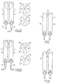
- a discharge lamp to be produced according to the method of the present invention comprises two glass discharge tubes 2 and 4, as shown in Fig 1 and Fig 2. Each tube 2 and 4 is coated with a luminescent layer 6.
- the tubes 2 and 4 are sealed at one end 8.
- the inner surface of the sealed end 8 is also coated with a luminescent layer 6.
- a stem 10 is located at the end of the tube 2 remote from the sealed end 8.
- An electrode 12 and an exhaust tube 14, 15 are connected to the stem 10.
- two discharge tubes of the type shown in Fig 1 are placed adjacent each other so that they are parallel and co-extensive.
- heat 16 is applied simultaneously to opposite points on the side walls of the tubes 2 and 4, so that blisters 18 and 20 are naturally formed.
- gas is introduced through exhaust tubes 14 and 15, applying a regulated pressure which enlarges the blisters 18 and 20.
- the blisters 18 and 20 are then subjected to further heating (Fig 5) and thereafter the discharge tubes 2 and 4 are moved close to each other so as to join them together, as shown in Fig 6.
- Pressurised gas is then introduced into the discharge tubes 2 and 4, either from one exhaust tube 14 (as shown in Fig 6A) or through both exhaust tubes 14 and 15 (as shown in Fig 6B).
- Application of the gas pressure to the blisters 18 and 20 results in their breakage and the simultaneous formation of a joint 22.
- the discharge tubes 2 and 4 are pulled apart (as shown in Fig 7) to the required separation, forming lamp 24, shown in Fig 8.
- This step of pulling the connected tubes apart eliminates uneven glass accumulated at the joint between the discharge tubes, so reducing the internal stresses in the glass. Thus the risk of fracture and leakage in this region is greatly reduced.
Landscapes
- Engineering & Computer Science (AREA)
- Manufacturing & Machinery (AREA)
- Manufacture Of Electron Tubes, Discharge Lamp Vessels, Lead-In Wires, And The Like (AREA)
- Vessels And Coating Films For Discharge Lamps (AREA)
- Pharmaceuticals Containing Other Organic And Inorganic Compounds (AREA)
- Ultra Sonic Daignosis Equipment (AREA)
- Electrophonic Musical Instruments (AREA)
Applications Claiming Priority (2)
| Application Number | Priority Date | Filing Date | Title |
|---|---|---|---|
| GB9308694A GB2277634B (en) | 1993-04-27 | 1993-04-27 | Method of producing a low-pressure mercury vapour discharge lamp |
| GB9308694 | 1993-04-27 |
Publications (2)
| Publication Number | Publication Date |
|---|---|
| EP0622831A1 true EP0622831A1 (fr) | 1994-11-02 |
| EP0622831B1 EP0622831B1 (fr) | 1998-02-18 |
Family
ID=10734556
Family Applications (1)
| Application Number | Title | Priority Date | Filing Date |
|---|---|---|---|
| EP93305253A Expired - Lifetime EP0622831B1 (fr) | 1993-04-27 | 1993-07-05 | Procédé de fabrication d'une lampe à décharge de mercure à basse pression |
Country Status (7)
| Country | Link |
|---|---|
| US (1) | US5423704A (fr) |
| EP (1) | EP0622831B1 (fr) |
| CN (1) | CN1094539A (fr) |
| AT (1) | ATE163331T1 (fr) |
| DE (1) | DE69317041T2 (fr) |
| FI (1) | FI933087A7 (fr) |
| GB (1) | GB2277634B (fr) |
Cited By (4)
| Publication number | Priority date | Publication date | Assignee | Title |
|---|---|---|---|---|
| WO1995017002A3 (fr) * | 1993-12-16 | 1995-08-10 | Dieter Strueber | Procede de fabrication d'une lampe a decharge et lampe a decharge fabriquee selon ce procede |
| WO1996016427A1 (fr) * | 1994-11-17 | 1996-05-30 | Promatec Gmbh Berlin | Procede de raccordement de chambres de decharge de tubes a gaz |
| KR100459777B1 (ko) * | 1996-05-22 | 2005-02-28 | 오스람 실바니아 인코포레이티드 | 관형폐루프램프밀봉체및그제조방법 |
| WO2009100971A1 (fr) * | 2008-02-14 | 2009-08-20 | Osram Gesellschaft mit beschränkter Haftung | Procédé de fabrication d’une enceinte pour une lampe à décharge |
Families Citing this family (2)
| Publication number | Priority date | Publication date | Assignee | Title |
|---|---|---|---|---|
| JP3322390B2 (ja) * | 1998-03-20 | 2002-09-09 | 松下電器産業株式会社 | 蛍光灯の製造方法 |
| CN104609714B (zh) * | 2015-02-13 | 2016-08-31 | 李家凌 | 一种双玻璃管焊接装置 |
Citations (4)
| Publication number | Priority date | Publication date | Assignee | Title |
|---|---|---|---|---|
| JPS59103245A (ja) * | 1982-12-06 | 1984-06-14 | Mitsubishi Electric Corp | 放電ランプの製造方法 |
| US4530710A (en) * | 1983-10-24 | 1985-07-23 | Gte Products Corporation | Low-pressure arc discharge lamp having parallel discharge tubes with an arc-containing interconnecting channel; and method of manufacturing same |
| JPS61224236A (ja) * | 1985-03-27 | 1986-10-04 | Toshiba Corp | 曲管形けい光ランプの製造方法 |
| US4648850A (en) * | 1986-02-24 | 1987-03-10 | Gte Products Corporation | Low-pressure arc discharge lamp having a common passageway and method of manufacturing same |
Family Cites Families (5)
| Publication number | Priority date | Publication date | Assignee | Title |
|---|---|---|---|---|
| NL187138C (nl) * | 1979-04-03 | 1991-06-03 | Philips Nv | Werkwijze voor het vervaardigen van een lagedrukkwikdampontladingslamp. |
| WO1985000926A1 (fr) * | 1983-08-12 | 1985-02-28 | Mitsubishi Denki Kabushiki Kaisha | Lampe a arc a vapeur de mercure a basse pression et son procede de fabrication |
| JPH01173542A (ja) * | 1987-12-25 | 1989-07-10 | Nec Home Electron Ltd | 片口金小形蛍光ランプの整造方法 |
| JPH01173543A (ja) * | 1987-12-25 | 1989-07-10 | Nec Home Electron Ltd | 片口金小形蛍光ランプの製造方法 |
| JPH03171527A (ja) * | 1989-11-29 | 1991-07-25 | Toshiba Lighting & Technol Corp | 蛍光ランプの製造方法 |
-
1993
- 1993-04-27 GB GB9308694A patent/GB2277634B/en not_active Expired - Fee Related
- 1993-07-05 EP EP93305253A patent/EP0622831B1/fr not_active Expired - Lifetime
- 1993-07-05 AT AT93305253T patent/ATE163331T1/de not_active IP Right Cessation
- 1993-07-05 FI FI933087A patent/FI933087A7/fi unknown
- 1993-07-05 DE DE69317041T patent/DE69317041T2/de not_active Expired - Fee Related
- 1993-07-12 US US08/089,331 patent/US5423704A/en not_active Expired - Fee Related
- 1993-11-17 CN CN93114811.1A patent/CN1094539A/zh active Pending
Patent Citations (4)
| Publication number | Priority date | Publication date | Assignee | Title |
|---|---|---|---|---|
| JPS59103245A (ja) * | 1982-12-06 | 1984-06-14 | Mitsubishi Electric Corp | 放電ランプの製造方法 |
| US4530710A (en) * | 1983-10-24 | 1985-07-23 | Gte Products Corporation | Low-pressure arc discharge lamp having parallel discharge tubes with an arc-containing interconnecting channel; and method of manufacturing same |
| JPS61224236A (ja) * | 1985-03-27 | 1986-10-04 | Toshiba Corp | 曲管形けい光ランプの製造方法 |
| US4648850A (en) * | 1986-02-24 | 1987-03-10 | Gte Products Corporation | Low-pressure arc discharge lamp having a common passageway and method of manufacturing same |
Non-Patent Citations (2)
| Title |
|---|
| PATENT ABSTRACTS OF JAPAN vol. 11, no. 65 (E - 484) 27 February 1987 (1987-02-27) * |
| PATENT ABSTRACTS OF JAPAN vol. 8, no. 217 (E - 270) 4 October 1984 (1984-10-04) * |
Cited By (4)
| Publication number | Priority date | Publication date | Assignee | Title |
|---|---|---|---|---|
| WO1995017002A3 (fr) * | 1993-12-16 | 1995-08-10 | Dieter Strueber | Procede de fabrication d'une lampe a decharge et lampe a decharge fabriquee selon ce procede |
| WO1996016427A1 (fr) * | 1994-11-17 | 1996-05-30 | Promatec Gmbh Berlin | Procede de raccordement de chambres de decharge de tubes a gaz |
| KR100459777B1 (ko) * | 1996-05-22 | 2005-02-28 | 오스람 실바니아 인코포레이티드 | 관형폐루프램프밀봉체및그제조방법 |
| WO2009100971A1 (fr) * | 2008-02-14 | 2009-08-20 | Osram Gesellschaft mit beschränkter Haftung | Procédé de fabrication d’une enceinte pour une lampe à décharge |
Also Published As
| Publication number | Publication date |
|---|---|
| GB2277634B (en) | 1996-09-04 |
| GB9308694D0 (en) | 1993-06-09 |
| FI933087L (fi) | 1994-10-28 |
| ATE163331T1 (de) | 1998-03-15 |
| FI933087A0 (fi) | 1993-07-05 |
| DE69317041T2 (de) | 1998-07-23 |
| DE69317041D1 (de) | 1998-03-26 |
| US5423704A (en) | 1995-06-13 |
| EP0622831B1 (fr) | 1998-02-18 |
| FI933087A7 (fi) | 1994-10-28 |
| CN1094539A (zh) | 1994-11-02 |
| GB2277634A (en) | 1994-11-02 |
Similar Documents
| Publication | Publication Date | Title |
|---|---|---|
| US4324447A (en) | Method of producing a low-pressure mercury vapor discharge lamp | |
| EP0622831B1 (fr) | Procédé de fabrication d'une lampe à décharge de mercure à basse pression | |
| US4530710A (en) | Low-pressure arc discharge lamp having parallel discharge tubes with an arc-containing interconnecting channel; and method of manufacturing same | |
| CN1089480C (zh) | 闭环管灯管及其制造方法 | |
| US4648850A (en) | Low-pressure arc discharge lamp having a common passageway and method of manufacturing same | |
| US5090931A (en) | Method of producing a lamp having a coated layer and the lamp produced thereby | |
| US5549496A (en) | Method of producing a low-pressure mercury vapor discharge lamp | |
| US5833506A (en) | Method for manufacturing a fluorescent lamp | |
| EP0672627A1 (fr) | Procédé de fabrication d'une lampe à décharge à mercure à basse pression | |
| KR890001139B1 (ko) | 유리관 성형방법 | |
| KR100966078B1 (ko) | 단부 마감 부재, 방전 램프 및 상기 방전 램프를 제조하는 방법 | |
| EP1187162B1 (fr) | Procédé de fabrication d'une lampe fluorescente | |
| RU2469431C2 (ru) | Способ соединения баллона разрядника газоразрядной лампы с патрубком, в частности со штенгелем | |
| CN1108794A (zh) | 制造低压汞汽放电灯的方法 | |
| JPH01117236A (ja) | 蛍光ランプの製造方法 | |
| JPS62154431A (ja) | 屈曲形けい光ランプの封止方法 | |
| JPS63131435A (ja) | 屈曲形けい光ランプの製造方法 | |
| JPH04138652A (ja) | 屈曲形偏平バルブ | |
| JPS61247631A (ja) | ガラス管の成形方法 | |
| JPS62287545A (ja) | 蛍光ランプの製造方法 | |
| JPS6358734A (ja) | 曲管形けい光ランプの製造方法 | |
| KR19980020391A (ko) | 다수개의 방전유닛을 갖는 컴팩트 형광램프의 방전통로 형성방법 | |
| JPS63134528A (ja) | ガラス管の接合方法 | |
| JPH0668951B2 (ja) | 蛍光ランプの製造方法 | |
| JPS63170827A (ja) | けい光ランプの封止方法 |
Legal Events
| Date | Code | Title | Description |
|---|---|---|---|
| PUAI | Public reference made under article 153(3) epc to a published international application that has entered the european phase |
Free format text: ORIGINAL CODE: 0009012 |
|
| AK | Designated contracting states |
Kind code of ref document: A1 Designated state(s): AT BE CH DE DK ES FR GR IE IT LI LU MC NL PT SE |
|
| 17P | Request for examination filed |
Effective date: 19950310 |
|
| 17Q | First examination report despatched |
Effective date: 19951124 |
|
| GRAG | Despatch of communication of intention to grant |
Free format text: ORIGINAL CODE: EPIDOS AGRA |
|
| GRAG | Despatch of communication of intention to grant |
Free format text: ORIGINAL CODE: EPIDOS AGRA |
|
| GRAH | Despatch of communication of intention to grant a patent |
Free format text: ORIGINAL CODE: EPIDOS IGRA |
|
| GRAH | Despatch of communication of intention to grant a patent |
Free format text: ORIGINAL CODE: EPIDOS IGRA |
|
| GRAA | (expected) grant |
Free format text: ORIGINAL CODE: 0009210 |
|
| AK | Designated contracting states |
Kind code of ref document: B1 Designated state(s): AT BE CH DE DK ES FR GR IE IT LI LU MC NL PT SE |
|
| PG25 | Lapsed in a contracting state [announced via postgrant information from national office to epo] |
Ref country code: LI Free format text: LAPSE BECAUSE OF FAILURE TO SUBMIT A TRANSLATION OF THE DESCRIPTION OR TO PAY THE FEE WITHIN THE PRESCRIBED TIME-LIMIT Effective date: 19980218 Ref country code: GR Free format text: LAPSE BECAUSE OF FAILURE TO SUBMIT A TRANSLATION OF THE DESCRIPTION OR TO PAY THE FEE WITHIN THE PRESCRIBED TIME-LIMIT Effective date: 19980218 Ref country code: ES Free format text: THE PATENT HAS BEEN ANNULLED BY A DECISION OF A NATIONAL AUTHORITY Effective date: 19980218 Ref country code: CH Free format text: LAPSE BECAUSE OF FAILURE TO SUBMIT A TRANSLATION OF THE DESCRIPTION OR TO PAY THE FEE WITHIN THE PRESCRIBED TIME-LIMIT Effective date: 19980218 Ref country code: AT Free format text: LAPSE BECAUSE OF FAILURE TO SUBMIT A TRANSLATION OF THE DESCRIPTION OR TO PAY THE FEE WITHIN THE PRESCRIBED TIME-LIMIT Effective date: 19980218 |
|
| REF | Corresponds to: |
Ref document number: 163331 Country of ref document: AT Date of ref document: 19980315 Kind code of ref document: T |
|
| REG | Reference to a national code |
Ref country code: CH Ref legal event code: EP |
|
| REF | Corresponds to: |
Ref document number: 69317041 Country of ref document: DE Date of ref document: 19980326 |
|
| ET | Fr: translation filed | ||
| ITF | It: translation for a ep patent filed | ||
| PG25 | Lapsed in a contracting state [announced via postgrant information from national office to epo] |
Ref country code: SE Free format text: LAPSE BECAUSE OF FAILURE TO SUBMIT A TRANSLATION OF THE DESCRIPTION OR TO PAY THE FEE WITHIN THE PRESCRIBED TIME-LIMIT Effective date: 19980518 Ref country code: PT Free format text: LAPSE BECAUSE OF FAILURE TO SUBMIT A TRANSLATION OF THE DESCRIPTION OR TO PAY THE FEE WITHIN THE PRESCRIBED TIME-LIMIT Effective date: 19980518 Ref country code: DK Free format text: LAPSE BECAUSE OF FAILURE TO SUBMIT A TRANSLATION OF THE DESCRIPTION OR TO PAY THE FEE WITHIN THE PRESCRIBED TIME-LIMIT Effective date: 19980518 |
|
| REG | Reference to a national code |
Ref country code: IE Ref legal event code: FG4D Free format text: 78935 |
|
| PG25 | Lapsed in a contracting state [announced via postgrant information from national office to epo] |
Ref country code: LU Free format text: LAPSE BECAUSE OF NON-PAYMENT OF DUE FEES Effective date: 19980705 Ref country code: IE Free format text: LAPSE BECAUSE OF NON-PAYMENT OF DUE FEES Effective date: 19980705 |
|
| PGFP | Annual fee paid to national office [announced via postgrant information from national office to epo] |
Ref country code: NL Payment date: 19980728 Year of fee payment: 6 |
|
| REG | Reference to a national code |
Ref country code: CH Ref legal event code: PL |
|
| PGFP | Annual fee paid to national office [announced via postgrant information from national office to epo] |
Ref country code: BE Payment date: 19980914 Year of fee payment: 6 |
|
| PLBE | No opposition filed within time limit |
Free format text: ORIGINAL CODE: 0009261 |
|
| STAA | Information on the status of an ep patent application or granted ep patent |
Free format text: STATUS: NO OPPOSITION FILED WITHIN TIME LIMIT |
|
| PG25 | Lapsed in a contracting state [announced via postgrant information from national office to epo] |
Ref country code: MC Free format text: LAPSE BECAUSE OF NON-PAYMENT OF DUE FEES Effective date: 19990131 |
|
| 26N | No opposition filed | ||
| PGFP | Annual fee paid to national office [announced via postgrant information from national office to epo] |
Ref country code: DE Payment date: 19990706 Year of fee payment: 7 |
|
| PGFP | Annual fee paid to national office [announced via postgrant information from national office to epo] |
Ref country code: FR Payment date: 19990709 Year of fee payment: 7 |
|
| PG25 | Lapsed in a contracting state [announced via postgrant information from national office to epo] |
Ref country code: BE Free format text: LAPSE BECAUSE OF NON-PAYMENT OF DUE FEES Effective date: 19990731 |
|
| BERE | Be: lapsed |
Owner name: MASS TECHNOLOGY (H.K.) LTD Effective date: 19990731 |
|
| PG25 | Lapsed in a contracting state [announced via postgrant information from national office to epo] |
Ref country code: NL Free format text: LAPSE BECAUSE OF NON-PAYMENT OF DUE FEES Effective date: 20000201 |
|
| NLV4 | Nl: lapsed or anulled due to non-payment of the annual fee |
Effective date: 20000201 |
|
| PG25 | Lapsed in a contracting state [announced via postgrant information from national office to epo] |
Ref country code: FR Free format text: LAPSE BECAUSE OF NON-PAYMENT OF DUE FEES Effective date: 20010330 |
|
| REG | Reference to a national code |
Ref country code: FR Ref legal event code: ST |
|
| PG25 | Lapsed in a contracting state [announced via postgrant information from national office to epo] |
Ref country code: DE Free format text: LAPSE BECAUSE OF NON-PAYMENT OF DUE FEES Effective date: 20010501 |
|
| PG25 | Lapsed in a contracting state [announced via postgrant information from national office to epo] |
Ref country code: IT Free format text: LAPSE BECAUSE OF NON-PAYMENT OF DUE FEES;WARNING: LAPSES OF ITALIAN PATENTS WITH EFFECTIVE DATE BEFORE 2007 MAY HAVE OCCURRED AT ANY TIME BEFORE 2007. THE CORRECT EFFECTIVE DATE MAY BE DIFFERENT FROM THE ONE RECORDED. Effective date: 20050705 |