EP0623183B1 - Element de montage profile destine a recevoir et a maintenir differents elements de fixation et/ou de deplacement d'un store a bannes - Google Patents
Element de montage profile destine a recevoir et a maintenir differents elements de fixation et/ou de deplacement d'un store a bannes Download PDFInfo
- Publication number
- EP0623183B1 EP0623183B1 EP93902176A EP93902176A EP0623183B1 EP 0623183 B1 EP0623183 B1 EP 0623183B1 EP 93902176 A EP93902176 A EP 93902176A EP 93902176 A EP93902176 A EP 93902176A EP 0623183 B1 EP0623183 B1 EP 0623183B1
- Authority
- EP
- European Patent Office
- Prior art keywords
- recesses
- mounting element
- awning
- profile mounting
- awning according
- Prior art date
- Legal status (The legal status is an assumption and is not a legal conclusion. Google has not performed a legal analysis and makes no representation as to the accuracy of the status listed.)
- Expired - Lifetime
Links
- 239000004744 fabric Substances 0.000 claims description 18
- 229910052782 aluminium Inorganic materials 0.000 claims description 4
- XAGFODPZIPBFFR-UHFFFAOYSA-N aluminium Chemical compound [Al] XAGFODPZIPBFFR-UHFFFAOYSA-N 0.000 claims description 3
- 238000005260 corrosion Methods 0.000 claims description 2
- 230000007797 corrosion Effects 0.000 claims description 2
- 239000004411 aluminium Substances 0.000 claims 2
- 239000000956 alloy Substances 0.000 claims 1
- 229910045601 alloy Inorganic materials 0.000 claims 1
- 239000011248 coating agent Substances 0.000 claims 1
- 238000000576 coating method Methods 0.000 claims 1
- 229910052751 metal Inorganic materials 0.000 claims 1
- 239000002184 metal Substances 0.000 claims 1
- 238000000034 method Methods 0.000 claims 1
- 238000005096 rolling process Methods 0.000 claims 1
- 238000010276 construction Methods 0.000 description 5
- 238000004519 manufacturing process Methods 0.000 description 3
- 241000950638 Symphysodon discus Species 0.000 description 2
- 238000005516 engineering process Methods 0.000 description 2
- HOQADATXFBOEGG-UHFFFAOYSA-N isofenphos Chemical compound CCOP(=S)(NC(C)C)OC1=CC=CC=C1C(=O)OC(C)C HOQADATXFBOEGG-UHFFFAOYSA-N 0.000 description 2
- 229910000838 Al alloy Inorganic materials 0.000 description 1
- 241000511343 Chondrostoma nasus Species 0.000 description 1
- 241000446313 Lamella Species 0.000 description 1
- 244000089486 Phragmites australis subsp australis Species 0.000 description 1
- 230000015572 biosynthetic process Effects 0.000 description 1
- 230000001427 coherent effect Effects 0.000 description 1
- 230000001419 dependent effect Effects 0.000 description 1
- 238000005553 drilling Methods 0.000 description 1
- 238000001035 drying Methods 0.000 description 1
- 230000000694 effects Effects 0.000 description 1
- 210000003746 feather Anatomy 0.000 description 1
- 238000005755 formation reaction Methods 0.000 description 1
- 239000010437 gem Substances 0.000 description 1
- 238000003780 insertion Methods 0.000 description 1
- 230000037431 insertion Effects 0.000 description 1
- 238000009434 installation Methods 0.000 description 1
- 230000003993 interaction Effects 0.000 description 1
- 230000006641 stabilisation Effects 0.000 description 1
- 238000011105 stabilization Methods 0.000 description 1
- 239000004575 stone Substances 0.000 description 1
Images




Classifications
-
- E—FIXED CONSTRUCTIONS
- E04—BUILDING
- E04F—FINISHING WORK ON BUILDINGS, e.g. STAIRS, FLOORS
- E04F10/00—Sunshades, e.g. Florentine blinds or jalousies; Outside screens; Awnings or baldachins
- E04F10/02—Sunshades, e.g. Florentine blinds or jalousies; Outside screens; Awnings or baldachins of flexible canopy materials, e.g. canvas ; Baldachins
- E04F10/06—Sunshades, e.g. Florentine blinds or jalousies; Outside screens; Awnings or baldachins of flexible canopy materials, e.g. canvas ; Baldachins comprising a roller-blind with means for holding the end away from a building
- E04F10/0666—Accessories
- E04F10/0674—Accessories acting as separate supporting bar
-
- E—FIXED CONSTRUCTIONS
- E04—BUILDING
- E04F—FINISHING WORK ON BUILDINGS, e.g. STAIRS, FLOORS
- E04F10/00—Sunshades, e.g. Florentine blinds or jalousies; Outside screens; Awnings or baldachins
- E04F10/02—Sunshades, e.g. Florentine blinds or jalousies; Outside screens; Awnings or baldachins of flexible canopy materials, e.g. canvas ; Baldachins
- E04F10/06—Sunshades, e.g. Florentine blinds or jalousies; Outside screens; Awnings or baldachins of flexible canopy materials, e.g. canvas ; Baldachins comprising a roller-blind with means for holding the end away from a building
- E04F10/0611—Sunshades, e.g. Florentine blinds or jalousies; Outside screens; Awnings or baldachins of flexible canopy materials, e.g. canvas ; Baldachins comprising a roller-blind with means for holding the end away from a building with articulated arms supporting the movable end of the blind for deployment of the blind
- E04F10/0618—Sunshades, e.g. Florentine blinds or jalousies; Outside screens; Awnings or baldachins of flexible canopy materials, e.g. canvas ; Baldachins comprising a roller-blind with means for holding the end away from a building with articulated arms supporting the movable end of the blind for deployment of the blind whereby the pivot axis of the articulation is perpendicular to the roller
-
- F—MECHANICAL ENGINEERING; LIGHTING; HEATING; WEAPONS; BLASTING
- F16—ENGINEERING ELEMENTS AND UNITS; GENERAL MEASURES FOR PRODUCING AND MAINTAINING EFFECTIVE FUNCTIONING OF MACHINES OR INSTALLATIONS; THERMAL INSULATION IN GENERAL
- F16B—DEVICES FOR FASTENING OR SECURING CONSTRUCTIONAL ELEMENTS OR MACHINE PARTS TOGETHER, e.g. NAILS, BOLTS, CIRCLIPS, CLAMPS, CLIPS OR WEDGES; JOINTS OR JOINTING
- F16B37/00—Nuts or like thread-engaging members
- F16B37/04—Devices for fastening nuts to surfaces, e.g. sheets, plates
- F16B37/045—Devices for fastening nuts to surfaces, e.g. sheets, plates specially adapted for fastening in channels, e.g. sliding bolts, channel nuts
-
- E—FIXED CONSTRUCTIONS
- E04—BUILDING
- E04F—FINISHING WORK ON BUILDINGS, e.g. STAIRS, FLOORS
- E04F10/00—Sunshades, e.g. Florentine blinds or jalousies; Outside screens; Awnings or baldachins
- E04F10/02—Sunshades, e.g. Florentine blinds or jalousies; Outside screens; Awnings or baldachins of flexible canopy materials, e.g. canvas ; Baldachins
- E04F10/06—Sunshades, e.g. Florentine blinds or jalousies; Outside screens; Awnings or baldachins of flexible canopy materials, e.g. canvas ; Baldachins comprising a roller-blind with means for holding the end away from a building
- E04F10/0685—Covers or housings for the rolled-up blind
Definitions
- the invention relates to a profile mounting element according to the Preamble of claim 1.
- Such assembly elements earlier often also called mounting tubes are in articulated arm awnings required to move the mechanical parts along the length of the record the relevant articulated arm awning. Therefore, you wear some of the weight and take various mechanical loads.
- the two known profile mounting elements were for each application purpose trained differently, like from Fig.1 and Fig.2 can be seen.
- Fig.2 In the second case (Fig.2) was the profile mounting element a slim, high component, in the lower area executed at right angles, there with a screw on one side fixed to a support arm, with a second side form-fitting on a support bracket that is rigid with the support arm was connected, connected and on a nose between the support arm and console jammed.
- WO-A-8807115 which goes back to the same inventor, is shown a support element that the preamble of Claim 1 corresponds.
- a central supporting element is there formed by a large-volume part similar to an awning housing, so that the supporting element itself has the essential structure the awning determines.
- the possibilities of variations to different structures are known by this Construction restricted.
- the invention has for its object a profile mounting element to create that can be used universally and therefore both near and away from a support bracket can be connected to a support arm and there rigidly can be set.
- the new profile mounting element should be possible be small. It should be easy to use and be easy to attach. In addition, it must be sufficient be torsionally rigid.
- the training according to claim 1 sees two side by side lying screw connections, which the novel profile mounting element torsionally and torsionally rigid on a support arm make definable.
- the triangular shape is particularly small, although this is preferred Triangle is approximately isosceles and the base area is one Cloth shaft can be turned. One leg of the triangle then offers enough support and clamping surface to the to meet other requirements.
- a concave curvature of the base surface allows the profile mounting element to move closer to the cloth shaft, causing Space is saved.
- the profile mounting element can also from unmounted state there are unconnected legs; however, such an element is preferred and particularly stable, if it has a consistently walled inside Pipe has.
- the known hinge or snap-lock formations on the profile mounting element are used for the quick and safe inclusion of cover, Facing or stiffening elements that so as can be the case with previous articulated arm awnings, due to the new profile mounting element but not must be present.
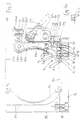
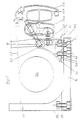
- Figures 1 and 2 represent the prior art for profile mounting elements
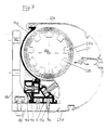
- Figures 3-7 show universal usable profile mounting elements for use with articulated arm awnings, the element according to Figures 3 and 4 and the same thing, just about a vertical axis horizontally Swiveled 180 °
- Figures 5 and 7 show elements with only one slot nut, while the rest are over two times
- 3a shows one Sliding block from Figure 3 in detail.
- 8 and 9 show Profile cross-sections, such as those used in shops or Stand construction are used, with paragraphs according to the invention for sliding blocks and cover slats that are in the grooves of the elements are engaged, or according to Fig. 9 with a screw are held on a sliding block.
- a folding arm awning usually had on a support arm 8 held by connecting screws 19 to a console 18 is bound, which has holes 20 through which the console 18 can be attached to a wall.
- the heart of an articulated arm awning from the prior art and also in the invention is a profile mounting element 1, on the one hand using screws 7 (in the prior art only a screw) is rigidly connected to the support arm 8 and on the other hand Fastening and / or moving elements 2, cover elements 13, facing elements 14, stiffening elements 15 and / or rocker arm joints 16 is able to accommodate.
- the profile mounting elements 1a and 1b according to the prior art were relatively large-volume components for every type of awning were made separately. They were on two points clearly separated from one another with the support arm 8 and / or the console 18.
- the profile mounting element la is with one end 1a1 or with a nose 29 inserted into a groove of the support arm 8a.
- Your main body 1a2 is by a screw 7a, which is screwed into a sliding block 5a is in a recess of the profile mounting element 1a is inserted, screwed to the support arm 8a.
- the upper part 1a3 of the profile mounting element la serves on the one hand as a cover for a space for the cloth shaft 12d and on the other hand as a stiffening element for the main part 1a2 and as an additional part for fastening fasteners 2f.
- the sliding blocks 5 according to the prior art are once - as shown - for fastening the profile mounting element 1 on the support arm 8 and on the other hand for attachment the arm bearing for the swivel arms of the awning (not visible here) used.
- Main part 1b2 is here also over sliding block 5a and screw 7a connected to a shortened support arm 8b.
- the torsional stiffness and rotational stability of the profile mounting element 1b is achieved here in that the upper end 1b3 of the profile mounting element 1b with a second nose at one opposite locking projection 18b1 a bracket 18b set is.
- the inventive 3, 4 and 7 in the profile mounting element 1c different types of awnings are used. It is also here with screws 7 and 5 jewels with the respective Screw arm 8 screwed.
- the profile mounting elements according to the invention 1c are extremely versatile. she draw their torsional stiffness from the fact that two adjacent screw connections with screws 7b are provided and / or that projections 4 as they limit the recesses 3, are provided with paragraphs 9, which engage in opposite recesses of the sliding blocks 5.
- the stiffening element is used 15a for receiving an awning gear 21a, the Wave 29 is indicated schematically.
- the stiffening element 15a is covered by facing element 14b, which on its protruding end 14b1 via a screw 7b and a sliding block 5b3 is connected to the stiffening element 15a.
- Corresponding to parts 14b and 14a is a further facing element 14c provided on the console side of the awning, that in its upper area with a veneer 23a, which is a roof for the retracted awning forms.
- a fastening element 2b is based on the same system via a bearing stone in a groove-shaped recess 3e screwed on. It bears one that is no longer described Deflection arm 26c.
- the structure of the awning according to Fig. 3 corresponds forth the structure of the prior art according to Fig.1.
- the structure according to Figure 4 corresponds in principle to that Structure according to the state of the art Fig. 2 nd are in both Variants according to the invention one and the same profile mounting elements 1c provided.
- the structure is only vertical Axis swiveled through 180 ° and on a shortened support arm 8d mounted directly below the fabric shaft 12a.
- a shortened support arm 8d mounted directly below the fabric shaft 12a.
- Such Recesses in particular if they with projections 4 and Paragraphs 9 are provided by not shown T-nuts and cover surfaces or through aluminum slats, which are simply snapped in, non-positive or positive to be disguised.
- a gear holder 22b is here with a fastening element 2c connected and carries a gear 21b.
- the Fastening element 2c is in part 1c1 and 1c3 of the profile mounting element 1c and an additional one Screw 7b1 and a sliding block 5b1 with the profile mounting element 1c rigidly connected.
- the fasteners 2c and b (Fig.3) stiffen the profile mounting element at the same time.
- the sliding blocks 5 also serve in the same way even a certain stiffening of the element 1, which by appropriate choice of slot length can be varied.
- Fig. 6 The structure according to Fig. 6 is again kept flat. Its profile mounting element 1e is in the upper part 1e3 with a tubular recess 3t provided which is a moving element 2e hinge-like, which with a rocker arm joint 16 is connected. A side slit in the Wall of the upper part 1e3 allows pivoting of the Rocker arm joint 16 in the vertical direction.
- the fastener 2d shown here carries the Auslenkarme 26a and b.
- a facing 23 indicated that the most distant in the extended state Forms part of the cloth shaft 12c and one arranged between them Awning cover 27 spans.
- the main part 1e2 of the profile mounting element 1e is in contrast to the previous ones Examples do not show an open groove, but a tubular one Recess 3u into which a sliding block 5d is inserted is.
- the sliding block 5d is located with its two threaded holes 6 directly over holes in the wall of the main part 1e2 and in the support arm 8f, through which the screws 7d are screwed in.
- the variant according to Figure 6 shows a similar structure as in Figure 5 with the difference that in the main part 1f2 of the profile mounting element 1f again two groove-shaped recesses 3p and 3q are provided and that the upper part 1f3 is not as with Fig.5 with an integral tube recess is, but rather carries a tube 24 through a facing element 14d pressed against the profile mounting element 1f is held.
- the facing element 14d engages on the one hand in a snap-like recess 3r in the upper part 1f3.
- the configuration according to the invention according to FIG. 7 corresponds also the type of an awning according to the state of the Technology Fig. 2.
- three stiffening elements 15b, c and d shown either over the entire length or also connected only in parts to the profile mounting element 1c are.
- the stiffening element 15c is only indicated by dash-dotted lines.
- a facing element 14e protects the fabric shaft 12b against the wall area and carries at the same time a roof-shaped covering 23e.
- the awning cloth 27 is on a piping in a groove of a facing 23d clamped.
- the cloth shaft 12b is made of aluminum and is profiled along its circumference on average by grooves 28, a stiffening while saving weight entail.
- the longitudinal grooves 28 facilitate drying out of one any soaked awning cloth 27. Also serve the grooves 28, especially since they are in the wound state of the cloth 27 channels form the air supply to any electric drive motor. This can then be smaller can be dimensioned and the shaft itself can be used with smaller Diameter - with the same cloth performance.
- Undercut longitudinal grooves 28b also facilitate this Clamp the awning fabric on the shaft side using a Keders or a feather. Allow tapered grooves also the insertion of blocks, sliding blocks or the like., These for fastening purposes, but also for Stiffening can be provided.
- the profile mounting elements also any other cross-sectional shapes such as have rectangular shapes.
- the profile mounting element according to the invention can according to the invention also the fastening of the fabric shaft bearing, the hinge bracket and rail bracket for drop arm and rail awnings to serve; in the latter case especially if the rails are offset asymmetrically or in the middle are.
Landscapes
- Engineering & Computer Science (AREA)
- Architecture (AREA)
- Civil Engineering (AREA)
- Structural Engineering (AREA)
- General Engineering & Computer Science (AREA)
- Mechanical Engineering (AREA)
- Building Awnings And Sunshades (AREA)
- Tents Or Canopies (AREA)
Claims (9)
- Banne, comportant au moins un bras support (8), sur lequel est fixé un élément de montage (1), destiné à recevoir et fixer différents éléments de fixation et/ou cinématiques (2), avec des évidements (3) en forme de rainures et/ou de tubes, destinés à recevoir les éléments de fixation et/ou cinématiques (2), évidements (3) dont l'un est pourvu de saillies (4) ayant en section transversale une forme en bride et loge un patin à rainure (5) présentant un trou taraudé (6) destiné à recevoir une vis (7) servant à la fixation de l'élément de montage (1) sur le bras support (8), caractérisée en ce que l'élément de montage est réalisé sous forme d'élément de montage profilé (1) à section transversale à peu près polygonale, où sur au moins deux côtés du polygone sont réalisés des évidements (3) et le ou les évidement(s) étant réalisé(s) sur un côté du polygone, pour laisser le passage à deux vis de fixation (7) situées l'une à côté de l'autre, dans le patin à rainure (5) étant prévus au moins deux trous taraudés (6) ménagés l'un à côté de l'autre, ou bien où au moins deux évidements (3), placés l'un à côté de l'autre, sont pourvus chacun d'au moins un patin à rainure (5) destiné chacun à au moins une vis (7), et en ce que, en état de fonctionnement, la liaison, transmettant une force de serrage et intervenant entre l'élément de montage profilé (1) et le bras support (8), s'effectue exclusivement par l'intermédiaire des vis (7), et en ce qu'au moins sur un côté du polygone sont ménagés des évidements (3), sur lesquels les saillies (4) du genre de brides présentent des talons (9) tournés vers l'intérieur et destinés à l'engagement dans des évidements (10) - de préférence mutuellement identiques - réalisés dans le patin à rainure (5) respectif.
- Banne selon la revendication 1, caractérisée en ce que la forme polygonale de la section transversale présente des longueurs de côté différentes et en ce que - à l'état monté - la base (11) de la forme polygonale de la section transversale est tournée de préférence vers l'arbre à toile (12) de la banne.
- Banne selon la revendication 2, caractérisée en ce que la base de la forme polygonale de la section transversale qui est voisine de l'arbre à toile est dotée d'une incurvaticn concave et épouse la forme de la périphérie de l'arbre à toile.
- Banne selon l'une des revendications précédentes, caractérisée en ce que l'élément de montage profilé (1) est réalisé avec une forme tubulaire, au moins intérieurement.
- Banne selon l'une des revendications précédentes, caractérisée en ce qu'au moins un évidement (3) est réalisé en forme de charnière et/ou de fermeture à déclic, et sert, le cas échéant, à recevoir des éléments de recouvrement (13), d'occultation-parement (14) ou de rigidification (15).
- Banne selon l'une des revendications précédentes, caractérisée en ce que l'élément de montage profilé présente au moins un perçage longitudinal (3t) qui, en cas de fonctionnement, reçoit au moins un élément cinématique (2e) cylindrique qui agit comme une charnière, la charnière servant de préférence au montage d'une articulation à levier basculant. (figure 6).
- Banne selon l'une des revendications précédentes, caractérisée en ce que l'élément de montage profilé est fabriqué à partir d'un alliage résistant à la corrosion, de préférence façonné par extrusion - par exemple en aluminium - ou fabriqué en tôle selon la technique de formage par roulage et/ou est revêtu par anodisation et/ou d'un revêtement résistant aux intempéries.
- Banne selon l'une des revendications précédentes, caractérisée en ce que tous les évidements (3), ouverts ou non utilisés, sont recouverts à l'aide de lamelles d'aluminium - de préférence susceptibles d'être enfilées ou appliquées par encliquetage -, des rainures étroites étant en particulier prévues à cette fin dans la zone des saillies (4).
- Banne selon l'une des revendications précédentes, caractérisée en ce qu'au moins l'un des évidements (3), le cas échéant un perçage cylindrique, est réalisé pour recevoir un filetage, respectivement une vis, dans la direction longitudinale de l'élément (1).
Applications Claiming Priority (3)
| Application Number | Priority Date | Filing Date | Title |
|---|---|---|---|
| CH8592 | 1992-01-13 | ||
| CH85/92 | 1992-01-13 | ||
| PCT/EP1993/000051 WO1993014283A1 (fr) | 1992-01-13 | 1993-01-12 | Element de montage profile destine a recevoir et a maintenir differents elements de fixation et/ou de deplacement d'un store a bannes |
Publications (2)
| Publication Number | Publication Date |
|---|---|
| EP0623183A1 EP0623183A1 (fr) | 1994-11-09 |
| EP0623183B1 true EP0623183B1 (fr) | 1998-03-25 |
Family
ID=4178928
Family Applications (1)
| Application Number | Title | Priority Date | Filing Date |
|---|---|---|---|
| EP93902176A Expired - Lifetime EP0623183B1 (fr) | 1992-01-13 | 1993-01-12 | Element de montage profile destine a recevoir et a maintenir differents elements de fixation et/ou de deplacement d'un store a bannes |
Country Status (6)
| Country | Link |
|---|---|
| US (1) | US5492162A (fr) |
| EP (1) | EP0623183B1 (fr) |
| AT (1) | ATE164413T1 (fr) |
| CA (1) | CA2128018A1 (fr) |
| DE (1) | DE59308315D1 (fr) |
| WO (1) | WO1993014283A1 (fr) |
Families Citing this family (13)
| Publication number | Priority date | Publication date | Assignee | Title |
|---|---|---|---|---|
| DE9403140U1 (de) * | 1994-02-25 | 1994-05-05 | Stobag Ag Merenschwand | Markise |
| DE19503263B4 (de) * | 1995-02-02 | 2006-05-18 | Müller, Thomas | Markise |
| BE1009550A3 (nl) * | 1995-08-24 | 1997-05-06 | Brutsaert Accessories Nv | Manueel afrolbare luifel. |
| EP0853710B1 (fr) * | 1995-10-06 | 2001-08-01 | Cedis Licensing Gmbh | Marquise |
| DE29612904U1 (de) * | 1996-07-25 | 1996-09-26 | Schmitz-Werke GmbH + Co, 48282 Emsdetten | Gelenkarm-Markise |
| DE29612905U1 (de) * | 1996-07-25 | 1996-10-02 | Schmitz Werke | Gelenkarmmarkise mit Regendach |
| DE10001756A1 (de) * | 2000-01-18 | 2001-07-19 | Schmitz Werke | Gelenkarm-Markise mit einer Abdeckung, insbesondere Kassetten-Markise |
| EP1122377A3 (fr) * | 2000-01-31 | 2003-08-06 | Rödelbronn GmbH | Marquise à caisson |
| US7770625B2 (en) * | 2004-09-17 | 2010-08-10 | Stephen Lukos | Anti-bow roller tube arrangement |
| US8220520B2 (en) * | 2004-09-17 | 2012-07-17 | Stephen Lukos | Spring biased slide arrangement for anti-bow roller tube |
| ES2246738B1 (es) * | 2005-06-10 | 2007-02-16 | Llaza, S.A. | Conjunto de cofre para toldo. |
| US8016016B2 (en) * | 2008-11-07 | 2011-09-13 | Mechoshade Systems, Inc. | Trough shade system and method |
| BE1028223B1 (nl) * | 2020-04-21 | 2021-11-22 | Renson Sunprotection Screens | Een ligger voor een overkapping |
Family Cites Families (11)
| Publication number | Priority date | Publication date | Assignee | Title |
|---|---|---|---|---|
| FR1545852A (fr) * | 1967-09-29 | 1968-11-15 | Perfectionnements aux supports articulés pour dispositifs de stores, tentes et autres | |
| GB1579941A (en) * | 1977-02-03 | 1980-11-26 | Bicc Ltd | Screw fixing |
| DE3001919C2 (de) * | 1980-01-19 | 1984-05-17 | Viktor 7032 Sindelfingen Lohausen | Markise |
| US4469159A (en) * | 1983-09-19 | 1984-09-04 | Viktor Lohausen | Awning |
| US4830531A (en) * | 1985-10-04 | 1989-05-16 | Unistrut International Corp. | Unitary connection assembly for metal channels and method for assembly |
| DE3708155A1 (de) * | 1987-03-13 | 1988-09-22 | Viktor Lohausen | Markise mit zentralem befestigungsprofil |
| DE8802679U1 (de) * | 1988-03-01 | 1988-04-14 | Wörner, Helmut, 7306 Denkendorf | Hohlschiene mit Anklemmvorrichtung |
| DE3820471A1 (de) * | 1988-06-16 | 1989-12-28 | Zeiss Carl Fa | Befestigungseinrichtung fuer ein zielfernrohr |
| DE9000939U1 (de) * | 1990-01-29 | 1990-04-12 | Warema Renkhoff Gmbh & Co Kg, 8772 Marktheidenfeld | Schutzabdeckung für eine Gelenkarm-Markise |
| BE1005703A4 (nl) * | 1991-02-27 | 1993-12-21 | Brutsaert Accessories Nv | Verbeteringen voor een oprolbare luifel. |
| DE4219832C1 (de) * | 1992-06-17 | 1994-01-27 | Mhz Sonnenschutztech Gmbh | Kassettenmarkise |
-
1993
- 1993-01-12 EP EP93902176A patent/EP0623183B1/fr not_active Expired - Lifetime
- 1993-01-12 DE DE59308315T patent/DE59308315D1/de not_active Expired - Fee Related
- 1993-01-12 WO PCT/EP1993/000051 patent/WO1993014283A1/fr not_active Ceased
- 1993-01-12 CA CA002128018A patent/CA2128018A1/fr not_active Abandoned
- 1993-01-12 AT AT93902176T patent/ATE164413T1/de not_active IP Right Cessation
-
1994
- 1994-07-11 US US08/277,986 patent/US5492162A/en not_active Expired - Fee Related
Also Published As
| Publication number | Publication date |
|---|---|
| CA2128018A1 (fr) | 1993-07-22 |
| US5492162A (en) | 1996-02-20 |
| WO1993014283A1 (fr) | 1993-07-22 |
| DE59308315D1 (de) | 1998-04-30 |
| ATE164413T1 (de) | 1998-04-15 |
| EP0623183A1 (fr) | 1994-11-09 |
Similar Documents
| Publication | Publication Date | Title |
|---|---|---|
| AT512283B1 (de) | Solar-montagesystem | |
| DE3342616A1 (de) | Profilrohr fuer die herstellung von leicht montier- und wieder demontierbaren aufbauten | |
| DE102013109845A1 (de) | Lager für eine Unterkonstruktion, beispielsweise einer Terrasse | |
| EP0616088A1 (fr) | Couverture à résille plane ou spatiale, en particulier couverture à résille adaptée à la marche, formée de profiles et de noeuds | |
| EP0623183A1 (fr) | Element de montage profile destine a recevoir et a maintenir differents elements de fixation et/ou de deplacement d'un store a bannes | |
| EP2256432A2 (fr) | Support pour modules solaires carrés | |
| DE3708155A1 (de) | Markise mit zentralem befestigungsprofil | |
| EP0918116B1 (fr) | Equerre de fixation | |
| DE10128748B4 (de) | Fassadenkonstruktion | |
| EP0484741B1 (fr) | Noeud pour treillis | |
| DE102009022780A1 (de) | Ständer für rechteckige Solarmodule | |
| EP0067970B1 (fr) | Dispositif de fixation pour éléments de façade | |
| DE2817759A1 (de) | Gelenkarmmarkise | |
| EP2574702A2 (fr) | Structure de toit ou de mur | |
| DE29710086U1 (de) | Balkonrahmen | |
| DE202011002161U1 (de) | Tragwerksystem | |
| EP0625619B1 (fr) | Plate-forme d'échafaudage | |
| DE8906210U1 (de) | Trägerverbindung | |
| EP0617191B1 (fr) | Dispositif de guidage pour stores de jardins d'hiver | |
| DE102020134445A1 (de) | Tragkonsole mit schwenkbarer Lagerung zur Anbringung eines Gehäuses einer Sonnenschutzanlage | |
| DE9319691U1 (de) | Maueröffnungsschablone | |
| DE202016008379U1 (de) | Nachführbare Trägervorrichtung für Solarmodule mit Sparrenprofilschiene | |
| DE20320097U1 (de) | Zelt | |
| DE2751149C2 (de) | Ecklager für Dreh/Kippflügel, insbesondere für Drehkipp-Fensterflügel | |
| DE202017107484U1 (de) | Tragvorrichtung mit einem Tragarm zum Tragen eines Gegenstandes |
Legal Events
| Date | Code | Title | Description |
|---|---|---|---|
| PUAI | Public reference made under article 153(3) epc to a published international application that has entered the european phase |
Free format text: ORIGINAL CODE: 0009012 |
|
| 17P | Request for examination filed |
Effective date: 19940805 |
|
| AK | Designated contracting states |
Kind code of ref document: A1 Designated state(s): AT BE CH DE DK ES FR GB IT LI NL SE |
|
| RAP1 | Party data changed (applicant data changed or rights of an application transferred) |
Owner name: CEDIS LICENSING GMBH |
|
| 17Q | First examination report despatched |
Effective date: 19960213 |
|
| GRAG | Despatch of communication of intention to grant |
Free format text: ORIGINAL CODE: EPIDOS AGRA |
|
| GRAG | Despatch of communication of intention to grant |
Free format text: ORIGINAL CODE: EPIDOS AGRA |
|
| GRAH | Despatch of communication of intention to grant a patent |
Free format text: ORIGINAL CODE: EPIDOS IGRA |
|
| GRAH | Despatch of communication of intention to grant a patent |
Free format text: ORIGINAL CODE: EPIDOS IGRA |
|
| GRAA | (expected) grant |
Free format text: ORIGINAL CODE: 0009210 |
|
| AK | Designated contracting states |
Kind code of ref document: B1 Designated state(s): AT BE CH DE DK ES FR GB IT LI NL SE |
|
| PG25 | Lapsed in a contracting state [announced via postgrant information from national office to epo] |
Ref country code: IT Free format text: LAPSE BECAUSE OF FAILURE TO SUBMIT A TRANSLATION OF THE DESCRIPTION OR TO PAY THE FEE WITHIN THE PRE;WARNING: LAPSES OF ITALIAN PATENTS WITH EFFECTIVE DATE BEFORE 2007 MAY HAVE OCCURRED AT ANY TIME BEFORE 2007. THE CORRECT EFFECTIVE DATE MAY BE DIFFERENT FROM THE ONE RECORDED.SCRIBED TIME-LIMIT Effective date: 19980325 Ref country code: ES Free format text: THE PATENT HAS BEEN ANNULLED BY A DECISION OF A NATIONAL AUTHORITY Effective date: 19980325 |
|
| REF | Corresponds to: |
Ref document number: 164413 Country of ref document: AT Date of ref document: 19980415 Kind code of ref document: T |
|
| REG | Reference to a national code |
Ref country code: CH Ref legal event code: EP |
|
| REF | Corresponds to: |
Ref document number: 59308315 Country of ref document: DE Date of ref document: 19980430 |
|
| REG | Reference to a national code |
Ref country code: CH Ref legal event code: NV Representative=s name: BUECHEL & PARTNER AG PATENTBUERO |
|
| PG25 | Lapsed in a contracting state [announced via postgrant information from national office to epo] |
Ref country code: SE Free format text: LAPSE BECAUSE OF FAILURE TO SUBMIT A TRANSLATION OF THE DESCRIPTION OR TO PAY THE FEE WITHIN THE PRESCRIBED TIME-LIMIT Effective date: 19980625 Ref country code: DK Free format text: LAPSE BECAUSE OF FAILURE TO SUBMIT A TRANSLATION OF THE DESCRIPTION OR TO PAY THE FEE WITHIN THE PRESCRIBED TIME-LIMIT Effective date: 19980625 |
|
| ET | Fr: translation filed | ||
| GBT | Gb: translation of ep patent filed (gb section 77(6)(a)/1977) |
Effective date: 19980611 |
|
| PGFP | Annual fee paid to national office [announced via postgrant information from national office to epo] |
Ref country code: FR Payment date: 19990118 Year of fee payment: 7 |
|
| PGFP | Annual fee paid to national office [announced via postgrant information from national office to epo] |
Ref country code: AT Payment date: 19990127 Year of fee payment: 7 |
|
| PGFP | Annual fee paid to national office [announced via postgrant information from national office to epo] |
Ref country code: BE Payment date: 19990128 Year of fee payment: 7 |
|
| PLBE | No opposition filed within time limit |
Free format text: ORIGINAL CODE: 0009261 |
|
| STAA | Information on the status of an ep patent application or granted ep patent |
Free format text: STATUS: NO OPPOSITION FILED WITHIN TIME LIMIT |
|
| PG25 | Lapsed in a contracting state [announced via postgrant information from national office to epo] |
Ref country code: LI Free format text: LAPSE BECAUSE OF NON-PAYMENT OF DUE FEES Effective date: 19990131 Ref country code: CH Free format text: LAPSE BECAUSE OF NON-PAYMENT OF DUE FEES Effective date: 19990131 |
|
| 26N | No opposition filed | ||
| REG | Reference to a national code |
Ref country code: CH Ref legal event code: PL |
|
| PGFP | Annual fee paid to national office [announced via postgrant information from national office to epo] |
Ref country code: GB Payment date: 19991221 Year of fee payment: 8 |
|
| PG25 | Lapsed in a contracting state [announced via postgrant information from national office to epo] |
Ref country code: AT Free format text: LAPSE BECAUSE OF NON-PAYMENT OF DUE FEES Effective date: 20000112 |
|
| PGFP | Annual fee paid to national office [announced via postgrant information from national office to epo] |
Ref country code: NL Payment date: 20000128 Year of fee payment: 8 |
|
| PG25 | Lapsed in a contracting state [announced via postgrant information from national office to epo] |
Ref country code: BE Free format text: LAPSE BECAUSE OF NON-PAYMENT OF DUE FEES Effective date: 20000131 |
|
| PGFP | Annual fee paid to national office [announced via postgrant information from national office to epo] |
Ref country code: DE Payment date: 20000619 Year of fee payment: 8 |
|
| BERE | Be: lapsed |
Owner name: CEDIS LICENSING G.M.B.H. Effective date: 20000131 |
|
| PG25 | Lapsed in a contracting state [announced via postgrant information from national office to epo] |
Ref country code: FR Free format text: LAPSE BECAUSE OF NON-PAYMENT OF DUE FEES Effective date: 20000929 |
|
| REG | Reference to a national code |
Ref country code: FR Ref legal event code: ST |
|
| PG25 | Lapsed in a contracting state [announced via postgrant information from national office to epo] |
Ref country code: GB Free format text: LAPSE BECAUSE OF NON-PAYMENT OF DUE FEES Effective date: 20010112 |
|
| PG25 | Lapsed in a contracting state [announced via postgrant information from national office to epo] |
Ref country code: NL Free format text: LAPSE BECAUSE OF NON-PAYMENT OF DUE FEES Effective date: 20010801 |
|
| GBPC | Gb: european patent ceased through non-payment of renewal fee |
Effective date: 20010112 |
|
| NLV4 | Nl: lapsed or anulled due to non-payment of the annual fee |
Effective date: 20010801 |
|
| PG25 | Lapsed in a contracting state [announced via postgrant information from national office to epo] |
Ref country code: DE Free format text: LAPSE BECAUSE OF NON-PAYMENT OF DUE FEES Effective date: 20011101 |