EP2574702A2 - Structure de toit ou de mur - Google Patents
Structure de toit ou de mur Download PDFInfo
- Publication number
- EP2574702A2 EP2574702A2 EP12185516A EP12185516A EP2574702A2 EP 2574702 A2 EP2574702 A2 EP 2574702A2 EP 12185516 A EP12185516 A EP 12185516A EP 12185516 A EP12185516 A EP 12185516A EP 2574702 A2 EP2574702 A2 EP 2574702A2
- Authority
- EP
- European Patent Office
- Prior art keywords
- roof
- strut
- holder
- wall construction
- main
- Prior art date
- Legal status (The legal status is an assumption and is not a legal conclusion. Google has not performed a legal analysis and makes no representation as to the accuracy of the status listed.)
- Granted
Links
Images


Classifications
-
- E—FIXED CONSTRUCTIONS
- E04—BUILDING
- E04B—GENERAL BUILDING CONSTRUCTIONS; WALLS, e.g. PARTITIONS; ROOFS; FLOORS; CEILINGS; INSULATION OR OTHER PROTECTION OF BUILDINGS
- E04B7/00—Roofs; Roof construction with regard to insulation
- E04B7/02—Roofs; Roof construction with regard to insulation with plane sloping surfaces, e.g. saddle roofs
- E04B7/022—Roofs; Roof construction with regard to insulation with plane sloping surfaces, e.g. saddle roofs consisting of a plurality of parallel similar trusses or portal frames
- E04B7/024—Roofs; Roof construction with regard to insulation with plane sloping surfaces, e.g. saddle roofs consisting of a plurality of parallel similar trusses or portal frames the trusses or frames supporting load-bearing purlins, e.g. braced purlins
-
- E—FIXED CONSTRUCTIONS
- E04—BUILDING
- E04B—GENERAL BUILDING CONSTRUCTIONS; WALLS, e.g. PARTITIONS; ROOFS; FLOORS; CEILINGS; INSULATION OR OTHER PROTECTION OF BUILDINGS
- E04B1/00—Constructions in general; Structures which are not restricted either to walls, e.g. partitions, or floors or ceilings or roofs
- E04B1/18—Structures comprising elongated load-supporting parts, e.g. columns, girders, skeletons
- E04B1/24—Structures comprising elongated load-supporting parts, e.g. columns, girders, skeletons the supporting parts consisting of metal
- E04B1/2403—Connection details of the elongated load-supporting parts
- E04B2001/2451—Connections between closed section profiles
-
- E—FIXED CONSTRUCTIONS
- E04—BUILDING
- E04B—GENERAL BUILDING CONSTRUCTIONS; WALLS, e.g. PARTITIONS; ROOFS; FLOORS; CEILINGS; INSULATION OR OTHER PROTECTION OF BUILDINGS
- E04B1/00—Constructions in general; Structures which are not restricted either to walls, e.g. partitions, or floors or ceilings or roofs
- E04B1/18—Structures comprising elongated load-supporting parts, e.g. columns, girders, skeletons
- E04B1/24—Structures comprising elongated load-supporting parts, e.g. columns, girders, skeletons the supporting parts consisting of metal
- E04B1/2403—Connection details of the elongated load-supporting parts
- E04B2001/2457—Beam to beam connections
-
- E—FIXED CONSTRUCTIONS
- E04—BUILDING
- E04B—GENERAL BUILDING CONSTRUCTIONS; WALLS, e.g. PARTITIONS; ROOFS; FLOORS; CEILINGS; INSULATION OR OTHER PROTECTION OF BUILDINGS
- E04B1/00—Constructions in general; Structures which are not restricted either to walls, e.g. partitions, or floors or ceilings or roofs
- E04B1/18—Structures comprising elongated load-supporting parts, e.g. columns, girders, skeletons
- E04B1/24—Structures comprising elongated load-supporting parts, e.g. columns, girders, skeletons the supporting parts consisting of metal
- E04B2001/2466—Details of the elongated load-supporting parts
-
- E—FIXED CONSTRUCTIONS
- E04—BUILDING
- E04B—GENERAL BUILDING CONSTRUCTIONS; WALLS, e.g. PARTITIONS; ROOFS; FLOORS; CEILINGS; INSULATION OR OTHER PROTECTION OF BUILDINGS
- E04B1/00—Constructions in general; Structures which are not restricted either to walls, e.g. partitions, or floors or ceilings or roofs
- E04B1/18—Structures comprising elongated load-supporting parts, e.g. columns, girders, skeletons
- E04B1/24—Structures comprising elongated load-supporting parts, e.g. columns, girders, skeletons the supporting parts consisting of metal
- E04B2001/2487—Portico type structures
-
- E—FIXED CONSTRUCTIONS
- E04—BUILDING
- E04C—STRUCTURAL ELEMENTS; BUILDING MATERIALS
- E04C3/00—Structural elongated elements designed for load-supporting
- E04C3/02—Joists; Girders, trusses, or trusslike structures, e.g. prefabricated; Lintels; Transoms; Braces
- E04C3/04—Joists; Girders, trusses, or trusslike structures, e.g. prefabricated; Lintels; Transoms; Braces of metal
- E04C2003/0404—Joists; Girders, trusses, or trusslike structures, e.g. prefabricated; Lintels; Transoms; Braces of metal beams, girders, or joists characterised by cross-sectional aspects
- E04C2003/0426—Joists; Girders, trusses, or trusslike structures, e.g. prefabricated; Lintels; Transoms; Braces of metal beams, girders, or joists characterised by cross-sectional aspects characterised by material distribution in cross section
- E04C2003/0439—Joists; Girders, trusses, or trusslike structures, e.g. prefabricated; Lintels; Transoms; Braces of metal beams, girders, or joists characterised by cross-sectional aspects characterised by material distribution in cross section the cross-section comprising open parts and hollow parts
-
- E—FIXED CONSTRUCTIONS
- E04—BUILDING
- E04C—STRUCTURAL ELEMENTS; BUILDING MATERIALS
- E04C3/00—Structural elongated elements designed for load-supporting
- E04C3/02—Joists; Girders, trusses, or trusslike structures, e.g. prefabricated; Lintels; Transoms; Braces
- E04C3/04—Joists; Girders, trusses, or trusslike structures, e.g. prefabricated; Lintels; Transoms; Braces of metal
- E04C2003/0404—Joists; Girders, trusses, or trusslike structures, e.g. prefabricated; Lintels; Transoms; Braces of metal beams, girders, or joists characterised by cross-sectional aspects
- E04C2003/0443—Joists; Girders, trusses, or trusslike structures, e.g. prefabricated; Lintels; Transoms; Braces of metal beams, girders, or joists characterised by cross-sectional aspects characterised by substantial shape of the cross-section
- E04C2003/0465—Joists; Girders, trusses, or trusslike structures, e.g. prefabricated; Lintels; Transoms; Braces of metal beams, girders, or joists characterised by cross-sectional aspects characterised by substantial shape of the cross-section square- or rectangular-shaped
-
- E—FIXED CONSTRUCTIONS
- E04—BUILDING
- E04H—BUILDINGS OR LIKE STRUCTURES FOR PARTICULAR PURPOSES; SWIMMING OR SPLASH BATHS OR POOLS; MASTS; FENCING; TENTS OR CANOPIES, IN GENERAL
- E04H15/00—Tents or canopies, in general
Definitions
- the invention relates to a roof or wall construction, in particular for a reusable hall or a reusable tent.
- a scaffold-like wall or roof construction is used in halls and tents with relatively little effort for event purposes, for storage purposes and industrial purposes use. It gives the building structure and can be used for attaching walls, such as a tarpaulin or a metal skin.
- a generic roof or wall construction has at least one main strut extending in a first extension direction and at least one transverse strut attached at least indirectly to the main strut, which extends in a second extension direction deviating from the first extension direction, preferably enclosing it at a right angle ,
- at least one attachment device for fastening a fastened to the cross member or hereby integrally connected holder is provided on an outer side of the main strut.
- the main struts can form vertical beams, which are connected to each other by means of the then horizontally oriented cross braces.
- the main struts are preferably part of a roof truss usually comprising two main struts, whose two main struts are connected to one another in the region of a roof ridge.
- each other standing main struts and cross struts are firmly connected to each other for the stated purpose. This is currently usually done by means of screw that connect the holder with the main carrier.
- the main strut may have mounting holes, in which screws or bolts are inserted, which also extend through an end-side retaining plate of the holder of the transverse strut.
- Also constructions are known in which welded to the main strut U-shaped mounting bracket are provided, to which the cross braces can be screwed.
- the object of the invention is therefore to provide a generic roof or wall construction available, which allows the attachment of the cross member to the main strut in a simple manner.
- attachment device two extending in the first direction of extension Support webs with mutually facing support surfaces on both sides of a fixing region through which the at least partially arranged in the fixing region holder of the cross strut is fixed in position at least transversely to the first direction of extension of the main strut.
- a fixing area is defined directly on the main strut by means of two support surfaces extending in the first extension direction and thus parallel to one another, which are preferably an integral part of the main body of the main strut.
- the holder is arranged, which is limited in movement by this arrangement in view of its relative movement relative to the main strut, at least in a direction orthogonal to both directions of extension.
- That portion of the holder which is arranged in the fixing area bounded by the support surfaces preferably has external dimensions which limit the relative mobility of the holder relative to the main bar orthogonal to the two extension directions, preferably to a maximum of 10 mm.
- the opposite support surface facing each other but need not be completely aligned parallel to each other.
- the said support surfaces do not yet create a complete connection between the holder and the main strut. However, along with other measures described below, they provide a very simple and complete connection method that is flexible and inexpensive. However, provided on the main strut and by the support surface bounding fixing area may also be useful if in a conventional manner, the connection between the main struts and the holders by means of screws or the like. In such a case, the fixing areas are a valuable assembly aid since they facilitate the positioning of the holders.
- the roof or wall construction not only each have a main strut and cross member, but each has a plurality at least partially mutually parallel main struts and a plurality of parallel cross struts, the cross struts connecting two main struts together.
- the main struts can be full profiles.
- hollow profiles made of metal, in particular of steel or aluminum, are preferred. These can be produced in a simple manner in continuous profile production processes, such as, for example, by continuous casting, wherein the support webs with the support bearing surfaces can also be an immediate part of such a hollow profile.
- At least one of the support webs is attached to the outside of the main strut in alignment with an intermediate wall provided within the hollow profile.
- This intermediate wall separates the inner region of the hollow profile into at least two partial chambers. Because this intermediate wall is arranged within the hollow profile where a support surface is located on the outside of the hollow profile, the forces introduced here from the outside into the main strut can be supported in a particularly advantageous manner while avoiding unwanted strong deformation of the main strut.
- Under the said alignment is understood in the context of the invention that the support web and the inner wall are offset from one another by not more than 5 mm.
- the support webs has a piping groove for receiving a welt.
- the support bridge in question thus fulfills a dual function. To the he limited in the manner described, the mobility of the holder of the crossbar. On the other hand, the carrier of the Kedernut, which is thus arranged outside of the hollow profile. In hollow profiles typically used in the case of generic roof or wall constructions with walls which define a rectangular cross section, the piping groove is thus provided outside this cross section.
- the aforementioned shape with the fixing area which is limited by support surfaces on both sides, as mentioned above, taken alone does not lead to a complete fixing of the holder on the main carrier.
- the shaping may be in the manner explained below, wherein other possibilities are also encompassed by the invention.
- At least one of the support surfaces is provided at the bottom of a retaining surface bounded on both sides by retaining surfaces into which the holder is at least partially inserted and which thereby counteracts a separation of the holder from the main strut in the direction of the second extension direction.
- an undercut is caused by the said retaining groove, which counteracts a separation of the transverse strut from the main strut at least until the holder has been pulled out of the retaining groove. Due to the opposite second support surface, however, this is not possible without tilting the main strut and the crossbar against each other.
- a retaining groove in the region of both support surfaces.
- it is preferably the top of the two support surfaces in the erected state of the roof or wall construction, so that after inserting the holder into the groove, the main strut and the cross member can already be handled together the weight of the crossbar together with the second support surface counteracts an escape of the holder from the holding groove.
- it can also be advantageous configurations with two-sided holding, in which a displacement of the holder relative to the main strut after assembly only in the direction of extension of the main strut is possible.
- the retaining groove is preferably formed by walls which are an integral part of a main body of the main strut, in particular a one-piece part of a hollow profile. It is therefore preferably walls, which are already provided in the production of the profile and which extend over the entire length of the profile in the extension direction.
- a very simple design of the retaining groove provides that on the outer side of the main strut, for example, an L-shaped profile section is provided which, together with an outer side of the main strut in Fixing area forms the said retaining groove.
- an outer side of a wall of the above-described piping groove forms one of the side surfaces of the retaining groove.
- the trained as an open hollow profile wall of the Kedernut is such part of the side bar that it projects beyond the fixing area and thus forms the closed on three sides holding groove.
- the walls of the Kedernut thus assume a dual function. Also, this provides the advantage that the piping groove is still easily accessible even with already mounted cross braces, since the holder does not affect the access to Kedernut.
- any relative mobility of the main strut and the transverse strut orthogonal to the first direction of extent is prevented.
- a related positive coupling between the main strut and the cross member is considered advantageous, preferably a coupling, which is produced by said tilting movement.
- the attachment device and the holder have cooperating positive engagement means by which the mobility of the holder is limited in the direction of the first direction of extent, when the holder is arranged between the support webs.
- the attachment means between the webs recesses or projections which cooperate with projections or depressions on the holder, in particular on a base plate of the holder, in the manner mentioned.
- At least one of the support webs has at least one point of interruption, wherein a securing portion of the holder extends in the mounted position in this point of interruption, so that the mobility of the holder in the direction of the first direction of extent is limited thereby.
- the arrangement of the interruption position defines at the respective support web, where the cross strut can be attached to the main strut.
- An interruption point of the type mentioned is also subsequently very easy to bring into the respective support web, so that in a simple way new mounting positions for the cross member with respect to the main strut can be created. While this often requires the introduction of new holes in the main strut in known systems and this can lead to an unwanted weakening of the main strut, the introduction of new interruption points in the support web is not accompanied by a deterioration of the stability of the main strut.
- Particularly advantageous is the arrangement of the interruption points in a support web, which is provided on the side of the fixing area facing the center of gravity of the cross section. The closer the weakening is to the center of gravity of the profile, the lower the weakening effect.
- the holder has a base plate, which is arranged in the fixing area and aligned parallel to the outside of the main strut.
- This base plate is in terms of their dimensions adapted to the distance of the support surfaces to each other. Their thickness is preferably adapted to the width of the retaining groove.
- the retaining groove is preferably slightly wider compared to the thickness of the base plate.
- the holder may be integrally connected to the transverse strut, for example welded thereto.
- the separability of the holder of the crossbar is in terms of assembly / disassembly of advantage. It makes it possible to first bring the holder with said pivoting movement into its desired position relative to the main strut in order to connect it to the cross strut only subsequently. This is a considerable advantage during assembly, since otherwise the required pivoting movement would be required in the case of two main struts, which are connected by a cross strut respectively by means of a holder, after attachment of the cross member by means of the first holder on the first main strut the Make connection with the second holder in that the main struts are pivoted against each other.
- main strut attachment means for attaching two pointing in opposite directions cross struts are provided. In this way, a plurality of main struts can be interconnected by mutually aligned transverse struts.
- a main strut with a total of four attachment means is provided, which are preferably arranged mirror-symmetrically relative to the cross section of the main strut to two axes.
- the cross strut may be advantageous to connect the cross strut with the main strut additionally via a support strut. This creates on said holder over another connection between the crossbar and main strut.
- the support strut is connected by means of the further attachment means with the main strut.
- On the opposite side of the support strut is preferably connected by one of said bolts or one of said screws with the crossbar.
- the main strut is preferably a part of a roof truss of the roof structure, while the cross strut forms a purlin of the roof structure.
- this preferably has two main struts, each forming vertically aligned support, which are interconnected by the transverse strut, which in turn is horizontally aligned.
- FIG. 1 shows a construction according to the invention of a hall or tent building. This has a roof construction 10 and wall constructions 8.
- the roof construction 10 has roof trusses 16 as main components, which comprise two main struts 20 each extending from the eaves 12 to the ridge 14 and which are connected to each other via a plurality of roof purlins 50.
- the wall constructions 8 are otherwise constructed in the same way as the roof construction 10 with a modified arrangement and alignment with vertical supports 8a and connecting transverse struts 8b. All further embodiments therefore relate equally to a roof construction 10 as well as the wall constructions 8.
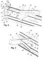
- FIG. 2 and 4 illustrate the attachment of the transverse struts forming roof purlins 50 on the main struts 20th
- the main struts 20 are formed as hollow profiles. They have an approximately rectangular main portion 22 which comprises a total of five hollow chambers 26 separated from one another by intermediate walls 24. At the upper and at the lower end of the main portion 22 each outwardly facing support webs 28 are provided, at the end remote from the main portion 22 slotted hollow sections 30 are provided which each surround a Kedernut 32. Between the provided at the upper end and at the lower end of the main portion 22 supporting webs 28 each have two further support webs 34 are arranged. These aligned to an intermediate wall 24 of the main portion 22 extending support webs 34 define together with the respective outer Support webs 28 fixing areas 36, which serve indirectly the attachment of the Dachpfetten 50.
- holder 70 This is done primarily by means of in the Fig. 4 separately shown holder 70.
- These holders 70 have a base plate 72, from which parallel to each other two fastening extensions 74 extend outward, between which the respective Dachpfette 50 can be fastened.
- the base plates 72 are each arranged in the fixing area 36.
- the mobility of the base plate 72 in the fixing region 36 is limited by supporting surfaces 28a, 34a pointing in the direction of the fixing region 36 on the support webs 28, 34. Furthermore, the base plate 72 extends into a retaining groove 38, at the bottom of the support surface 28a is provided. The side surfaces of this groove 28 are formed by an outer side 22a of the main body 22 and an outer side 30a of the slotted Keder hollow profile 30 partially overlapping the fixing region 36. Due to the arrangement of the base plate 72 within the retaining groove 38, the holder 70 can not be separated from the main strut 20 without tilting in the direction of extension 4 of the roof purlins 50.
- a retainer 70 inserted into the strut 20 remains securely in position during the assembly process.
- break points 34 b are provided in the support web.
- the base plate 72 has projections 72a which extend into these interruption points 34b. In the in the FIGS. 2 and 3 shown position, the holder 70 is therefore held form-fitting by a shift in the direction of extension 2.
- the connection between the holder 70 and the Dachpfette 50 is realized by two screws or bolts 68 which project through holes 74a in the extensions 74 and by corresponding holes in the Dachpfette 50.
- the base plate 72 facing away from the bolt 68 also serves in FIG. 3 apparent manner, the attachment of an optional support strut 90, which at its end facing away from the bolt 68 also has a base plate 92 which is used in a similar manner as the base plate 72 of the holder 70 in a Festlegungs Scheme 36 of the main strut 20.
- FIG. 5 illustrates again the arrangement of the holder 70 and in particular of its base plate 72 in the Festlegungs Scheme 36 of the strut 20. Here it is well seen that the upper end of the base plate 72 is received in the retaining groove 38.
- FIG. 5 is also illustrated by dashed lines, as the holder 70 is inserted into the Festlegungs Symposium 36. For this purpose, it is attached angled in the manner outlined, in order subsequently to be inserted deeper into the retaining groove 38 while the pivoting movement is simultaneous. During this pivoting movement, the positive coupling of the holder 70 with the main strut 20 in the region of the interruption points 34b and the extensions 72a takes place.
- the described type of connection between the holder 70 and the main strut 20 is very easy to implement. However, it is also very stable when two mutually facing holder 70 are connected to adjacent main struts 20 together by a Dachpfette 50. Since the connecting roof purlin 50 any tilting movement of the holder 70 in the sense of FIG.
- roof purlins 50 may then also serve for attaching other components, such as a metal skin for the hall. In the present case, however, it is advantageous if in the also in FIG. 5 illustrated by dotted lines manner a tarpaulin 40 with marginal piping 42 is used.
Landscapes
- Engineering & Computer Science (AREA)
- Architecture (AREA)
- Physics & Mathematics (AREA)
- Electromagnetism (AREA)
- Civil Engineering (AREA)
- Structural Engineering (AREA)
- Tents Or Canopies (AREA)
Priority Applications (1)
| Application Number | Priority Date | Filing Date | Title |
|---|---|---|---|
| SI201230586A SI2574702T1 (sl) | 2011-09-28 | 2012-09-21 | Strešna ali stenska konstrukcija |
Applications Claiming Priority (1)
| Application Number | Priority Date | Filing Date | Title |
|---|---|---|---|
| DE201110083638 DE102011083638A1 (de) | 2011-09-28 | 2011-09-28 | Dach- oder Wandkonstruktion |
Publications (3)
| Publication Number | Publication Date |
|---|---|
| EP2574702A2 true EP2574702A2 (fr) | 2013-04-03 |
| EP2574702A3 EP2574702A3 (fr) | 2013-11-27 |
| EP2574702B1 EP2574702B1 (fr) | 2016-03-16 |
Family
ID=46940363
Family Applications (1)
| Application Number | Title | Priority Date | Filing Date |
|---|---|---|---|
| EP12185516.7A Active EP2574702B1 (fr) | 2011-09-28 | 2012-09-21 | Structure de toit ou de mur |
Country Status (5)
| Country | Link |
|---|---|
| EP (1) | EP2574702B1 (fr) |
| DE (1) | DE102011083638A1 (fr) |
| ES (1) | ES2568690T3 (fr) |
| PL (1) | PL2574702T3 (fr) |
| SI (1) | SI2574702T1 (fr) |
Cited By (1)
| Publication number | Priority date | Publication date | Assignee | Title |
|---|---|---|---|---|
| FR3049632A1 (fr) * | 2016-04-04 | 2017-10-06 | Spaciotempo | Systeme d’attache d’une panne de structure de batiment demontable |
Families Citing this family (2)
| Publication number | Priority date | Publication date | Assignee | Title |
|---|---|---|---|---|
| EP2907941B1 (fr) | 2013-10-01 | 2026-04-29 | Herchenbach Industrial Buildings GmbH | Tente industrielle améliorée |
| DE202016004338U1 (de) | 2016-07-15 | 2017-10-18 | Herchenbach Industrie-Zeltebau Gmbh | Verbessertes Industriezelt und Planenverbund |
Family Cites Families (6)
| Publication number | Priority date | Publication date | Assignee | Title |
|---|---|---|---|---|
| GB1088995A (en) * | 1963-10-25 | 1967-10-25 | Raffaele Biffani | Structural member for building construction |
| US3798865A (en) * | 1972-03-17 | 1974-03-26 | Integrated Ceilings Inc | Grid support structure and clip means therefor |
| DE3027628A1 (de) * | 1980-07-21 | 1982-02-11 | Edwin 6470 Büdingen Röder | Ausbildung von dachbindern und deren verbindung mit pfetten zur erstellung von geruesten von metallzelten und -hallen, insbes. aus leichtmetall |
| US5572844A (en) * | 1995-04-24 | 1996-11-12 | Armstrong World Industries, Inc. | Runner-trim connector |
| CA2250056A1 (fr) * | 1997-01-24 | 1998-07-30 | Teestruct Manufacturing Inc. | Elements et structures de construction rigides et moyens de retenue servant a fixer des feuilles sur ces elements et sur ces structures |
| DE10028401A1 (de) * | 2000-06-13 | 2002-01-10 | Gradinger Hallen Gmbh & Co Kg | Gebäude |
-
2011
- 2011-09-28 DE DE201110083638 patent/DE102011083638A1/de not_active Withdrawn
-
2012
- 2012-09-21 ES ES12185516.7T patent/ES2568690T3/es active Active
- 2012-09-21 EP EP12185516.7A patent/EP2574702B1/fr active Active
- 2012-09-21 SI SI201230586A patent/SI2574702T1/sl unknown
- 2012-09-21 PL PL12185516.7T patent/PL2574702T3/pl unknown
Non-Patent Citations (1)
| Title |
|---|
| None |
Cited By (2)
| Publication number | Priority date | Publication date | Assignee | Title |
|---|---|---|---|---|
| FR3049632A1 (fr) * | 2016-04-04 | 2017-10-06 | Spaciotempo | Systeme d’attache d’une panne de structure de batiment demontable |
| EP3228772A1 (fr) * | 2016-04-04 | 2017-10-11 | Spaciotempo | Structure démontable pour bâtiment de type métallo-textile |
Also Published As
| Publication number | Publication date |
|---|---|
| SI2574702T1 (sl) | 2016-07-29 |
| EP2574702A3 (fr) | 2013-11-27 |
| DE102011083638A1 (de) | 2013-03-28 |
| DE102011083638A8 (de) | 2013-06-06 |
| ES2568690T3 (es) | 2016-05-03 |
| PL2574702T3 (pl) | 2016-09-30 |
| EP2574702B1 (fr) | 2016-03-16 |
Similar Documents
| Publication | Publication Date | Title |
|---|---|---|
| EP3721028B1 (fr) | Équipement comprenant un dispositif anti-soulèvement et procédé pour empêcher un plancher d'échafaudage de se soulever | |
| EP1987213B1 (fr) | Systeme de coffrage de plafond | |
| EP3697983B1 (fr) | Étai destiné à étayer une zone de construction | |
| DE3736553A1 (de) | Wandverbindungsteil | |
| EP3927914B1 (fr) | Élément de coffrage et système modulaire de coffrage | |
| DE10344201A1 (de) | Solarmodulbefestigung, Verfahren zum Montieren einer Solaranlage und Anordnung aus einem Solarmodul und einem Solarmodulrahmen | |
| WO2020049374A1 (fr) | Ferrure d'ajustage et système de support pour modules solaires | |
| EP3529430B1 (fr) | Montant pour une construction à montant et traverse | |
| EP2499311B1 (fr) | Grille de protection latérale et système de protection latérale | |
| DE202012008950U1 (de) | Tragstruktur für ein Terrassendach | |
| EP2574702B1 (fr) | Structure de toit ou de mur | |
| EP3147424A2 (fr) | Support de grille et systeme de support de grille, en particulier pour utilisation universelle dans un echafaudage de protection ou de travail connu | |
| DE102019108036A1 (de) | Überdachungssystem sowie Trägermodul hierfür | |
| DE202006003836U1 (de) | Deckenschalungssystem | |
| EP3101190B1 (fr) | Module de paroi de séparation d'une paroi de séparation | |
| DE69602609T2 (de) | Konstruktionssystem von kaltgeformten teilen mit regelmässig gewellten rändern, und verbindungs- und befestigungselementen in zusammenhang mit diesen | |
| EP0596207A1 (fr) | Profilé en tôle mince, de préférence laminé à froid, pour la construction d'ossatures de support, de tribunes ou semblables | |
| DE202011108692U1 (de) | Hohlprofil und Hallengerüst mit einem solchen Profil | |
| EP2711482B1 (fr) | Dispositif de fixation pour l'ancrage d'un échafaudage | |
| EP4279677B1 (fr) | Joint de mur | |
| DE2250505C3 (de) | Raumzelle für Bauwerke | |
| EP0818592A1 (fr) | Système d'armature | |
| DE102021210759B4 (de) | Schutzzaunsystem und Verfahren zum Montieren eines Schutzzaunsystems | |
| DE202011050816U1 (de) | Halbrahmen für Dreigelenkrahmen in Verbundbauweise | |
| DE2711403C2 (de) | Deckentragwerk |
Legal Events
| Date | Code | Title | Description |
|---|---|---|---|
| PUAI | Public reference made under article 153(3) epc to a published international application that has entered the european phase |
Free format text: ORIGINAL CODE: 0009012 |
|
| AK | Designated contracting states |
Kind code of ref document: A2 Designated state(s): AL AT BE BG CH CY CZ DE DK EE ES FI FR GB GR HR HU IE IS IT LI LT LU LV MC MK MT NL NO PL PT RO RS SE SI SK SM TR |
|
| AX | Request for extension of the european patent |
Extension state: BA ME |
|
| PUAL | Search report despatched |
Free format text: ORIGINAL CODE: 0009013 |
|
| AK | Designated contracting states |
Kind code of ref document: A3 Designated state(s): AL AT BE BG CH CY CZ DE DK EE ES FI FR GB GR HR HU IE IS IT LI LT LU LV MC MK MT NL NO PL PT RO RS SE SI SK SM TR |
|
| AX | Request for extension of the european patent |
Extension state: BA ME |
|
| RIC1 | Information provided on ipc code assigned before grant |
Ipc: E04B 7/02 20060101ALI20131024BHEP Ipc: E04B 1/342 20060101ALI20131024BHEP Ipc: E04H 15/18 20060101ALI20131024BHEP Ipc: E04H 15/00 20060101ALN20131024BHEP Ipc: E04B 1/24 20060101AFI20131024BHEP |
|
| 17P | Request for examination filed |
Effective date: 20140331 |
|
| RAX | Requested extension states of the european patent have changed |
Extension state: BA Payment date: 20140331 Extension state: ME Payment date: 20140331 |
|
| RBV | Designated contracting states (corrected) |
Designated state(s): AL AT BE BG CH CY CZ DE DK EE ES FI FR GB GR HR HU IE IS IT LI LT LU LV MC MK MT NL NO PL PT RO RS SE SI SK SM TR |
|
| RIN1 | Information on inventor provided before grant (corrected) |
Inventor name: ARNDT, DOMENICO Inventor name: SPECK, MARKUS WILHELM |
|
| GRAP | Despatch of communication of intention to grant a patent |
Free format text: ORIGINAL CODE: EPIDOSNIGR1 |
|
| RIC1 | Information provided on ipc code assigned before grant |
Ipc: E04H 15/18 20060101ALI20151002BHEP Ipc: E04H 15/00 20060101ALN20151002BHEP Ipc: E04B 7/02 20060101ALI20151002BHEP Ipc: E04B 1/342 20060101ALI20151002BHEP Ipc: E04B 1/24 20060101AFI20151002BHEP |
|
| INTG | Intention to grant announced |
Effective date: 20151026 |
|
| GRAS | Grant fee paid |
Free format text: ORIGINAL CODE: EPIDOSNIGR3 |
|
| GRAA | (expected) grant |
Free format text: ORIGINAL CODE: 0009210 |
|
| RIN1 | Information on inventor provided before grant (corrected) |
Inventor name: ARNDT, DOMENICO Inventor name: SPECK, MARKUS WILHELM |
|
| AK | Designated contracting states |
Kind code of ref document: B1 Designated state(s): AL AT BE BG CH CY CZ DE DK EE ES FI FR GB GR HR HU IE IS IT LI LT LU LV MC MK MT NL NO PL PT RO RS SE SI SK SM TR |
|
| AX | Request for extension of the european patent |
Extension state: BA ME |
|
| REG | Reference to a national code |
Ref country code: GB Ref legal event code: FG4D Free format text: NOT ENGLISH |
|
| REG | Reference to a national code |
Ref country code: CH Ref legal event code: EP Ref country code: CH Ref legal event code: NV Representative=s name: DR. LUSUARDI AG, CH |
|
| REG | Reference to a national code |
Ref country code: IE Ref legal event code: FG4D Free format text: LANGUAGE OF EP DOCUMENT: GERMAN |
|
| REG | Reference to a national code |
Ref country code: AT Ref legal event code: REF Ref document number: 781400 Country of ref document: AT Kind code of ref document: T Effective date: 20160415 |
|
| REG | Reference to a national code |
Ref country code: DE Ref legal event code: R096 Ref document number: 502012006274 Country of ref document: DE |
|
| REG | Reference to a national code |
Ref country code: ES Ref legal event code: FG2A Ref document number: 2568690 Country of ref document: ES Kind code of ref document: T3 Effective date: 20160503 |
|
| REG | Reference to a national code |
Ref country code: NL Ref legal event code: FP |
|
| REG | Reference to a national code |
Ref country code: LT Ref legal event code: MG4D |
|
| PG25 | Lapsed in a contracting state [announced via postgrant information from national office to epo] |
Ref country code: HR Free format text: LAPSE BECAUSE OF FAILURE TO SUBMIT A TRANSLATION OF THE DESCRIPTION OR TO PAY THE FEE WITHIN THE PRESCRIBED TIME-LIMIT Effective date: 20160316 Ref country code: GR Free format text: LAPSE BECAUSE OF FAILURE TO SUBMIT A TRANSLATION OF THE DESCRIPTION OR TO PAY THE FEE WITHIN THE PRESCRIBED TIME-LIMIT Effective date: 20160617 Ref country code: NO Free format text: LAPSE BECAUSE OF FAILURE TO SUBMIT A TRANSLATION OF THE DESCRIPTION OR TO PAY THE FEE WITHIN THE PRESCRIBED TIME-LIMIT Effective date: 20160616 Ref country code: FI Free format text: LAPSE BECAUSE OF FAILURE TO SUBMIT A TRANSLATION OF THE DESCRIPTION OR TO PAY THE FEE WITHIN THE PRESCRIBED TIME-LIMIT Effective date: 20160316 |
|
| PG25 | Lapsed in a contracting state [announced via postgrant information from national office to epo] |
Ref country code: RS Free format text: LAPSE BECAUSE OF FAILURE TO SUBMIT A TRANSLATION OF THE DESCRIPTION OR TO PAY THE FEE WITHIN THE PRESCRIBED TIME-LIMIT Effective date: 20160316 Ref country code: LT Free format text: LAPSE BECAUSE OF FAILURE TO SUBMIT A TRANSLATION OF THE DESCRIPTION OR TO PAY THE FEE WITHIN THE PRESCRIBED TIME-LIMIT Effective date: 20160316 Ref country code: LV Free format text: LAPSE BECAUSE OF FAILURE TO SUBMIT A TRANSLATION OF THE DESCRIPTION OR TO PAY THE FEE WITHIN THE PRESCRIBED TIME-LIMIT Effective date: 20160316 Ref country code: SE Free format text: LAPSE BECAUSE OF FAILURE TO SUBMIT A TRANSLATION OF THE DESCRIPTION OR TO PAY THE FEE WITHIN THE PRESCRIBED TIME-LIMIT Effective date: 20160316 |
|
| REG | Reference to a national code |
Ref country code: FR Ref legal event code: PLFP Year of fee payment: 5 |
|
| PG25 | Lapsed in a contracting state [announced via postgrant information from national office to epo] |
Ref country code: IS Free format text: LAPSE BECAUSE OF FAILURE TO SUBMIT A TRANSLATION OF THE DESCRIPTION OR TO PAY THE FEE WITHIN THE PRESCRIBED TIME-LIMIT Effective date: 20160716 Ref country code: EE Free format text: LAPSE BECAUSE OF FAILURE TO SUBMIT A TRANSLATION OF THE DESCRIPTION OR TO PAY THE FEE WITHIN THE PRESCRIBED TIME-LIMIT Effective date: 20160316 |
|
| PG25 | Lapsed in a contracting state [announced via postgrant information from national office to epo] |
Ref country code: RO Free format text: LAPSE BECAUSE OF FAILURE TO SUBMIT A TRANSLATION OF THE DESCRIPTION OR TO PAY THE FEE WITHIN THE PRESCRIBED TIME-LIMIT Effective date: 20160316 Ref country code: SM Free format text: LAPSE BECAUSE OF FAILURE TO SUBMIT A TRANSLATION OF THE DESCRIPTION OR TO PAY THE FEE WITHIN THE PRESCRIBED TIME-LIMIT Effective date: 20160316 Ref country code: CZ Free format text: LAPSE BECAUSE OF FAILURE TO SUBMIT A TRANSLATION OF THE DESCRIPTION OR TO PAY THE FEE WITHIN THE PRESCRIBED TIME-LIMIT Effective date: 20160316 Ref country code: SK Free format text: LAPSE BECAUSE OF FAILURE TO SUBMIT A TRANSLATION OF THE DESCRIPTION OR TO PAY THE FEE WITHIN THE PRESCRIBED TIME-LIMIT Effective date: 20160316 Ref country code: PT Free format text: LAPSE BECAUSE OF FAILURE TO SUBMIT A TRANSLATION OF THE DESCRIPTION OR TO PAY THE FEE WITHIN THE PRESCRIBED TIME-LIMIT Effective date: 20160718 |
|
| REG | Reference to a national code |
Ref country code: DE Ref legal event code: R097 Ref document number: 502012006274 Country of ref document: DE |
|
| PLBE | No opposition filed within time limit |
Free format text: ORIGINAL CODE: 0009261 |
|
| STAA | Information on the status of an ep patent application or granted ep patent |
Free format text: STATUS: NO OPPOSITION FILED WITHIN TIME LIMIT |
|
| PG25 | Lapsed in a contracting state [announced via postgrant information from national office to epo] |
Ref country code: DK Free format text: LAPSE BECAUSE OF FAILURE TO SUBMIT A TRANSLATION OF THE DESCRIPTION OR TO PAY THE FEE WITHIN THE PRESCRIBED TIME-LIMIT Effective date: 20160316 |
|
| 26N | No opposition filed |
Effective date: 20161219 |
|
| PG25 | Lapsed in a contracting state [announced via postgrant information from national office to epo] |
Ref country code: BG Free format text: LAPSE BECAUSE OF FAILURE TO SUBMIT A TRANSLATION OF THE DESCRIPTION OR TO PAY THE FEE WITHIN THE PRESCRIBED TIME-LIMIT Effective date: 20160616 Ref country code: BE Free format text: LAPSE BECAUSE OF NON-PAYMENT OF DUE FEES Effective date: 20160930 |
|
| PG25 | Lapsed in a contracting state [announced via postgrant information from national office to epo] |
Ref country code: MC Free format text: LAPSE BECAUSE OF FAILURE TO SUBMIT A TRANSLATION OF THE DESCRIPTION OR TO PAY THE FEE WITHIN THE PRESCRIBED TIME-LIMIT Effective date: 20160316 |
|
| REG | Reference to a national code |
Ref country code: IE Ref legal event code: MM4A |
|
| PG25 | Lapsed in a contracting state [announced via postgrant information from national office to epo] |
Ref country code: IE Free format text: LAPSE BECAUSE OF NON-PAYMENT OF DUE FEES Effective date: 20160921 |
|
| PG25 | Lapsed in a contracting state [announced via postgrant information from national office to epo] |
Ref country code: LU Free format text: LAPSE BECAUSE OF NON-PAYMENT OF DUE FEES Effective date: 20160921 |
|
| REG | Reference to a national code |
Ref country code: FR Ref legal event code: PLFP Year of fee payment: 6 |
|
| REG | Reference to a national code |
Ref country code: BE Ref legal event code: MM Effective date: 20160930 |
|
| PG25 | Lapsed in a contracting state [announced via postgrant information from national office to epo] |
Ref country code: HU Free format text: LAPSE BECAUSE OF FAILURE TO SUBMIT A TRANSLATION OF THE DESCRIPTION OR TO PAY THE FEE WITHIN THE PRESCRIBED TIME-LIMIT; INVALID AB INITIO Effective date: 20120921 Ref country code: CY Free format text: LAPSE BECAUSE OF FAILURE TO SUBMIT A TRANSLATION OF THE DESCRIPTION OR TO PAY THE FEE WITHIN THE PRESCRIBED TIME-LIMIT Effective date: 20160316 |
|
| PG25 | Lapsed in a contracting state [announced via postgrant information from national office to epo] |
Ref country code: MT Free format text: LAPSE BECAUSE OF FAILURE TO SUBMIT A TRANSLATION OF THE DESCRIPTION OR TO PAY THE FEE WITHIN THE PRESCRIBED TIME-LIMIT Effective date: 20160316 Ref country code: TR Free format text: LAPSE BECAUSE OF FAILURE TO SUBMIT A TRANSLATION OF THE DESCRIPTION OR TO PAY THE FEE WITHIN THE PRESCRIBED TIME-LIMIT Effective date: 20160316 Ref country code: MK Free format text: LAPSE BECAUSE OF FAILURE TO SUBMIT A TRANSLATION OF THE DESCRIPTION OR TO PAY THE FEE WITHIN THE PRESCRIBED TIME-LIMIT Effective date: 20160316 |
|
| REG | Reference to a national code |
Ref country code: FR Ref legal event code: PLFP Year of fee payment: 7 |
|
| PG25 | Lapsed in a contracting state [announced via postgrant information from national office to epo] |
Ref country code: AL Free format text: LAPSE BECAUSE OF FAILURE TO SUBMIT A TRANSLATION OF THE DESCRIPTION OR TO PAY THE FEE WITHIN THE PRESCRIBED TIME-LIMIT Effective date: 20160316 |
|
| PGFP | Annual fee paid to national office [announced via postgrant information from national office to epo] |
Ref country code: IT Payment date: 20190920 Year of fee payment: 8 |
|
| PGFP | Annual fee paid to national office [announced via postgrant information from national office to epo] |
Ref country code: GB Payment date: 20190924 Year of fee payment: 8 |
|
| PGFP | Annual fee paid to national office [announced via postgrant information from national office to epo] |
Ref country code: ES Payment date: 20191023 Year of fee payment: 8 |
|
| GBPC | Gb: european patent ceased through non-payment of renewal fee |
Effective date: 20200921 |
|
| PG25 | Lapsed in a contracting state [announced via postgrant information from national office to epo] |
Ref country code: GB Free format text: LAPSE BECAUSE OF NON-PAYMENT OF DUE FEES Effective date: 20200921 |
|
| PG25 | Lapsed in a contracting state [announced via postgrant information from national office to epo] |
Ref country code: IT Free format text: LAPSE BECAUSE OF NON-PAYMENT OF DUE FEES Effective date: 20200921 |
|
| REG | Reference to a national code |
Ref country code: ES Ref legal event code: FD2A Effective date: 20220118 |
|
| PG25 | Lapsed in a contracting state [announced via postgrant information from national office to epo] |
Ref country code: ES Free format text: LAPSE BECAUSE OF NON-PAYMENT OF DUE FEES Effective date: 20200922 |
|
| P01 | Opt-out of the competence of the unified patent court (upc) registered |
Effective date: 20230519 |
|
| REG | Reference to a national code |
Ref country code: CH Ref legal event code: U11 Free format text: ST27 STATUS EVENT CODE: U-0-0-U10-U11 (AS PROVIDED BY THE NATIONAL OFFICE) Effective date: 20251001 |
|
| PGFP | Annual fee paid to national office [announced via postgrant information from national office to epo] |
Ref country code: DE Payment date: 20250924 Year of fee payment: 14 |
|
| PGFP | Annual fee paid to national office [announced via postgrant information from national office to epo] |
Ref country code: PL Payment date: 20250903 Year of fee payment: 14 Ref country code: NL Payment date: 20250922 Year of fee payment: 14 |
|
| PGFP | Annual fee paid to national office [announced via postgrant information from national office to epo] |
Ref country code: FR Payment date: 20250922 Year of fee payment: 14 Ref country code: AT Payment date: 20250918 Year of fee payment: 14 |
|
| PGFP | Annual fee paid to national office [announced via postgrant information from national office to epo] |
Ref country code: SI Payment date: 20250908 Year of fee payment: 14 |
|
| PGFP | Annual fee paid to national office [announced via postgrant information from national office to epo] |
Ref country code: CH Payment date: 20251001 Year of fee payment: 14 |