EP0623403B1 - Procede de formage de tubes soudes et support de formage prevu a cet effet - Google Patents
Procede de formage de tubes soudes et support de formage prevu a cet effet Download PDFInfo
- Publication number
- EP0623403B1 EP0623403B1 EP93919622A EP93919622A EP0623403B1 EP 0623403 B1 EP0623403 B1 EP 0623403B1 EP 93919622 A EP93919622 A EP 93919622A EP 93919622 A EP93919622 A EP 93919622A EP 0623403 B1 EP0623403 B1 EP 0623403B1
- Authority
- EP
- European Patent Office
- Prior art keywords
- roll
- rolls
- forming
- metallic strip
- rotating
- Prior art date
- Legal status (The legal status is an assumption and is not a legal conclusion. Google has not performed a legal analysis and makes no representation as to the accuracy of the status listed.)
- Expired - Lifetime
Links
Images




Classifications
-
- B—PERFORMING OPERATIONS; TRANSPORTING
- B21—MECHANICAL METAL-WORKING WITHOUT ESSENTIALLY REMOVING MATERIAL; PUNCHING METAL
- B21D—WORKING OR PROCESSING OF SHEET METAL OR METAL TUBES, RODS OR PROFILES WITHOUT ESSENTIALLY REMOVING MATERIAL; PUNCHING METAL
- B21D5/00—Bending sheet metal along straight lines, e.g. to form simple curves
- B21D5/06—Bending sheet metal along straight lines, e.g. to form simple curves by drawing procedure making use of dies or forming-rollers, e.g. making profiles
- B21D5/10—Bending sheet metal along straight lines, e.g. to form simple curves by drawing procedure making use of dies or forming-rollers, e.g. making profiles for making tubes
- B21D5/12—Bending sheet metal along straight lines, e.g. to form simple curves by drawing procedure making use of dies or forming-rollers, e.g. making profiles for making tubes making use of forming-rollers
Definitions
- the present invention relates to a forming method and forming stand according to the preambles of claims 1 and 8 respectively, for forming welded pipes to accurate dimensions in a welded pipe manufacturing line on which a metallic strip of a predetermined width is continuously formed by rolls and welded by the electric resistance welding method or other welding methods.
- a metallic strip of a predetermined width is continuously supplied to a group of forming rolls including a plurality of breakdown rolls, side rolls and fin-pass rolls, and then the formed metallic strip is subjected to welding such as high frequency welding in which squeeze rolls are used.
- this method welded pipes are continuously manufactured. Therefore, this method is greatly advantageous in that the manufacturing efficiency is improved and the cost is reduced. Accordingly, this method is widely used when mechanical structure pipes, boiler pipes, oil well pipes and other various pipes are manufactured. Recently, there is a demand for applying this method to the manufacture of thin wall pipes, thick wall pipes and high tensile strength pipes. Further, there is a strong demand for manufacturing pipes of high quality and high accuracy.
- two rolls are used for the horizontal lower caliber roll applied to the edge forming roll stand, and the inclination angles of the two rolls are capable of being adjusted with respect to the metallic strip advancing direction, so that the edge portions of both thick and thin wall metallic strips are sufficiently bent.
- the problem of defective profile is caused especially when thin wall pipes, thick wall pipes and high tensile strength pipes are formed.
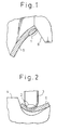
- the thickness of the edge portion is increased as shown by numeral 1 in rig. 1. This increase of thickness 1 is a factor to impair the size accuracy.
- edge forming rolls disclosed in Japanese Unexamined Patent Publication (Kokai) No. 62-166027 can be applied to a wide range of pipe diameters; however, since the radius of curvature of the roll is continuously changed, the roll locally comes into contact with the metallic strip, so that the problem of defective profile tends to occur, and this method is not appropriate for forming thick wall pipes.
- JP-A-49-35500 on which the preambles of claims 1 and 8 are based, discloses the bending of the edges of metallic strip between upper and lower forming rolls; the rolls can be skewed relative to the machine direction about a vertical axis, to maintain central positioning of the metallic strip, but each upper roll remains aligned with its co-operating lower roll.
- JP-A-4-182024 discloses the use of upper and lower pairs of rolls for bending metallic strip edges, the rolls being designed to operate with a variety of stip sizes to give a variety of strip edge curvatures, but the upper rolls are not skewed relative to the lower.
- the present invention provides a method of bending the longitudinal edges of a metallic strip for welded pipe formation by passing the strip longitudinally in contact with a laterally spaced pair of first rotating rolls each cooperating with a second rotating roll to engage and bend a respective strip edge, the rotational axes of said first and second rolls being in respective first and second spaced parallel planes, characterised in that each first roll is skewed relative to the co-operating second roll about an axis perpendicular to said spaced parallel planes.
- the first rotating rolls are preferably skewed so that they converge in the machine direction towards the longitudinal centerline of the metallic strip.
- Each first rotating roll may co-operate with a second rotating roll whose rotational axis is perpendicular to the longitudinal centerline of the metallic strip, i.e. which is aligned in the machine direction.
- Thr first rotating rolls are preferably skewed so that there is an angle ⁇ ⁇ ⁇ 45° between its rotational axis and the line parallel to said spaced parallel planes and perpendicular to the longitudinal centerline (7) of the metallic strip (5).
- each first rotating roll co-operates with a respective second rotating roll which is skewed relative to the longitudinal centerline of the metallic strip about an axis perpendicular to said spaced parallel planes in a direction opposite to the skewing of the respective first rotating roll.
- each second rotating roll is preferably skewed to give an angle ⁇ d ⁇ 30° between its rotational axis and the line parallel to said spaced parallel planes and perpendicular to the longitudinal centerline of the metallic strip.
- the two first rotating rolls are preferably displaced relative to one another in the machine direction.
- the invention also provides a forming stand for bending the longitudinal edges of a metallic strip for welded pipe formation, the stand comprising a laterally spaced pair of first rotating rolls each co-operating with a second rotating roll for engaging and bending a respective edge of a metallic strip passed therethrough in the machine direction, the rotational axes of said first and second rotating rolls being in respective first and second spaced parallel planes, characterised by means for adjusting the lateral spacing between the first rotating rolls and by means for selectively skewing each first rotating roll relative to the co-operating second roll about an axis perpendicular to said spaced parallel planes.
- each first rotating roll co-operates with a respective second rotating roll
- the stand including means for adjusting the lateral spacing of the second rotating rolls and means for skewing each second rotating roll relative to the machine direction about an axis perpendicular to said spaced parallel planes.
- metallic strips can be accurately formed into pipes with thin or thick walls with two pairs of upper and lower horizontal edge forming rolls disposed on both sides of the metallic strip in a breakdown stand, wherein the edge forming is performed with the upper and lower horizontal rolls crossed or skewed relative to each other about a vertical axis.
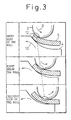
- a pair of upper and lower horizontal edge forming rolls 3, 4 are crossed, and the upper and lower rolls are continuously contacted with both sides of a metallic strip 5 to be formed right below the upper forming roll. Therefore, in this forming process, localized contact of the forming roll and the metallic strip can be avoided, which is different from the forming process of the prior art.
- Fig. 4(a) shows a case of a small wall thickness
- Fig. 4(b) shows a case of low curvature (large pipe diameter)
- Fig. 4(c) shows a case of large wall thickness.
- Fig. 4(d) in which a case of high curvature (small pipe diameter) is shown, when the orientation of the lower roll is changed, the radius of curvature formed by the lower roll coming into contact with the outside of the metallic strip is changed, and when two pairs of upper and lower rolls disposed on both sides are moved so as to be adjusted in the width direction of the metallic strip in accordance with the strip width, the edge forming rolls can be shared by metallic strips of different sizes from which pipes of different sizes are formed.
- the orientation of the upper roll is determined by the profile of the upper roll caliber, the outside diameter of the pipe to be formed from the metallic strip, the wall thickness of the metallic strip, and the upper roll diameter.
- the orientation of the lower roll is determined by the profile of the lower roll caliber, the outside diameter of the pipe to be formed from the metallic strip, and the lower roll diameter.
- the orientations of the upper and lower rolls are limited as follows.
- the upper limit of the turning angle is determined to be 45°.
- the range of metallic strips to be formed is extended.
- the upper limit of the turning angle is determined to be 30°. Due to the foregoing, the range of the diameter of the pipe to be formed from the metallic strip can be extended by 1.5 to 2.0 times.
- each pair of upper and lower rolls maybe disposed at different positions with respect to the metallic strip forming direction. Therefore, after the forming of one edge of the metallic strip has been started, the forming of the other edge is started. Due to the foregoing, in the case where small size pipes are formed, interference of the forming rolls on both sides caused when the upper and lower rolls are skewed can be avoided, so that the turning angles of the forming rolls are not restricted. In this case, an interval with respect to the metallic strip forming direction between the pairs of upper and lower rolls disposed on both sides, is determined by the diameters of the upper and lower rolls and the range of the designed turning angle.
- the horizontal upper rolls divided with respect to the metallic strip width direction are disposed on both sides for the purpose of edge forming.
- the horizontal upper rolls are selectively skewed about a vertical axis.
- the turning angle of the upper roll is determined by the profile of the upper roll caliber, the outside diameter of the pipe to be formed from the metallic strip, the wall thickness of the metallic strip, and the upper roll diameter.
- the turning angle direction of the upper roll is limited as follows.
- the upper limit of the turning angle is determined to be 45°.
- the roll direction will be explained as follows.
- the upper and lower rolls are divided into two, slippage is caused between the rolls and the metallic strip when the upper and lower rolls are skewed. Therefore, a force is applied to the rolls in the width direction of the metallic strip, and torsion is generated in the rolls.
- the upper rolls converge in the machine direction, i.e. they are directed to the edges of the metallic strip on the entry side of the roll stand and to the center of the metallic strip on the delivery side of the roll stand.
- the lower rolls are positioned in the opposite direction to that of the upper rolls. In the manner described above, the upper and lower rolls are crossed with each other.
- the above roll arrangement will be referred to hereinafter as "a converging forming roll arrangement".
- the upper roll is given a thrust directed inwards
- the lower roll is given a thrust directed outwards.
- a deviation directed outwards in the width direction is caused in the upper roll
- a deviation directed inwards in the width direction is caused in the lower roll.
- the upper rolls diverge in the machine direction, i.e. they are directed to the center of the metallic strip on the entry side of the roll stand and to the edge of the metallic strip on the delivery side of the roll stand.
- the lower rolls are positioned in the opposite direction to that of the upper roll.
- the upper and lower rolls are crossed with each other.
- the above roll arrangement will be referred to hereafter as "a diverging forming roll arrangement".
- a deviation directed inwards in the width direction is caused in the upper roll, and a deviation directed outwards in the width direction is caused in the lower roll.
- the diverging forming roll arrangement the following problems are caused:
- the converging forming roll arrangement in the case of "the converging forming roll arrangement", the above problems are not caused, and further the torsion forces applied to the upper and lower rolls are advantageous for edge forming, and the reduction force of the upper and lower roils is advantageously reduced. Accordingly, in the case of a roll stand in which torsion tends to occur due to insufficient rigidity, it is preferable to employ "the converging forming roll arrangement".
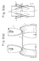
- Fig. 8(a) is a front view of rolls to which the present invention is applied
- Fig. 8(b) is a plan view.
- the turning angle ⁇ d of the lower roll 4 is determined in accordance with the forming radius of curvature of the edge portion 13 of the metallic strip 5.
- the positions of upper and lower rolls on both sides are determined with respect to the width direction.
- the turning angle ⁇ u of the upper roll 3 is determined.
- Fig. 9 is a front view of an example of an edge bending roll stand to which the present invention is applied.
- the roll support beam members 14, 15 vertically hold the upper and lower roll bearing members 17, 18, and the upper roll support beam member 14 is vertically moved and fixed by the action of the reduction screw shaft 16.
- the upper and lower roll support stands 19, 20 are moved and fixed in the width direction by the rotation of a screw shaft not shown in the drawing or by the sliding motion of a sliding bracket on a rail not shown in the drawing, wherein the screw shaft or the sliding bracket is disposed in the beam members 14, 15. Further, the upper and lower roll support stands 19, 20 are adjustably skewed on a vertical shaft by means of a gear drive unit not shown in the drawing.
- bearing members for supporting the middle portions of the upper and lower rolls, or a bearing member for supporting one of them may be fixed to the roll support beam members 14, 15.
- two pairs of upper and lower horizontal rolls are disposed on both sides of the same stands.
- two pairs of upper and lower rolls are disposed at different positions, and after one pair of rolls have completed edge forming of the edge on one side, the other pair of roll start edge forming of the edge on the other side.
- the two pairs of forming rolls may be disposed in different roll stands. Further, it is possible to provide a guide roll at the side where edge forming is not conducted.
- Figs. 10a and 10b show the distributions of radius of curvature and wall thickness after a steel strip of ⁇ 50.8 ⁇ t2.10 mm, the yield strength of which was 294 N/mm 2 , was subjected to edge forming, wherein one is a case to which the present invention was applied and the other is a conventional case to which the present invention was not applied.
- edge forming the converging forming roll arrangement
- steel strips of small wall thickness were not sufficiently bent, and indentations were caused on steel strips of large wall thickness.
- excellent profiles were provided.
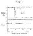
- Fig. 11 shows the distributions of radius of curvature and wall thickness after a steel strip of ⁇ 34.0 ⁇ t5 mm was subjected to edge forming, wherein the same forming rolls as those described above were used and the turning angle was adjusted.
- the obtained radius of curvature was approximately the same as the radius of curvature which was previously set, and further the provided profile was good. It can be seen that the outer diameter of the forming roll can be shared when the present invention is applied.
- Table 1 shows the results on the radius of curvature and the reduced wall thickness in the case where edge forming was conducted using the same rolls, wherein the turning angles of the upper and lower rolls were changed with respect to various forming diameter and wall thickness. It can be seen that the edge forming properties were improved, the reduction of wall thickness was decreased, and the roll outer diameter was shared, when the present invention was applied. Further, when the turning angle limits described above for the present invention were observed, the effects of the present invention were exhibited to the maximum. No.
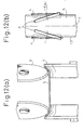
- Fig. 12(a) is a front view
- Fig. 12(b) is a plan view, of rolls to which the present invention is applied.
- the dimensions of the lower roll 4 are determined in accordance with the width of the metallic strip 5 and the size of the portion of the metallic strip 5 to be bent, and the positions of upper and lower role on both sides with respect to the width direction are also determined in accordance with the width of the metallic strip 5 and the size of the portion of the metallic strip 5 to be bent. Further, in accordance with the wall thickness of the metallic strip 5, the turning angle ⁇ ⁇ of the upper roll 3 is determined, and numeral 7 is the centerline of the metallic strip.
- the hysteresis of the upper roll gap right below the upper roll 3 is shown in Fig. 4, and the hysteresis of the lower roll is the same as that of the conventional case.
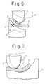
- Circumstances of the metallic strip deformed in accordance with the roll gap hysteresis are shown in Fig. 3, in which numeral 3 is an upper roll, numeral 4 is a lower roll, and numeral 5 is a metallic strip.
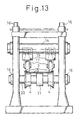
- Fig. 13 is a front view of an exemplary edge bend roll stand to which the present invention is applied.
- the roll support beam member 14 vertically holds the upper roll bearing member 17, and the upper roll support beam member 14 is vertically moved and fixed by the action of the reduction screw shaft 16.
- the upper roll support stand 19 is moved and fixed in the width direction by the rotation of a screw shaft not shown in the drawing or by the sliding motion of a sliding bracket on a rail not shown in the drawing, wherein the screw shaft or the sliding bracket is disposed in the beam member 14. Further, the upper roll support stand 19 is skewed and fixed on a vertical shaft by means of a gear drive unit not shown in the drawing.
- the lower rolls 4 can be rotated by the lower roll shaft 20 through the lower roll bearing members 18. The positions of the lower rolls 4 can be changed and fixed in the width direction by means of a screw means or hydraulic means not shown in the drawing.
- a bearing member for supporting the middle portion of the upper roll may be fixed to the roll support beam member 14.
- Table 2 shows the results of radius of curvature and reduced wall thickness in the case where edge forming was conducted using the same rolls, wherein the turning angles of the upper roll was changed with respect to various wall thickness. It can be seen that the edge forming properties were improved and the reduction of wall thickness was decreased when the present invention was applied. Further, when the turning angle limits described above for the the present invention were observed, the effects of the present invention were exhibited at the maximum. No.
- the metallic strip when a metallic strip is continuously formed by rolls and then welded so as to manufacture a welded pipe, the metallic strip is subjected to edge forming by the breakdown roll unit provided in the initial edge forming process without impairing the accuracy of the wall thickness of the metallic strip to be formed. Further, the forming roll can be shared when metallic strips for various pipe diameters are formed.
Landscapes
- Engineering & Computer Science (AREA)
- Mechanical Engineering (AREA)
- Bending Of Plates, Rods, And Pipes (AREA)
Claims (10)
- Procédé de pliage des bords longitudinaux (13) d'une bande métallique (5) pour la formation de tubes soudés en faisant passer la bande (5) longitudinalement en contact avec une paire latéralement espacée de premiers rouleaux en rotation (3) qui coopèrent chacun avec un deuxième rouleau en rotation (4) afin d'engager et plier un bord de bande respectif (13), les axes de rotation desdits premier et deuxième rouleaux (3, 4) étant dans des premier et deuxième plans parallèles espacés respectifs, caractérisé en ce que chaque premier rouleau (3) est décalé par rapport au deuxième rouleau qui coopère (4) autour d'un axe perpendiculaire aux dits plans parallèles espacés.
- Procédé selon la revendication 1, dans lequel les premiers rouleaux en rotation (3) sont de préférence décalés de telle sorte qu'ils convergent dans la direction de la machine vers l'axe longitudinal (7) de la bande métallique (5).
- Procédé selon la revendication 1 ou 2, dans lequel chaque premier rouleau en rotation (3) est décalé de telle sorte qu'il y a un angle αµ ≤ 45° entre son axe de rotation et la ligne parallèle aux dits plans parallèles espacés et perpendiculaire à l'axe longitudinal (7) de la bande métallique (5).
- Procédé selon l'une quelconque des revendications précédentes dans lequel chaque premier rouleau en rotation (3) coopère avec un deuxième rouleau en rotation (4) dont l'axe de rotation est perpendiculaire à l'axe longitudinal (7) de la bande métallique (5).
- Procédé selon l'une quelconque des revendications 1 à 3, dans lequel chaque premier rouleau en rotation (3) coopère avec un deuxième rouleau en rotation respectif (4) qui est décalé par rapport à l'axe longitudinal (7) de la bande métallique (5) autour d'un axe perpendiculaire aux dits plans parallèles espacés dans une direction opposée au décalage du premier rouleau en rotation respectif (3).
- Procédé selon la revendication 5, dans lequel chaque deuxième rouleau en rotation (4) est décalé afin de donner un angle αd ≤ 30° entre son axe de rotation et la ligne parallèle auxdits plans parallèles espacés et perpendiculaire à l'axe longitudinal (7) de la bande métallique (5).
- Procédé selon l'une quelconque des revendications précédentes, dans lequel un des premiers rouleaux en rotation (3) est de préférence déplacé par rapport à l'autre dans la direction de la machine.
- Cage de formage destinée à plier les bords longitudinaux d'une bande métallique (5) pour la formation de tubes soudés, la cage comportant une paire latéralement espacée de premiers rouleaux en rotation (3) qui coopèrent chacun avec un deuxième rouleau en rotation (4) afin d'engager et plier un bord respectif (3) d'une bande métallique (5) qui passe à travers dans la direction de la machine, les axes de rotation desdits premiers et deuxièmes rouleaux en rotation étant dans des premier et deuxième plans parallèles espacés respectifs, caractérisée par des moyens destinés à ajuster l'espacement latéral entre les premiers rouleaux en rotation (3) et par des moyens destinés à décaler de manière sélective chaque premier rouleau en rotation (3) par rapport au deuxième rouleau qui coopère (4) autour d'un axe perpendiculaire aux dits plans parallèles espacés.
- Cage de formage selon la revendication 8, dans laquelle chaque premier rouleau en rotation (3) coopère avec un deuxième rouleau en rotation respectif (4), la cage comprenant des moyens destinés à ajuster l'espacement latéral des deuxièmes rouleaux en rotation (4) et des moyens destinés à décaler chaque deuxième rouleau en rotation (4) par rapport à la direction de la machine autour d'un axe perpendiculaire aux dits plans parallèles espacés.
- Cage de formage selon la revendication 8 ou 9, dans laquelle un des premiers rouleaux (3) est déplacé par rapport à l'autre dans la direction de la machine.
Applications Claiming Priority (13)
| Application Number | Priority Date | Filing Date | Title |
|---|---|---|---|
| JP25670892 | 1992-09-25 | ||
| JP25670892 | 1992-09-25 | ||
| JP256708/92 | 1992-09-25 | ||
| JP5014283A JPH05317979A (ja) | 1992-03-25 | 1993-01-29 | 溶接管の成形方法および成形スタンド |
| JP14282/93 | 1993-01-29 | ||
| JP1428493A JP2642575B2 (ja) | 1992-09-25 | 1993-01-29 | 溶接管の成形方法および成形スタンド |
| JP1428293A JPH05309422A (ja) | 1992-03-13 | 1993-01-29 | 溶接管の成形方法および成形スタンド |
| JP1428493 | 1993-01-29 | ||
| JP14284/93 | 1993-01-29 | ||
| JP14283/93 | 1993-01-29 | ||
| JP1428393 | 1993-01-29 | ||
| JP1428293 | 1993-01-29 | ||
| PCT/JP1993/001265 WO1994007621A1 (fr) | 1992-09-25 | 1993-09-07 | Procede de formage de tubes soudes et support de formage prevu a cet effet |
Publications (3)
| Publication Number | Publication Date |
|---|---|
| EP0623403A1 EP0623403A1 (fr) | 1994-11-09 |
| EP0623403A4 EP0623403A4 (fr) | 1995-11-29 |
| EP0623403B1 true EP0623403B1 (fr) | 1999-11-17 |
Family
ID=27456166
Family Applications (1)
| Application Number | Title | Priority Date | Filing Date |
|---|---|---|---|
| EP93919622A Expired - Lifetime EP0623403B1 (fr) | 1992-09-25 | 1993-09-07 | Procede de formage de tubes soudes et support de formage prevu a cet effet |
Country Status (3)
| Country | Link |
|---|---|
| EP (1) | EP0623403B1 (fr) |
| DE (1) | DE69327045T2 (fr) |
| WO (1) | WO1994007621A1 (fr) |
Families Citing this family (1)
| Publication number | Priority date | Publication date | Assignee | Title |
|---|---|---|---|---|
| CN104889208A (zh) * | 2015-05-28 | 2015-09-09 | 南京皓威机械有限公司 | 多自由度三辊制管机 |
Family Cites Families (3)
| Publication number | Priority date | Publication date | Assignee | Title |
|---|---|---|---|---|
| JPS4935500B1 (fr) * | 1970-12-05 | 1974-09-24 | ||
| JP2692176B2 (ja) * | 1988-10-07 | 1997-12-17 | 住友金属工業株式会社 | 溶接管の製造装置 |
| JPH0698402B2 (ja) * | 1990-11-14 | 1994-12-07 | 川崎製鉄株式会社 | 溶接鋼管の帯板縁部成形ロール |
-
1993
- 1993-09-07 DE DE69327045T patent/DE69327045T2/de not_active Expired - Fee Related
- 1993-09-07 EP EP93919622A patent/EP0623403B1/fr not_active Expired - Lifetime
- 1993-09-07 WO PCT/JP1993/001265 patent/WO1994007621A1/fr not_active Ceased
Also Published As
| Publication number | Publication date |
|---|---|
| WO1994007621A1 (fr) | 1994-04-14 |
| EP0623403A1 (fr) | 1994-11-09 |
| DE69327045D1 (de) | 1999-12-23 |
| DE69327045T2 (de) | 2000-06-29 |
| EP0623403A4 (fr) | 1995-11-29 |
Similar Documents
| Publication | Publication Date | Title |
|---|---|---|
| RU2402396C2 (ru) | Способ непрерывного формирования изогнутого и/или скрученного профилей и производственная линия | |
| US20020062672A1 (en) | Pipe formed by bending rolls | |
| US4122696A (en) | Method and apparatus for manufacturing metallic pipe | |
| US6318141B1 (en) | Roller leveller | |
| US4385512A (en) | Tandem rolling mill train for metal plate and sheet | |
| JPWO2000003817A1 (ja) | ローラレベラ | |
| EP1135223A4 (fr) | Procede et installation de profilage-etirage | |
| EP0484854B1 (fr) | Procédé pour le laminage de poutrelles en H | |
| US5016459A (en) | Method and guide roll stand for guiding and shaping strip material in a pipe mill | |
| JP2550268B2 (ja) | 溶接管の成形方法および成形スタンド | |
| EP0623403A1 (fr) | Procede de formage de tubes soudes et support de formage prevu a cet effet | |
| US4685320A (en) | Method of rolling steel rods and wires with grooveless rolls and grooveless rolling entry guide | |
| US5704243A (en) | Forming method and forming stand for welded pipes | |
| CN109772951B (zh) | 具有公用辊的金属焊管成型装置及其生产方法 | |
| SU1816669A1 (en) | Knurling roller | |
| US5878614A (en) | Finn pass forming device for forming seam welded steel pipes and roller device available for forming seam welded steel pipes of a plurality of sizes | |
| US3270543A (en) | Machine for flattening and curling of metal strip | |
| CN113305147B (zh) | 一种铜棒材轧制宽铜板的多工序加工装置及其方法 | |
| JPH0312977B2 (fr) | ||
| JPS6277107A (ja) | 偏心リング型エツジング圧延装置 | |
| JP3332217B2 (ja) | ベンディングロールによるパイプ成形方法 | |
| CN120306496B (zh) | 一种散热器边板冷弯成型自动化装备 | |
| JP2642575B2 (ja) | 溶接管の成形方法および成形スタンド | |
| JP2661470B2 (ja) | 細径線材の製造装置 | |
| JP2004141925A (ja) | 形鋼の曲げ加工方法およびその装置 |
Legal Events
| Date | Code | Title | Description |
|---|---|---|---|
| PUAI | Public reference made under article 153(3) epc to a published international application that has entered the european phase |
Free format text: ORIGINAL CODE: 0009012 |
|
| 17P | Request for examination filed |
Effective date: 19940526 |
|
| AK | Designated contracting states |
Kind code of ref document: A1 Designated state(s): DE FR GB |
|
| A4 | Supplementary search report drawn up and despatched |
Effective date: 19951013 |
|
| AK | Designated contracting states |
Kind code of ref document: A4 Designated state(s): DE FR GB |
|
| 17Q | First examination report despatched |
Effective date: 19970423 |
|
| GRAG | Despatch of communication of intention to grant |
Free format text: ORIGINAL CODE: EPIDOS AGRA |
|
| GRAG | Despatch of communication of intention to grant |
Free format text: ORIGINAL CODE: EPIDOS AGRA |
|
| GRAG | Despatch of communication of intention to grant |
Free format text: ORIGINAL CODE: EPIDOS AGRA |
|
| GRAH | Despatch of communication of intention to grant a patent |
Free format text: ORIGINAL CODE: EPIDOS IGRA |
|
| GRAH | Despatch of communication of intention to grant a patent |
Free format text: ORIGINAL CODE: EPIDOS IGRA |
|
| GRAA | (expected) grant |
Free format text: ORIGINAL CODE: 0009210 |
|
| AK | Designated contracting states |
Kind code of ref document: B1 Designated state(s): DE FR GB |
|
| REF | Corresponds to: |
Ref document number: 69327045 Country of ref document: DE Date of ref document: 19991223 |
|
| ET | Fr: translation filed | ||
| PLBE | No opposition filed within time limit |
Free format text: ORIGINAL CODE: 0009261 |
|
| STAA | Information on the status of an ep patent application or granted ep patent |
Free format text: STATUS: NO OPPOSITION FILED WITHIN TIME LIMIT |
|
| 26N | No opposition filed | ||
| REG | Reference to a national code |
Ref country code: GB Ref legal event code: IF02 |
|
| PGFP | Annual fee paid to national office [announced via postgrant information from national office to epo] |
Ref country code: GB Payment date: 20020904 Year of fee payment: 10 |
|
| PGFP | Annual fee paid to national office [announced via postgrant information from national office to epo] |
Ref country code: FR Payment date: 20020910 Year of fee payment: 10 |
|
| PGFP | Annual fee paid to national office [announced via postgrant information from national office to epo] |
Ref country code: DE Payment date: 20020911 Year of fee payment: 10 |
|
| PG25 | Lapsed in a contracting state [announced via postgrant information from national office to epo] |
Ref country code: GB Free format text: LAPSE BECAUSE OF NON-PAYMENT OF DUE FEES Effective date: 20030907 |
|
| PG25 | Lapsed in a contracting state [announced via postgrant information from national office to epo] |
Ref country code: DE Free format text: LAPSE BECAUSE OF NON-PAYMENT OF DUE FEES Effective date: 20040401 |
|
| GBPC | Gb: european patent ceased through non-payment of renewal fee |
Effective date: 20030907 |
|
| PG25 | Lapsed in a contracting state [announced via postgrant information from national office to epo] |
Ref country code: FR Free format text: LAPSE BECAUSE OF NON-PAYMENT OF DUE FEES Effective date: 20040528 |
|
| REG | Reference to a national code |
Ref country code: FR Ref legal event code: ST |