EP0484854B1 - Procédé pour le laminage de poutrelles en H - Google Patents
Procédé pour le laminage de poutrelles en H Download PDFInfo
- Publication number
- EP0484854B1 EP0484854B1 EP91118768A EP91118768A EP0484854B1 EP 0484854 B1 EP0484854 B1 EP 0484854B1 EP 91118768 A EP91118768 A EP 91118768A EP 91118768 A EP91118768 A EP 91118768A EP 0484854 B1 EP0484854 B1 EP 0484854B1
- Authority
- EP
- European Patent Office
- Prior art keywords
- rolling
- web
- rolls
- billet
- flanges
- Prior art date
- Legal status (The legal status is an assumption and is not a legal conclusion. Google has not performed a legal analysis and makes no representation as to the accuracy of the status listed.)
- Expired - Lifetime
Links
- 238000005096 rolling process Methods 0.000 title claims description 142
- 238000000034 method Methods 0.000 title claims description 54
- 229910000831 Steel Inorganic materials 0.000 claims description 15
- 239000010959 steel Substances 0.000 claims description 15
- 238000011144 upstream manufacturing Methods 0.000 claims description 7
- 230000009467 reduction Effects 0.000 description 60
- 230000007547 defect Effects 0.000 description 8
- 230000015556 catabolic process Effects 0.000 description 7
- 230000006835 compression Effects 0.000 description 3
- 238000007906 compression Methods 0.000 description 3
- 238000010276 construction Methods 0.000 description 3
- 230000000694 effects Effects 0.000 description 3
- 238000002474 experimental method Methods 0.000 description 3
- 238000009434 installation Methods 0.000 description 3
- 238000011835 investigation Methods 0.000 description 3
- 238000004519 manufacturing process Methods 0.000 description 3
- 239000000463 material Substances 0.000 description 2
- 230000001154 acute effect Effects 0.000 description 1
- 230000006866 deterioration Effects 0.000 description 1
- 230000001627 detrimental effect Effects 0.000 description 1
- 238000007730 finishing process Methods 0.000 description 1
- 238000005098 hot rolling Methods 0.000 description 1
- 238000005304 joining Methods 0.000 description 1
- 230000002035 prolonged effect Effects 0.000 description 1
- 230000000452 restraining effect Effects 0.000 description 1
- 238000003466 welding Methods 0.000 description 1
Images


Classifications
-
- B—PERFORMING OPERATIONS; TRANSPORTING
- B21—MECHANICAL METAL-WORKING WITHOUT ESSENTIALLY REMOVING MATERIAL; PUNCHING METAL
- B21B—ROLLING OF METAL
- B21B1/00—Metal-rolling methods or mills for making semi-finished products of solid or profiled cross-section; Sequence of operations in milling trains; Layout of rolling-mill plant, e.g. grouping of stands; Succession of passes or of sectional pass alternations
- B21B1/08—Metal-rolling methods or mills for making semi-finished products of solid or profiled cross-section; Sequence of operations in milling trains; Layout of rolling-mill plant, e.g. grouping of stands; Succession of passes or of sectional pass alternations for rolling structural sections, i.e. work of special cross-section, e.g. angle steel
- B21B1/088—H- or I-sections
Definitions
- This invention relates to a method of rolling H-beams or wide flange beams by universal mills according to the precharacterising part of claims 1 and 3 respectively, which is advantageously used in case of continuously producing H-beams with keeping a constant web width in spite of wear of rolls used in rolling, or producing various H-beams different in size with the same rolling installation.
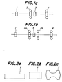
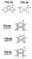
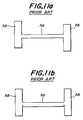
- H-beams are produced by hot rolling steel blanks 5, 6 or 7 having various cross-sections as shown in Figs. 2a to 2c in a line including a breakdown mill 1, a universal roughing mill 2, an edger mill 3 and a universal finishing mill 4 which are arranged progressively downstream of the flowing of the steel blanks as shown in Figs. 1a and 1b.
- the blanks (slab 5, rectangular billet 6 and H-beam billet 7) shown in Figs. 2a to 2c are first roughly rolled to predetermined shapes in the breakdown mill 1.
- the breakdown mill 1 used in this case is usually composed of a pair of upper and lower caliber rolls having open passes 8 or closed passes 9 as shown in Figs. 3a and 3c.
- the steel blanks are rolled successively through a plurality of passes of the caliber rolls in plural passes to be rolled into shapes suitable for later intermediate rolling processes.
- the steel blanks thus rolled are intermediately rolled in at least one universal roughing mill 10 having rolls of shapes shown in Fig. 4a and at least one edger mill 11 having rolls of shapes shown in Fig. 4b in one pass or plural passes.
- the steel blanks are then rolled in a universal finishing mill 12 having rolls of shapes shown in Fig. 4c usually in one pass to H-beam steel products. Therefore, sizes of rolls of the finishing universal mill 12 and the rolling mills upstream thereof are determined depending upon the size of the products.
- the rolls are so designed that distance (a) in Fig. 3a and distances (b), (c) and (d) in Figs. 4a, 4b and 4c are substantially equal to each other.
- the H-beams rolled by such horizontal rolls having the particular widths have substantially constant inner web widths.
- roll gaps between the horizontal rolls and between vertical rolls must be changed in order to roll one series of section steels of several kinds having different thicknesses by the use of the same rolls without exchanging them.
- the difference between the maximum and minimum thicknesses of flanges of the rolled H-beams becomes, for example, as much as approximately 16 mm.
- the outer web width is an inner web width plus thicknesses of two flanges, the outer web width varies within 32 mm which is twice 16 mm.
- H-beams including those of various outer web widths in the rolling methods of the prior art described above. If such H-beams are used as building or construction beams, there are the following problems.
- H-beams made of steel plates by welding have been used particularly for buildings, which are welded to form H-beams having constant outer web widths, even if thicknesses of their flanges are not uniform.
- welded H-beams are disadvantageous because of high manufacturing cost.
- defects of H-beams are often caused such as overlapping at rounded portions, buckling of webs or shifting of webs from center positions, when rolling reduction of the inner web widths is relatively large.
- H-beams having constant outer web widths can be effectively produced, even if rolling is applied to billets to modify thicknesses of their flanges. Even in this method, however, the reduction of the outer web widths is limited as explained hereinafter. Therefore, a rolling system has been expected which is able to realize larger reduction of web widths.
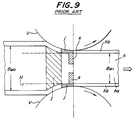
- the inner web width Bw 0 is reduced by the vertical rolls V, they contact the billet h prior to contacting of the horizontal rolls H with a normal rolling reduction and normal roll diameters so that the web width of the billet h is reduced until end surfaces of the horizontal rolls H contact the billet h.
- the reduction of the inner web width Bw 0 is effected mainly at zones located slightly upstream of zones k where the horizontal rolls contact the web ha of the billet h.
- roll gaps between the upper and lower horizontal rolls H are more than the thickness of the web ha as shown in Fig. 10a.
- buckling or torsion of the web ha may occur as the case may be as shown in Figs. 10b and 10c.
- the billet h rolled by finish rolling will be shaped substantially determined by the roll gaps between the upper and lower horizontal rolls H even if buckling occurs before the reduction by the horizontal rolls H.
- contacting pressure between the web ha and the horizontal rolls H becomes locally higher to cause defects such as flaws or cracks in surfaces of the web ha.
- the torsion of the web ha as shown in Fig. 10a or 10c permits the billet to pass through the finishing mill in a condition of longitudinal center lines of the flanges hb shifted from the roll gaps between the horizontal rolls H. Consequently, the web ha of finished product is often shifted relative to the flanges hb in opposite directions or one direction as shown in Fig. 11a or 11b.
- the thicknesses of webs of billets before finish rolling are determined by appropriate rolling reduction in universal rolling.
- the inner web widths of billets before finish rolling are substantially equal to inner web widths of billets having the thinnest flange thicknesses in one rolling operation. Therefore, in order to prevent the defects in finish rolling described above, it is necessary to provide a limitation of rolling reduction in one pass according to thicknesses and inner widths of webs. If a required rolling reduction exceeds this limitation, the rolling is required to be divided into two or more passes.
- the method previously proposed (the Japanese Patent Application Laid-open No. 2-80,102) by the inventors of the present invention is fundamentally different from the other methods (Japanese Patent Application Laid-open Nos. 2-84,203, 2-147,102 and 2-117,112) in the feature of rolling to reduce web widths and substantially at the same time to reduce flange thicknesses.
- Japanese Patent Application Laid-open Nos. 2-84,203, 2-147,102 and 2-117,112 Japanese Patent Application Laid-open Nos. 2-84,203, 2-147,102 and 2-117,112
- ⁇ Bwmax the limit value of rolling reduction of inner web width
- Tw 2 (mm) is web thickness before being rolled
- Bw (mm) is inner web width.
- the method of producing an H-beam by finish rolling comprises the features of claim 1.
- the billet is rolled by the universal finishing mill whose pair of vertical rolls are positively driven.
- limit values of the rolling reduction can be considerably enlarged so that lifetime of the rolls is prolonged and exchange of rolls becomes minimum, thereby more improving production efficiency of H-beams by rolling.
- a universal mill is usually constructed so that four center axes of a pair of horizontal rolls and a pair of vertical rolls are located in a plane perpendicular to the rolling direction.
- the inventors have performed various experiments and investigation on arrangement of the rolls of rolling mills in rolling accompanied with reduction of web widths of H-beams. As a result, they ultimately found that shifting the vertical or horizontal rolls incorporated in a rolling mill in the rolling direction relative to the horizontal or vertical rolls is very effective in order to enlarge the permissible limitation of rolling reduction of inner web widths.
- the present invention resides in the above discovery.
- a steel billet rolled in rough rolling and having a web and flanges is finish rolled by a universal rolling mill to reduce the web width and thicknesses of the flanges of the billet and to correct inclination of the flanges, whereby the inner web width of the billet is reduced or adjusted.
- the universal mill includes a pair of vertical rolls embracing the flanges of the billet on both sides and a pair of horizontal rolls having widths less than those in the rough rolling and embracing the web on upper and lower sides. According to the method of invention, the rolling is effected in the state that the vertical rolls are shifted onto the downstream side of the horizontal rolls into an area including a zone where the reduction of the web width and the thicknesses of the flanges are simultaneously effected.
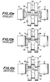
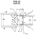
- Figs. 12 and 13 schematically illustrate contact states between rolls and rough rolled steel billets and reaction forces of vertical rolls acting upon web surfaces in the event that the reduction or adjustment of inner web widths is performed by a universal finishing mill having horizontal rolls of widths less than the inner web widths of the rough rolled steel billet.
- Fig. 12 illustrates the case that the vertical rolls V are shifted onto the downstream side according to the invention, while Fig. 13 shows the vertical and horizontal rolls whose axes are all in a plane according to the prior art methods.
- the width of the horizontal rolls is Bw 1 which is less than the inner web width Bw 0 of the rough rolled billet h rolled by roughing rolling as shown in Fig. 13 illustrating the prior art
- the following is the contact state between the flanges hb and the web ha of the billet h and the vertical rolls V and horizontal rolls (not shown).
- the rough rolled billet h entered into the rolling mill from its entrance contacts the vertical rolls V with its outer surfaces of the flanges hb.
- the inner surfaces of the flanges hb do not contact the end faces of the horizontal rolls H yet, with the result that the rolling is effected only to reduce the web width by vertical rolls V (zone I).
- the inner surfaces of the flanges hb contact the end faces of the horizontal rolls H.
- the reduction of the web width is no longer effected, but the reduction of thicknesses of the flanges hb is performed.
- the barrel surfaces of the horizontal rolls do not contact the surfaces of the web ha under the normal rolling condition with the normal roll diameter (zone J).
- the barrel surfaces of the horizontal rolls contact the web ha to reduce its thickness and at the same time the reduction of the thicknesses of the flanges hb progresses (zone K).
- the reduction of web width is effected in the zone I on the entrance side of the rolling mill in this manner.
- the zone I is near the zone K where the web is comparatively securely restrained by the vertical rolls H, so that the possibility of the buckling of the web determined only by the reaction forces P is not so high.
- the web ha is subjected to the reaction forces Pf from the vertical rolls V in the rolling direction because only the horizontal rolls are positively driven but vertical rolls are not positively driven in the usual universal mill and only driven by frictional force with the billet advancing in the downstream direction.
- the rough rolled billet h is subjected to a driving power with its web ha in the zone K where the web ha is rolled to reduce its thickness and with the flanges hb in zones J and K where the flanges hb contacting the horizontal rolls are rolled to reduce their thicknesses.
- the zone I on the other hand, although the outer surfaces of the flanges hb contact the vertical rolls V, the rough rolled billet h is not subjected to any driving power because the vertical rolls do not have any driving force. Consequently, the billet in the zone I is pulled by the part of the billet downstream of the zone I. However, the reduction of web width is being performed in the zone I so that resistance occurs against the pulling force in the rolling direction. Therefore, reaction forces Pf in the rolling direction is applied to the billet from the vertical rolls V as a reaction against the pulling force.
- the web hb in the zone I is subjected to the reaction forces P from the vertical rolls V, which are resultant forces of the reaction forces Pw in the directions of the web width and the reaction forces Pf in the rolling direction.
- the reaction forces P are higher than the reaction forces Pw and tend to buckle the web upstream of the zone I. Consequently, great compressive forces act upon the web in an area where the web is hardly restrained and remote from the zone K where the web is restrained, with the result that the limit value of the rolling reduction of web width becomes low.
- the vertical rolls V are shifted onto the downstream side of the rolling mill so that the zone I where the reduction of the web width is performed is made to overlap the zone K where the web of the billet is restrained by the horizontal rolls, while the part of web upstream of the zone I and subjected to the reaction forces P is brought into the position as near as possible to the zone K where the web is restrained as shown in Fig. 12.
- the limit value of the rolling reduction of web width can be greatly enlarged in this manner according to the invention.
- the inventors of the present invention have found in their experiments that the vertical rolls should be shifted by preferable distances which are of the order of 3 to 30 mm in actual rolling mills depending upon rolling conditions and dimensions of materials to be rolled. Moreover, while the vertical rolls V are shifted onto the downstream side in the above embodiment, it will be apparent that the horizontal rolls may be shifted onto the upstream side relative to the vertical rolls to obtain the same effect according to the invention.
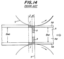
- Fig. 14 illustrates a rolling state of a normal universal rolling which is not accompanied with the reduction of web width.
- there is no zone I because the reduction of web width is not performed.
- there is a zone similar to the zone I which is caused by correcting the inclination of flanges into positions perpendicular to the web, such a similar zone is out of the question because the reaction forces from the vertical rolls are very much smaller than those in the case being accompanied with the reduction of web width. Consequently, the web ha is free from reaction forces in directions of web width so that there is no problem described above. It is therefore meaningless to shift the vertical rolls in the case shown in Fig. 14.
- Japanese Patent Application Laid-open No. 61-5,601 discloses a rolling method in which vertical rolls of a universal mill are shifted.
- this method does not aim at the rolling accompanied with the reduction of web width. Therefore, this method has only an effect to prevent webs from waving in rolling for producing H-beams having very thin webs.
- H-beams of typical nominal dimensions H750 ⁇ 200, H600 ⁇ 200 and H450 ⁇ 200 having various web thicknesses of 6 to 16 mm were produced by rolling in a manner reducing web widths. Rolling conditions of the produced H-beams were inspected.
- Fig. 15 having the abscissa indicating ⁇ Bw ⁇ Bw/Tw and the ordinate indicating ⁇ C/Tw, where Tw (mm) is web thickness before finishing rolling, Bw (mm) is inner web width, ⁇ Bw is rolling reduction of inner web width, and ⁇ C/Tw is increase of deflection of web center.
- marks ⁇ and ⁇ indicate the results of the prior art methods, while marks ⁇ and ⁇ indicate the results of the method according to the invention whose vertical rolls were 20 mm shifted onto the downstream side.
- the marks ⁇ and ⁇ show the fact that flaws occurred in web surfaces, and marks ⁇ and ⁇ show flawless surfaces of webs.
- the limitation of ⁇ C/Tw in ordinate in Fig. 15 is 0.33.
- the horizontal rolls of the finishing mills are positively driven and the vertical rolls are idlers and driven by movements of the billets.
- this method is applicable to a finishing mill whose vertical rolls are driven and the horizontal rolls are idlers or both the vertical and horizontal rolls are driven, so long as the rolling is accompanied with reduction of inner web widths.
- adjustable width rolls which are known as disclosed, for example, in Japanese Patent Application Laid-open No. 1-317,607 are used as horizontal rolls provided for rolling H-beams of various sizes.
- a billet rolled in rough rolling is rolled by a universal finishing mill whose both vertical rolls and horizontal rolls are positively driven.
- the vertical rolls of the universal mill are positively driven so that the flanges hb and the web ha of a billet h are positively driven to reduce the reaction forces Pf considerably.
- the limit value of rolling reduction of web widths can be greatly enlarged. Therefore, H-beams of various sizes can be rolled without increasing the number of rolling passes, and H-beams of constant web widths can be produced by adjusting rolling reduction of web widths even if widths of rolling rolls are changed due to wear of the rolls caused by increase of the number of rolled billets.
- H-beams of typical nominal dimensions H750x200, H600 ⁇ 200 and H450 ⁇ 200 having various web thicknesses of 6 to 16 mm were produced by rolling in a manner reducing web widths. Rolling conditions of the produced H-beams were inspected.
- Fig. 17 having the abscissa indicating ⁇ Bw ⁇ Bw/Tw and the ordinate indicating ⁇ C/Tw which are similar to those in Example 1 in Fig. 15.
- Marks ⁇ and ⁇ indicate the results of the prior art methods wherein horizontal rolls were positively driven without positively driving vertical rolls, while marks ⁇ and ⁇ indicate the results of the method according to the invention whose horizontal and vertical rolls were positively driven at substantially equal circumferential speeds.
- the marks ⁇ and ⁇ show the fact that flaws occurred in web surfaces, and marks ⁇ and ⁇ show flawless surfaces of webs.
- the limitation of ⁇ C/Tw in ordinate in Fig. 17 is 0.33.
- the horizontal rolls and the vertical rolls of the universal finishing mill are simultaneously positively driven.
- this method is applicable to a finishing mill whose vertical rolls are positively driven and the horizontal rolls are not positively driven, so long as the rolling is accompanied with reduction of inner web widths.
- adjustable width rolls which are known as disclosed, for example, in Japanese Patent Application Laid-open No. 1-317,607 are used as horizontal rolls provided for rolling H-beams of various sizes.
- horizontal rolls which are not adjustable in width so long as their widths are narrower than inner web widths of rough rolled billets and vertical rolls have a roll gap less than web widths of the rough rolled billets to reduce the inner web widths of the billets.
Landscapes
- Engineering & Computer Science (AREA)
- Mechanical Engineering (AREA)
- Metal Rolling (AREA)
- Reduction Rolling/Reduction Stand/Operation Of Reduction Machine (AREA)
Claims (6)
- Procédé pour fabriquer une poutrelle en H en faisant subir à une billette d'acier (7, h) ayant été dégrossie et pourvue d'une âme (ha) et d'ailes (hb) un laminage de finissage au moyen d'un laminoir finisseur universel comprenant une paire de cylindres verticaux (V) enserrant les ailes (hb) de la billette (7, h) sur les deux côtés et une paire de cylindres horizontaux (H) ayant une largeur inférieure à celle des cylindres du dégrossissage et enserrant l'âme (ha) sur les côtés supérieur et inférieur afin de réduire la largeur de l'âme et l'épaisseur des ailes (hb) de la billette (7, h) et de corriger l'inclinaison des ailes (hb), permettant ainsi de réduire et d'ajuster une largeur intérieure de l'âme de la poutrelle en H, caractérisé en ce que la billette (7, h) est laminée par le laminoir finisseur universel dans une condition telle que les axes (Z) de la paire de cylindres verticaux (V) soient décalés, de préférence de 3 à 30 mm, vers le côté de l'aval du laminoir finisseur, par rapport aux axes (Y) de la paire de cylindres horizontaux, de manière à obtenir le chevauchement d'une zone (K) réduisant une épaisseur de l'âme (ha) et d'une zone (I) réduisant une largeur intérieure de l'âme.
- Procédé selon la revendication 1, caractérisé en ce que les axes (Y) de la paire de cylindres horizontaux sont décalés vers le côté de l'amont par rapport aux axes (Z) de la paire de cylindres verticaux (V).
- Procédé pour fabriquer une poutrelle en H en faisant subir à une billette d'acier (7, h) ayant été dégrossie et pourvue d'une âme (ha) et d'ailes (hb) un laminage de finissage au moyen d'un laminoir finisseur universel comprenant une paire de cylindres verticaux (V) enserrant les ailes (hb) de la billette (7, h) sur les deux côtés et une paire de cylindres horizontaux (H) ayant une largeur inférieure à celle des cylindres du dégrossissage et enserrant l'âme (ha) sur les côtés supérieur et inférieur afin de réduire la largeur de l'âme et l'épaisseur des ailes (hb) de la billette (7, h) et de corriger l'inclinaison des ailes (hb), permettant ainsi de réduire et d'ajuster une largeur intérieure de l'âme de la poutrelle en H, caractérisé en ce que la billette (7, h) est laminée par le laminoir finisseur universel dont la paire de cylindres verticaux (V) est entraînée directement.
- Procédé selon la revendication 3, caractérisé en ce que la paire de cylindres verticaux (V) et la paire de cylindres horizontaux (H) sont toutes les deux entraînées directement.
- Procédé selon la revendication 4, caractérisé en ce que la paire de cylindres verticaux (V) est entraînée de manière à ce que leur vitesse circonférentielle soit sensiblement égale à celle de la paire de cylindres horizontaux (H).
- Procédé selon la revendication 1, caractérisé en ce que la billette (7, h) est laminée par le laminoir finisseur universel dont la paire de cylindres verticaux (V) est entraînée directement.
Applications Claiming Priority (4)
| Application Number | Priority Date | Filing Date | Title |
|---|---|---|---|
| JP297163/90 | 1990-11-05 | ||
| JP29716390A JPH04172102A (ja) | 1990-11-05 | 1990-11-05 | H形鋼の圧延方法 |
| JP330621/90 | 1990-11-30 | ||
| JP33062190A JPH04200901A (ja) | 1990-11-30 | 1990-11-30 | H型鋼の圧延方法 |
Publications (3)
| Publication Number | Publication Date |
|---|---|
| EP0484854A2 EP0484854A2 (fr) | 1992-05-13 |
| EP0484854A3 EP0484854A3 (en) | 1993-03-03 |
| EP0484854B1 true EP0484854B1 (fr) | 1996-07-17 |
Family
ID=26561026
Family Applications (1)
| Application Number | Title | Priority Date | Filing Date |
|---|---|---|---|
| EP91118768A Expired - Lifetime EP0484854B1 (fr) | 1990-11-05 | 1991-11-04 | Procédé pour le laminage de poutrelles en H |
Country Status (3)
| Country | Link |
|---|---|
| US (1) | US5203193A (fr) |
| EP (1) | EP0484854B1 (fr) |
| DE (2) | DE484854T1 (fr) |
Families Citing this family (10)
| Publication number | Priority date | Publication date | Assignee | Title |
|---|---|---|---|---|
| US5704998A (en) * | 1990-10-24 | 1998-01-06 | Consolidated Metal Products, Inc. | Hot rolling high-strength steel structural members |
| GB2280395B (en) * | 1992-03-27 | 1996-05-01 | Kawasaki Steel Co | Method for detecting setting errors of clearance between rollers in universal rolling mill, and method for rolling h-shaped steel having favourable flange dim |
| JP2589660B2 (ja) * | 1994-05-30 | 1997-03-12 | 川崎重工業株式会社 | ユニバーサル圧延機 |
| US5823042A (en) * | 1997-03-14 | 1998-10-20 | J&L Structural, Inc. | Method of making an improved hot rolled I-beam and associated product |
| RU2152831C2 (ru) * | 1997-12-30 | 2000-07-20 | Акционерное общество "Кузнецкий металлургический комбинат" | Способ прокатки фланцевых профилей в черновых калибрах |
| US6852181B2 (en) * | 2001-10-23 | 2005-02-08 | Consolidated Metal Products, Inc. | Flattened U-bolt and method |
| FR2864200B1 (fr) * | 2003-12-18 | 2006-03-10 | Airbus France | Procede pour soyer un profile et un profile soye selon ce procede |
| RU2294246C1 (ru) * | 2005-07-27 | 2007-02-27 | Открытое акционерное общество "Новокузнецкий металлургический комбинат" | Способ прокатки крупных швеллеров в черновых калибрах |
| JP6441159B2 (ja) * | 2015-04-27 | 2018-12-19 | 三菱重工業株式会社 | 圧延加工装置 |
| CN113828633B (zh) * | 2021-09-23 | 2024-01-19 | 山东钢铁股份有限公司 | 一种宽翼缘h型钢轧制方法 |
Family Cites Families (10)
| Publication number | Priority date | Publication date | Assignee | Title |
|---|---|---|---|---|
| JPS55126311A (en) * | 1979-03-22 | 1980-09-30 | Nippon Steel Corp | Controlling method for shape in universal rolling |
| JPS59202101A (ja) * | 1983-05-04 | 1984-11-15 | Nippon Steel Corp | フランジを有する形材の圧延方法 |
| JPS615601A (ja) * | 1984-06-20 | 1986-01-11 | Nec Corp | アンテナ追尾装置 |
| JP2553884B2 (ja) * | 1987-08-17 | 1996-11-13 | マスプロ電工株式会社 | アンテナ支持具 |
| JPH01317607A (ja) * | 1988-06-16 | 1989-12-22 | Kawasaki Steel Corp | 幅可変圧延ロール |
| JP2548377B2 (ja) * | 1988-06-29 | 1996-10-30 | 川崎製鉄株式会社 | H形鋼の圧延方法 |
| DE3821990A1 (de) * | 1988-06-30 | 1990-01-11 | Schloemann Siemag Ag | Regelung fuer profilstrassen |
| JPH0813361B2 (ja) * | 1988-09-20 | 1996-02-14 | 住友金属工業株式会社 | 平行フランジ形鋼の圧延方法 |
| JPH0289502A (ja) * | 1988-09-27 | 1990-03-29 | Kawasaki Steel Corp | 形鋼の圧延方法およびその圧延機列 |
| JPH02147112A (ja) * | 1988-11-28 | 1990-06-06 | Sumitomo Metal Ind Ltd | H形鋼のウエブ高さ制御圧延方法と装置 |
-
1991
- 1991-11-04 US US07/787,126 patent/US5203193A/en not_active Expired - Fee Related
- 1991-11-04 DE DE91118768T patent/DE484854T1/de active Pending
- 1991-11-04 EP EP91118768A patent/EP0484854B1/fr not_active Expired - Lifetime
- 1991-11-04 DE DE69120895T patent/DE69120895T2/de not_active Expired - Fee Related
Also Published As
| Publication number | Publication date |
|---|---|
| EP0484854A2 (fr) | 1992-05-13 |
| EP0484854A3 (en) | 1993-03-03 |
| DE69120895T2 (de) | 1997-01-02 |
| US5203193A (en) | 1993-04-20 |
| DE484854T1 (de) | 1994-02-03 |
| DE69120895D1 (de) | 1996-08-22 |
Similar Documents
| Publication | Publication Date | Title |
|---|---|---|
| EP0498733B1 (fr) | Procédé pour laminer des profilés en acier | |
| EP0484854B1 (fr) | Procédé pour le laminage de poutrelles en H | |
| EP0142568B1 (fr) | Procede et dispositif de calandrage de sections comportant un rebord | |
| EP0756905B1 (fr) | Procede et ligne de laminage pour produire des profiles ayant des brides et une ame | |
| AU710014B2 (en) | Method of rolling deformed bar and roll for deformed bar | |
| US4367642A (en) | Method of producing H-beams | |
| KR100214730B1 (ko) | 에이치형 비임의 압연방법 | |
| GB2222796A (en) | Rolling method for parallel-flange steel shapes | |
| JP3309807B2 (ja) | 外周部の断面形状が円形の金属材の製造方法及びその製造装置 | |
| JP3310427B2 (ja) | H形鋼の圧延方法 | |
| JP3520646B2 (ja) | 形鋼の製造方法 | |
| JP3496554B2 (ja) | 溝形鋼の製造方法、粗ユニバーサル圧延機および仕上ユニバーサル圧延機 | |
| EP0760263B1 (fr) | Procede et dispositif de laminage a chaud d'acier a profil en h | |
| AU681219B2 (en) | H-steel manufacturing method | |
| JPH0364201B2 (fr) | ||
| JP3098877B2 (ja) | H形鋼の圧延方法 | |
| JP3272856B2 (ja) | フランジを有する形鋼の圧延方法 | |
| JP2661475B2 (ja) | H形鋼のウェブ中心偏りの制御圧延方法 | |
| JP3389831B2 (ja) | 溝形鋼の圧延法 | |
| JP2626330B2 (ja) | H形鋼圧延用エッジャー圧延機 | |
| JP3027504B2 (ja) | フランジを有する形材の圧延方法 | |
| JP2025151468A (ja) | 鋼矢板の製造方法 | |
| JPH11314101A (ja) | H形鋼の圧延方法 | |
| JP2973859B2 (ja) | H形鋼のフランジ幅制御方法 | |
| CA1247405A (fr) | Methode et dispositif de laminage pour la mise en forme de sections a bride |
Legal Events
| Date | Code | Title | Description |
|---|---|---|---|
| PUAI | Public reference made under article 153(3) epc to a published international application that has entered the european phase |
Free format text: ORIGINAL CODE: 0009012 |
|
| AK | Designated contracting states |
Kind code of ref document: A2 Designated state(s): DE GB LU |
|
| PUAL | Search report despatched |
Free format text: ORIGINAL CODE: 0009013 |
|
| AK | Designated contracting states |
Kind code of ref document: A3 Designated state(s): DE GB LU |
|
| 17P | Request for examination filed |
Effective date: 19930719 |
|
| DET | De: translation of patent claims | ||
| 17Q | First examination report despatched |
Effective date: 19940819 |
|
| GRAH | Despatch of communication of intention to grant a patent |
Free format text: ORIGINAL CODE: EPIDOS IGRA |
|
| GRAH | Despatch of communication of intention to grant a patent |
Free format text: ORIGINAL CODE: EPIDOS IGRA |
|
| GRAA | (expected) grant |
Free format text: ORIGINAL CODE: 0009210 |
|
| AK | Designated contracting states |
Kind code of ref document: B1 Designated state(s): DE GB LU |
|
| REF | Corresponds to: |
Ref document number: 69120895 Country of ref document: DE Date of ref document: 19960822 |
|
| PLBE | No opposition filed within time limit |
Free format text: ORIGINAL CODE: 0009261 |
|
| STAA | Information on the status of an ep patent application or granted ep patent |
Free format text: STATUS: NO OPPOSITION FILED WITHIN TIME LIMIT |
|
| 26N | No opposition filed | ||
| REG | Reference to a national code |
Ref country code: GB Ref legal event code: IF02 |
|
| PGFP | Annual fee paid to national office [announced via postgrant information from national office to epo] |
Ref country code: GB Payment date: 20031029 Year of fee payment: 13 |
|
| PGFP | Annual fee paid to national office [announced via postgrant information from national office to epo] |
Ref country code: LU Payment date: 20031112 Year of fee payment: 13 |
|
| PGFP | Annual fee paid to national office [announced via postgrant information from national office to epo] |
Ref country code: DE Payment date: 20031113 Year of fee payment: 13 |
|
| PG25 | Lapsed in a contracting state [announced via postgrant information from national office to epo] |
Ref country code: LU Free format text: LAPSE BECAUSE OF NON-PAYMENT OF DUE FEES Effective date: 20041104 Ref country code: GB Free format text: LAPSE BECAUSE OF NON-PAYMENT OF DUE FEES Effective date: 20041104 |
|
| PG25 | Lapsed in a contracting state [announced via postgrant information from national office to epo] |
Ref country code: DE Free format text: LAPSE BECAUSE OF NON-PAYMENT OF DUE FEES Effective date: 20050601 |
|
| GBPC | Gb: european patent ceased through non-payment of renewal fee |
Effective date: 20041104 |