EP0623419A2 - Changeur automatique d'outil - Google Patents
Changeur automatique d'outil Download PDFInfo
- Publication number
- EP0623419A2 EP0623419A2 EP94303173A EP94303173A EP0623419A2 EP 0623419 A2 EP0623419 A2 EP 0623419A2 EP 94303173 A EP94303173 A EP 94303173A EP 94303173 A EP94303173 A EP 94303173A EP 0623419 A2 EP0623419 A2 EP 0623419A2
- Authority
- EP
- European Patent Office
- Prior art keywords
- swing arm
- machining
- tool bit
- shaft
- another
- Prior art date
- Legal status (The legal status is an assumption and is not a legal conclusion. Google has not performed a legal analysis and makes no representation as to the accuracy of the status listed.)
- Granted
Links
Images



Classifications
-
- B—PERFORMING OPERATIONS; TRANSPORTING
- B23—MACHINE TOOLS; METAL-WORKING NOT OTHERWISE PROVIDED FOR
- B23Q—DETAILS, COMPONENTS, OR ACCESSORIES FOR MACHINE TOOLS, e.g. ARRANGEMENTS FOR COPYING OR CONTROLLING; MACHINE TOOLS IN GENERAL CHARACTERISED BY THE CONSTRUCTION OF PARTICULAR DETAILS OR COMPONENTS; COMBINATIONS OR ASSOCIATIONS OF METAL-WORKING MACHINES, NOT DIRECTED TO A PARTICULAR RESULT
- B23Q3/00—Devices holding, supporting, or positioning work or tools, of a kind normally removable from the machine
- B23Q3/155—Arrangements for automatic insertion or removal of tools, e.g. combined with manual handling
- B23Q3/1552—Arrangements for automatic insertion or removal of tools, e.g. combined with manual handling parts of devices for automatically inserting or removing tools
- B23Q3/1554—Transfer mechanisms, e.g. tool gripping arms; Drive mechanisms therefore
-
- B—PERFORMING OPERATIONS; TRANSPORTING
- B23—MACHINE TOOLS; METAL-WORKING NOT OTHERWISE PROVIDED FOR
- B23Q—DETAILS, COMPONENTS, OR ACCESSORIES FOR MACHINE TOOLS, e.g. ARRANGEMENTS FOR COPYING OR CONTROLLING; MACHINE TOOLS IN GENERAL CHARACTERISED BY THE CONSTRUCTION OF PARTICULAR DETAILS OR COMPONENTS; COMBINATIONS OR ASSOCIATIONS OF METAL-WORKING MACHINES, NOT DIRECTED TO A PARTICULAR RESULT
- B23Q3/00—Devices holding, supporting, or positioning work or tools, of a kind normally removable from the machine
- B23Q3/155—Arrangements for automatic insertion or removal of tools, e.g. combined with manual handling
- B23Q3/1552—Arrangements for automatic insertion or removal of tools, e.g. combined with manual handling parts of devices for automatically inserting or removing tools
- B23Q3/1554—Transfer mechanisms, e.g. tool gripping arms; Drive mechanisms therefore
- B23Q2003/155414—Transfer mechanisms, e.g. tool gripping arms; Drive mechanisms therefore the transfer mechanism comprising two or more grippers
- B23Q2003/155418—Transfer mechanisms, e.g. tool gripping arms; Drive mechanisms therefore the transfer mechanism comprising two or more grippers the grippers moving together
-
- B—PERFORMING OPERATIONS; TRANSPORTING
- B23—MACHINE TOOLS; METAL-WORKING NOT OTHERWISE PROVIDED FOR
- B23Q—DETAILS, COMPONENTS, OR ACCESSORIES FOR MACHINE TOOLS, e.g. ARRANGEMENTS FOR COPYING OR CONTROLLING; MACHINE TOOLS IN GENERAL CHARACTERISED BY THE CONSTRUCTION OF PARTICULAR DETAILS OR COMPONENTS; COMBINATIONS OR ASSOCIATIONS OF METAL-WORKING MACHINES, NOT DIRECTED TO A PARTICULAR RESULT
- B23Q3/00—Devices holding, supporting, or positioning work or tools, of a kind normally removable from the machine
- B23Q3/155—Arrangements for automatic insertion or removal of tools, e.g. combined with manual handling
- B23Q3/1552—Arrangements for automatic insertion or removal of tools, e.g. combined with manual handling parts of devices for automatically inserting or removing tools
- B23Q3/1554—Transfer mechanisms, e.g. tool gripping arms; Drive mechanisms therefore
- B23Q2003/155414—Transfer mechanisms, e.g. tool gripping arms; Drive mechanisms therefore the transfer mechanism comprising two or more grippers
- B23Q2003/155425—Transfer mechanisms, e.g. tool gripping arms; Drive mechanisms therefore the transfer mechanism comprising two or more grippers pivotable
- B23Q2003/155428—Transfer mechanisms, e.g. tool gripping arms; Drive mechanisms therefore the transfer mechanism comprising two or more grippers pivotable about a common axis
-
- B—PERFORMING OPERATIONS; TRANSPORTING
- B23—MACHINE TOOLS; METAL-WORKING NOT OTHERWISE PROVIDED FOR
- B23Q—DETAILS, COMPONENTS, OR ACCESSORIES FOR MACHINE TOOLS, e.g. ARRANGEMENTS FOR COPYING OR CONTROLLING; MACHINE TOOLS IN GENERAL CHARACTERISED BY THE CONSTRUCTION OF PARTICULAR DETAILS OR COMPONENTS; COMBINATIONS OR ASSOCIATIONS OF METAL-WORKING MACHINES, NOT DIRECTED TO A PARTICULAR RESULT
- B23Q3/00—Devices holding, supporting, or positioning work or tools, of a kind normally removable from the machine
- B23Q3/155—Arrangements for automatic insertion or removal of tools, e.g. combined with manual handling
- B23Q3/1552—Arrangements for automatic insertion or removal of tools, e.g. combined with manual handling parts of devices for automatically inserting or removing tools
- B23Q3/1554—Transfer mechanisms, e.g. tool gripping arms; Drive mechanisms therefore
- B23Q2003/155414—Transfer mechanisms, e.g. tool gripping arms; Drive mechanisms therefore the transfer mechanism comprising two or more grippers
- B23Q2003/155425—Transfer mechanisms, e.g. tool gripping arms; Drive mechanisms therefore the transfer mechanism comprising two or more grippers pivotable
- B23Q2003/155432—Transfer mechanisms, e.g. tool gripping arms; Drive mechanisms therefore the transfer mechanism comprising two or more grippers pivotable about different axes
-
- B—PERFORMING OPERATIONS; TRANSPORTING
- B23—MACHINE TOOLS; METAL-WORKING NOT OTHERWISE PROVIDED FOR
- B23Q—DETAILS, COMPONENTS, OR ACCESSORIES FOR MACHINE TOOLS, e.g. ARRANGEMENTS FOR COPYING OR CONTROLLING; MACHINE TOOLS IN GENERAL CHARACTERISED BY THE CONSTRUCTION OF PARTICULAR DETAILS OR COMPONENTS; COMBINATIONS OR ASSOCIATIONS OF METAL-WORKING MACHINES, NOT DIRECTED TO A PARTICULAR RESULT
- B23Q3/00—Devices holding, supporting, or positioning work or tools, of a kind normally removable from the machine
- B23Q3/155—Arrangements for automatic insertion or removal of tools, e.g. combined with manual handling
- B23Q3/1552—Arrangements for automatic insertion or removal of tools, e.g. combined with manual handling parts of devices for automatically inserting or removing tools
- B23Q3/1554—Transfer mechanisms, e.g. tool gripping arms; Drive mechanisms therefore
- B23Q2003/155414—Transfer mechanisms, e.g. tool gripping arms; Drive mechanisms therefore the transfer mechanism comprising two or more grippers
- B23Q2003/155425—Transfer mechanisms, e.g. tool gripping arms; Drive mechanisms therefore the transfer mechanism comprising two or more grippers pivotable
- B23Q2003/155435—Transfer mechanisms, e.g. tool gripping arms; Drive mechanisms therefore the transfer mechanism comprising two or more grippers pivotable and linearly movable
- B23Q2003/155446—Transfer mechanisms, e.g. tool gripping arms; Drive mechanisms therefore the transfer mechanism comprising two or more grippers pivotable and linearly movable with translation of the pivoting axis
-
- Y—GENERAL TAGGING OF NEW TECHNOLOGICAL DEVELOPMENTS; GENERAL TAGGING OF CROSS-SECTIONAL TECHNOLOGIES SPANNING OVER SEVERAL SECTIONS OF THE IPC; TECHNICAL SUBJECTS COVERED BY FORMER USPC CROSS-REFERENCE ART COLLECTIONS [XRACs] AND DIGESTS
- Y10—TECHNICAL SUBJECTS COVERED BY FORMER USPC
- Y10T—TECHNICAL SUBJECTS COVERED BY FORMER US CLASSIFICATION
- Y10T483/00—Tool changing
- Y10T483/10—Process
-
- Y—GENERAL TAGGING OF NEW TECHNOLOGICAL DEVELOPMENTS; GENERAL TAGGING OF CROSS-SECTIONAL TECHNOLOGIES SPANNING OVER SEVERAL SECTIONS OF THE IPC; TECHNICAL SUBJECTS COVERED BY FORMER USPC CROSS-REFERENCE ART COLLECTIONS [XRACs] AND DIGESTS
- Y10—TECHNICAL SUBJECTS COVERED BY FORMER USPC
- Y10T—TECHNICAL SUBJECTS COVERED BY FORMER US CLASSIFICATION
- Y10T483/00—Tool changing
- Y10T483/17—Tool changing including machine tool or component
- Y10T483/1733—Rotary spindle machine tool [e.g., milling machine, boring, machine, grinding machine, etc.]
- Y10T483/1748—Tool changer between spindle and matrix
- Y10T483/1752—Tool changer between spindle and matrix including tool holder pivotable about axis
- Y10T483/1755—Plural tool holders pivotable about common axis
- Y10T483/1764—Tool holders pivotable about plural nonparallel axes
-
- Y—GENERAL TAGGING OF NEW TECHNOLOGICAL DEVELOPMENTS; GENERAL TAGGING OF CROSS-SECTIONAL TECHNOLOGIES SPANNING OVER SEVERAL SECTIONS OF THE IPC; TECHNICAL SUBJECTS COVERED BY FORMER USPC CROSS-REFERENCE ART COLLECTIONS [XRACs] AND DIGESTS
- Y10—TECHNICAL SUBJECTS COVERED BY FORMER USPC
- Y10T—TECHNICAL SUBJECTS COVERED BY FORMER US CLASSIFICATION
- Y10T483/00—Tool changing
- Y10T483/17—Tool changing including machine tool or component
- Y10T483/1733—Rotary spindle machine tool [e.g., milling machine, boring, machine, grinding machine, etc.]
- Y10T483/1748—Tool changer between spindle and matrix
- Y10T483/1752—Tool changer between spindle and matrix including tool holder pivotable about axis
- Y10T483/1776—Tool changer between spindle and matrix including tool holder pivotable about axis including intermediate tool changer
-
- Y—GENERAL TAGGING OF NEW TECHNOLOGICAL DEVELOPMENTS; GENERAL TAGGING OF CROSS-SECTIONAL TECHNOLOGIES SPANNING OVER SEVERAL SECTIONS OF THE IPC; TECHNICAL SUBJECTS COVERED BY FORMER USPC CROSS-REFERENCE ART COLLECTIONS [XRACs] AND DIGESTS
- Y10—TECHNICAL SUBJECTS COVERED BY FORMER USPC
- Y10T—TECHNICAL SUBJECTS COVERED BY FORMER US CLASSIFICATION
- Y10T483/00—Tool changing
- Y10T483/17—Tool changing including machine tool or component
- Y10T483/1733—Rotary spindle machine tool [e.g., milling machine, boring, machine, grinding machine, etc.]
- Y10T483/1748—Tool changer between spindle and matrix
- Y10T483/1783—Tool changer between spindle and matrix including linearly translatable tool changer [e.g., shuttle, ram, etc.]
- Y10T483/1786—Plural tool holders
Definitions
- the present invention relates to a device for automatically exchanging tools between a main machining axis and a tool magazine.
- Such a device typically performs the following steps: gripping a tool bit, a used bit which has completed its job, disposed in the machining shaft; removing the used tool bit from the tapered hole of the machining shaft; exchanging the position of the used tool bit disposed on a line of the extension of the machining shaft with another tool bit to be used in the same position; inserting the another tool bit in the machining shaft; and releasing the hold on the machining shaft so that the machining shaft can rotate and move into an operating position.
- such a device tries to improve the machining efficiency by speeding up the steps by using hydraulic or mechanical transmission systems.
- the conventional device of this type suffered from the following problems.
- the tool bit exchanger device of the present invention was made to resolve the problems outlined above, and the purpose is to present a device which can be manufactured easily and able to perform exchanging of tool bits automatically and reliably.
- a device comprising: a support frame; a rotating shaft having a swing arm having a gripper device freely rotatably disposed on the support frame; another rotating shaft having another swing arm having another gripper device freely rotatably disposed on the support frame; and a driving device for operating the swing arms so as to remove one tool bit from a machining shaft disposed on a machining center with one gripper device of the swing arm and simultaneously installing another tool bit with another gripper device of the another swing arm in a vacated the machining shaft disposed on the machining center.
- a feature of the device is that an output shaft of the driving device has a bevel gear to engage with a follower bevel gear disposed on the rotating shaft and with another follower gear disposed on the another rotating shaft.
- a feature of the device is that the one rotating shaft and the another rotating shaft is separated by a 90 degree separation angle.
- a modification of the device of the present invention is that the driving device for operating the swing arms is provided individually on each of the one rotating shaft and the another rotating shaft.
- the device presented above has a pair of rotation shafts each of which is provided with a swing arm having a set of gripper devices.
- the swing arms can be rotated freely without interfering with each otherso that the tool bit used for machining disposed on the machining shaft of the machine center is removed by one set of grippers disposed on one swing arm and simultaneously the other set of grippers disposed on the other swing arm installed a new tool bit on the vacated machining shaft of the machining center.
- a modification of the device is also presented such that the driving device is provided individually on each of the rotation shafts of the device of the present invention.
- the device of such a construction is advantages compared with the conventional devices for automatic changing of tool bits because the steps required in the conventional devices: removing the tool bit from the machining shaft; switching the used tool bit with a new tool bit; installing the new tool bit in the machining shaft of the machining center; are eliminated and replaced with one step of simultaneously removing the used tool bit from the machining shaft and installing the new tool bit and in the machining shaft of the machining center. Therefore, the entire operation of exchanging the tool bits is carried out efficiently to improve the machining operation of the machining center.
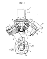
- a tool exchanger device A in Figure 1 is a device for automatically exchanging tool bits, and comprises a support frame 1 and a driving mechanism 2 firmly fixed on the support frame 1 as well as the rotating shafts 3, 4 supported by the bearings la, lb.
- the driving mechanism 2 comprises electric and hydraulic motors, and associated actuators.
- a bevel gear 5 having a bearing Ic is attached to the bottom end of an output shaft 2a by a fixing device 2b.
- the pair of rotating shafts 3, 4 are disposed symmetrically on the left and right sides of the output shaft 2a, and the extension lines from the centers of the rotating shafts 3, 4 cross each other at the extension line of the center line of the output shaft 2a at the base of the output shaft 2a of the bevel gear 5.
- Swing arms 8, 9 having a 90 degree separation angle are fixed to the rotating shaft 3, 4 respectively by fixing devices 3b, 4b (4b is not shown).
- Each swing arm 8, 9 is respectively provided with a set of gripper device 11, 12 at its free end for grasping a tool bit 10.
- the swing arms 8, 9 with the gripper devices 11, 12 are disposed symmetrically, and are driven by the driving device 2.
- the motions of the swing arms 8, 9 are as follows: they rotate 90 degrees simultaneously within a plane about the machining shaft 21 of a machining center B; resulting in that one of the swing arm 8 removes the gripper devices 11 from the operating position (the position of the swing arm 8 in Figure 1) to a stand-by position (the position of the swing arm 9 in Figure 1) at the same time as the swing arm 9 moves the gripper device 12 from the stand-by position to the operating position.
- the designs of the gripper devices 11, 12 are known, as are the hooks 11 a, 12a which elastically hold the tool bit 10.
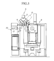
- the tool exchanger device A of the above configuration is disposed between a machining shaft 21 and a tool magazine 22 of a machining center B, as shown in Figures 5 and 6.
- the support frame 1 is attached to a guide rod 23, as shown in Figure 6, and in freely movable in the directions of X- and Y-axis.
- the machining shaft 21 is freely movable in the Z-axis direction.
- the X-axis direction is left/right
- the Y-axis direction is up/down
- the Z-axis direction is at right angles to the plane of the paper in Figure 5.
- the tool magazine 22 shown in Figure 6 comprises an endless chain 24 having a plurality of links provided with tool holder (not shown), driven by pulleys 25, 26 and 27.
- the tool magazine 22 rotates the new tool bit 10', held in the tool bit holder with the tool bit lying in the X-axis direction.
- the tool magazine 22 also rotates the tool pots, which serve as the shell for the shank part of tool bit 10', 90 degrees in the horizontal direction so as to orient the tool bit axis in the Z-axis direction at the pulley 25. This is shown at D in Figure 5.
- the machining center B is a known conventional type.
- a tool bit 10 (new or used) is installed on the gripper devices 11 of the swing arm 8 or the gripper device 12 of the swing arms 9 by the following steps.
- the device A is moved in the X-axis direction from the stand-by position relative to the machining shaft21 orthe tool magazine 22.
- Eitherthe gripper devices 11 of the swing arm 8 or the gripper device 12 of the swing arm 9 is disposed directly above the machining shaft 21 which has been moved to the first exchange position C, or directly above the second exchange position D of the tool bit 10 taken out of the tool magazine 22 and disposed so that its shaft lies parallel to the machining shaft 21.
- the device A is then lowered relative to the machining shaft 21 or to the tool bit 10 of the tool magazine 22.
- the tool bit 10 of the tool magazine 22 held in the gripper devices 11,12 is oriented in the Z-axis direction by the rotation of the holding device of the endless chain 24.
- the device A When the tool bit 10 (new or used) is to be removed from the gripper devices 11, 12, the device A is raised vertically relative to the machining shaft 21 when the tool bits 10 held in the gripper devices 11, 12 are attached to the machining shaft 21 or to the tool magazine 22.
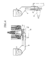
- a used tool bit 10 is first held in one grip 12 of the grippers devices 11, 12, for example, of the swing arm 9 folded to the bottom side, and then the driving device 2 is operated.
- the operation of the driving device 2 makes the swing arm 9, having the used tool bit 10 in its gripper device 12, swing upwards, thereby removing the used tool bit 10 from the tool magazine 22 and assumes a horizontal position.
- the swing arm 8, having an empty gripper device 11, rotates downward at the same time as the swing arm 9 rotates upwards.
- the device A is first raised upwards, and then the device A is moved in the X-axis direction to dispose the empty gripper device 11 of the swing arm 8 to a location above the machining shaft 21.
- the device A is then lowered to grip the used tool bit 10 disposed in the machining shaft 21 in the gripper device 11. This condition is illustrated in Figure 1.
- the driving device 2 is now driven in the reverse direction to the above preparatory step.
- the swing arm 8 is rotated upwards, thereby removing the used tool bit 10 from the machining shaft 21 and assumes a horizontal position.
- the other swing arm 9 rotates downward as the swing arm 8 is moving upwards, and installs a new tool bit 10' in the now vacated machining shaft 21.
- the device A is raised upwards away from the machining shaft 21 to remove the gripper device 11 from the new tool bit 10'.
- the machining center B is now ready to perform a machining operation using the new tool bit 10'.
- the used tool bit 10 disposed on the swing arm 8 is returned to the tool magazine 22, thereby completing the exchange operation.
- each tool bit is identified by the chain numbers of the tool magazine, and tool bit management is facilitated.
- the tool pots are random with respect to the tool bits and the chain, and this arrangement is useful in shortening the preparation time for readying the next tool bit.
- the above embodiment is a case of driving two swing arms 8, 9 at the same speed with one driving device 2, and mechanical interference between the two swing arms 8, 9 is avoided by positioning them suitably. It is also possible to avoid interferences by delaying the starting times for one swing arm relative to the other swing arm, by altering the speeds of the swing arms. Therefore, it is possible to avoid mechanical interferences by using the positional elements as well as chronological elements. However, as long as even a part of the operation of the swing arms 8, 9 is duplicated, such duplication times can be shortened, therefore, the meaning of simultaneous rotation, or rotating at the same time, includes the cases in which the rotations of the swing arms 8, 9 partly overlap each other.
Landscapes
- Engineering & Computer Science (AREA)
- Mechanical Engineering (AREA)
- Automatic Tool Replacement In Machine Tools (AREA)
Applications Claiming Priority (2)
| Application Number | Priority Date | Filing Date | Title |
|---|---|---|---|
| JP5107088A JP2518151B2 (ja) | 1993-05-07 | 1993-05-07 | 自動工具交換装置 |
| JP107088/93 | 1993-05-07 |
Publications (3)
| Publication Number | Publication Date |
|---|---|
| EP0623419A2 true EP0623419A2 (fr) | 1994-11-09 |
| EP0623419A3 EP0623419A3 (fr) | 1995-02-15 |
| EP0623419B1 EP0623419B1 (fr) | 1998-11-11 |
Family
ID=14450170
Family Applications (1)
| Application Number | Title | Priority Date | Filing Date |
|---|---|---|---|
| EP94303173A Expired - Lifetime EP0623419B1 (fr) | 1993-05-07 | 1994-04-29 | Changeur automatique d'outil |
Country Status (7)
| Country | Link |
|---|---|
| US (1) | US5439434A (fr) |
| EP (1) | EP0623419B1 (fr) |
| JP (1) | JP2518151B2 (fr) |
| KR (1) | KR100235911B1 (fr) |
| DE (1) | DE69414453T2 (fr) |
| ES (1) | ES2123097T3 (fr) |
| TW (1) | TW270096B (fr) |
Cited By (1)
| Publication number | Priority date | Publication date | Assignee | Title |
|---|---|---|---|---|
| EP1179387A1 (fr) * | 2000-08-08 | 2002-02-13 | GROB-Werke Dr. h.c. mult. Dipl.-Ing. Burkhart Grob e.K. | Machine outil pourvu d une pince d'outillage et/ou d un system de magasin d outil |
Families Citing this family (9)
| Publication number | Priority date | Publication date | Assignee | Title |
|---|---|---|---|---|
| JPH10263971A (ja) * | 1997-03-25 | 1998-10-06 | Brother Ind Ltd | 工作機械の工具交換装置 |
| US6416450B2 (en) * | 1999-07-28 | 2002-07-09 | Thermwood Corporation | Machine tool with improved tool changer means |
| JP2002210625A (ja) * | 2001-01-16 | 2002-07-30 | Mori Seiki Co Ltd | 工具交換装置の制御方法及び制御装置 |
| DE10118595B4 (de) * | 2001-04-12 | 2005-07-14 | Deckel Maho Seebach Gmbh | Werkzeugmaschine mit Werkzeugspindel und Werkzeugwechsler |
| DE20306087U1 (de) * | 2003-04-15 | 2003-06-12 | Hüller Hille GmbH, 71636 Ludwigsburg | Werkzeugmaschine mit Werkzeug-Magazin |
| US6991839B2 (en) * | 2004-05-20 | 2006-01-31 | Ward/Kraft, Inc. | Presentation folder formed from a laminate and process of using same |
| JP4789568B2 (ja) * | 2005-10-04 | 2011-10-12 | ヤマザキマザック株式会社 | 立形マシニングセンタ用ツールマガジン装置 |
| DE102019115715A1 (de) * | 2019-06-11 | 2020-12-17 | Gebr. Heller Maschinenfabrik Gmbh | Wechselvorrichtung zum Auswechseln von Werkzeugen und/oder Werkstücken |
| CN114559283B (zh) * | 2021-09-28 | 2023-03-10 | 马鞍山大晔精工有限公司 | 一种伞型刀库及其实施方法 |
Family Cites Families (8)
| Publication number | Priority date | Publication date | Assignee | Title |
|---|---|---|---|---|
| GB1255545A (en) * | 1968-05-07 | 1971-12-01 | Mitsubishi Heavy Ind Ltd | Machine tool including an automatic tool exchanger |
| US3608185A (en) * | 1969-04-10 | 1971-09-28 | Cincinnati Milacron Inc | Machine tool |
| US3619898A (en) * | 1969-08-11 | 1971-11-16 | Cincinnati Milling Machine Co | Machine tool |
| US3722711A (en) * | 1970-04-15 | 1973-03-27 | Cincinnati Milacron Inc | Machine tool |
| JPS5112476A (ja) * | 1974-07-22 | 1976-01-31 | Toshiba Machine Co Ltd | Jidokogukokansochi |
| SU657954A1 (ru) * | 1977-03-23 | 1979-04-25 | Ульяновское Головное Специальное Конструкторское Бюро Тяжелых И Фрезерных Станков | Устройство дл автоматической смены инструмента |
| US4575918A (en) * | 1984-06-29 | 1986-03-18 | Kearney & Trecker Corporation | Tool change mechanism |
| JP3009160B2 (ja) * | 1989-10-26 | 2000-02-14 | 豊田工機株式会社 | 工具交換装置を備えた工作機械 |
-
1993
- 1993-05-07 JP JP5107088A patent/JP2518151B2/ja not_active Expired - Lifetime
-
1994
- 1994-04-29 ES ES94303173T patent/ES2123097T3/es not_active Expired - Lifetime
- 1994-04-29 EP EP94303173A patent/EP0623419B1/fr not_active Expired - Lifetime
- 1994-04-29 DE DE69414453T patent/DE69414453T2/de not_active Expired - Lifetime
- 1994-05-03 TW TW083103988A patent/TW270096B/zh not_active IP Right Cessation
- 1994-05-06 KR KR1019940009934A patent/KR100235911B1/ko not_active Expired - Fee Related
- 1994-05-06 US US08/238,891 patent/US5439434A/en not_active Expired - Lifetime
Cited By (3)
| Publication number | Priority date | Publication date | Assignee | Title |
|---|---|---|---|---|
| EP1179387A1 (fr) * | 2000-08-08 | 2002-02-13 | GROB-Werke Dr. h.c. mult. Dipl.-Ing. Burkhart Grob e.K. | Machine outil pourvu d une pince d'outillage et/ou d un system de magasin d outil |
| US6783484B2 (en) | 2000-08-08 | 2004-08-31 | Grob-Werke Dr. H.C. Mult. Dipl. -Ing. Burkhart Grob E.K. | Machine tool with gripper and/ or tool magazine system |
| US7175579B2 (en) | 2000-08-08 | 2007-02-13 | Grob-Werke Dr. H.C. Mult. Dipl.-Ing. Burkhart Grob E.K. | Machine tool with gripper and/or tool magazine system |
Also Published As
| Publication number | Publication date |
|---|---|
| EP0623419B1 (fr) | 1998-11-11 |
| DE69414453D1 (de) | 1998-12-17 |
| EP0623419A3 (fr) | 1995-02-15 |
| JPH06315841A (ja) | 1994-11-15 |
| JP2518151B2 (ja) | 1996-07-24 |
| KR100235911B1 (ko) | 1999-12-15 |
| US5439434A (en) | 1995-08-08 |
| DE69414453T2 (de) | 1999-04-29 |
| ES2123097T3 (es) | 1999-01-01 |
| TW270096B (fr) | 1996-02-11 |
Similar Documents
| Publication | Publication Date | Title |
|---|---|---|
| CN101758411B (zh) | 一种用于机床的换刀装置 | |
| KR100217948B1 (ko) | 머시닝 센터의 공구교환방법과 이를 수행하는 장치 | |
| JP4310626B2 (ja) | 機械加工ライン | |
| EP0623419A2 (fr) | Changeur automatique d'outil | |
| JPH01193153A (ja) | 割出し加工装置 | |
| CN110587350A (zh) | 一种自动换刀装置 | |
| US4516311A (en) | Machining centers | |
| KR102530303B1 (ko) | 5축 로봇아암을 이용한 cnc선반 가공시스템 | |
| JP2003211336A (ja) | 工作機械の自動工具交換装置 | |
| CN210818619U (zh) | 一种新型车铣复合加工中心刀库 | |
| CN210588323U (zh) | 一种旋转机械手多头换刀装置 | |
| KR101419055B1 (ko) | 공작기계의 자동 공구교환장치 | |
| JP2000126968A (ja) | 自動工具交換装置 | |
| JP4501299B2 (ja) | パンチプレス | |
| JPH0338006B2 (fr) | ||
| EP0258992A2 (fr) | Changeur d'outils automatique | |
| EP1080831B1 (fr) | Dispositif d'échange d'outils pour machine-outils | |
| KR20220169107A (ko) | Cnc선반용 소재 적재장치 | |
| EP0462081B1 (fr) | Machine automatique pour insérer à force des éléments troués et formés sur un arbre | |
| EP0040012A1 (fr) | Changeur d'outil automatique pour tête porte-outil rotative avec chariot porte-outil à avance transversale | |
| JPH1199427A (ja) | 自動工具交換装置を備えた工作機械 | |
| KR810000032B1 (ko) | 가공센터에 착설하는 공구 자동교환 장치 | |
| CN216967100U (zh) | 一种机床换刀设备 | |
| KR810001768B1 (ko) | 공구 자동교환기가 있는 공작기계 | |
| KR920005307Y1 (ko) | 멀티스핀들 자동 구동장치 |
Legal Events
| Date | Code | Title | Description |
|---|---|---|---|
| PUAI | Public reference made under article 153(3) epc to a published international application that has entered the european phase |
Free format text: ORIGINAL CODE: 0009012 |
|
| AK | Designated contracting states |
Kind code of ref document: A2 Designated state(s): CH DE ES FR GB IT LI |
|
| PUAL | Search report despatched |
Free format text: ORIGINAL CODE: 0009013 |
|
| AK | Designated contracting states |
Kind code of ref document: A3 Designated state(s): CH DE ES FR GB IT LI |
|
| K1C1 | Correction of patent application (title page) published |
Effective date: 19941109 |
|
| RIN1 | Information on inventor provided before grant (corrected) |
Inventor name: TAMURA, YUKIO Inventor name: SATO, KYUICHI |
|
| 17P | Request for examination filed |
Effective date: 19950727 |
|
| 17Q | First examination report despatched |
Effective date: 19960119 |
|
| GRAG | Despatch of communication of intention to grant |
Free format text: ORIGINAL CODE: EPIDOS AGRA |
|
| GRAG | Despatch of communication of intention to grant |
Free format text: ORIGINAL CODE: EPIDOS AGRA |
|
| GRAH | Despatch of communication of intention to grant a patent |
Free format text: ORIGINAL CODE: EPIDOS IGRA |
|
| GRAH | Despatch of communication of intention to grant a patent |
Free format text: ORIGINAL CODE: EPIDOS IGRA |
|
| GRAA | (expected) grant |
Free format text: ORIGINAL CODE: 0009210 |
|
| AK | Designated contracting states |
Kind code of ref document: B1 Designated state(s): CH DE ES FR GB IT LI |
|
| REG | Reference to a national code |
Ref country code: CH Ref legal event code: NV Representative=s name: SCHMAUDER & PARTNER AG PATENTANWALTSBUERO Ref country code: CH Ref legal event code: EP |
|
| REF | Corresponds to: |
Ref document number: 69414453 Country of ref document: DE Date of ref document: 19981217 |
|
| ET | Fr: translation filed | ||
| REG | Reference to a national code |
Ref country code: ES Ref legal event code: FG2A Ref document number: 2123097 Country of ref document: ES Kind code of ref document: T3 |
|
| ITF | It: translation for a ep patent filed | ||
| PLBE | No opposition filed within time limit |
Free format text: ORIGINAL CODE: 0009261 |
|
| STAA | Information on the status of an ep patent application or granted ep patent |
Free format text: STATUS: NO OPPOSITION FILED WITHIN TIME LIMIT |
|
| 26N | No opposition filed | ||
| REG | Reference to a national code |
Ref country code: GB Ref legal event code: IF02 |
|
| REG | Reference to a national code |
Ref country code: GB Ref legal event code: 732E |
|
| REG | Reference to a national code |
Ref country code: CH Ref legal event code: PUE Owner name: NIIGATA MACHINERY COMPANY, INC. Free format text: NIIGATA ENGINEERING CO., LTD.#NO. 4-1, KASUMIGASEKI 1-CHOME#CHIYODA-KU, TOKYO 100 (JP) -TRANSFER TO- NIIGATA MACHINERY COMPANY, INC.#10-1, KAMATAHONCHO 1-CHOME#OHTA-KU, TOKYO (JP) Ref country code: CH Ref legal event code: NV Representative=s name: BOVARD AG PATENTANWAELTE |
|
| REG | Reference to a national code |
Ref country code: FR Ref legal event code: TP |
|
| REG | Reference to a national code |
Ref country code: ES Ref legal event code: PC2A |
|
| REG | Reference to a national code |
Ref country code: CH Ref legal event code: PUE Owner name: NIIGATA MACHINE TECHNO CO. LTD. Free format text: NIIGATA MACHINERY COMPANY, INC.#10-1, KAMATAHONCHO 1-CHOME#OHTA-KU, TOKYO (JP) -TRANSFER TO- NIIGATA MACHINE TECHNO CO. LTD.#1300, OKAYAMA NIIGATA-SHI#NIIGATA-KEN (JP) |
|
| REG | Reference to a national code |
Ref country code: GB Ref legal event code: 732E |
|
| REG | Reference to a national code |
Ref country code: FR Ref legal event code: TP |
|
| REG | Reference to a national code |
Ref country code: ES Ref legal event code: PC2A |
|
| PGFP | Annual fee paid to national office [announced via postgrant information from national office to epo] |
Ref country code: FR Payment date: 20090428 Year of fee payment: 16 |
|
| PGFP | Annual fee paid to national office [announced via postgrant information from national office to epo] |
Ref country code: CH Payment date: 20090421 Year of fee payment: 16 |
|
| REG | Reference to a national code |
Ref country code: CH Ref legal event code: PL |
|
| REG | Reference to a national code |
Ref country code: FR Ref legal event code: ST Effective date: 20101230 |
|
| PG25 | Lapsed in a contracting state [announced via postgrant information from national office to epo] |
Ref country code: LI Free format text: LAPSE BECAUSE OF NON-PAYMENT OF DUE FEES Effective date: 20100430 Ref country code: CH Free format text: LAPSE BECAUSE OF NON-PAYMENT OF DUE FEES Effective date: 20100430 |
|
| PGFP | Annual fee paid to national office [announced via postgrant information from national office to epo] |
Ref country code: ES Payment date: 20110413 Year of fee payment: 18 Ref country code: DE Payment date: 20110224 Year of fee payment: 18 |
|
| PGFP | Annual fee paid to national office [announced via postgrant information from national office to epo] |
Ref country code: GB Payment date: 20110415 Year of fee payment: 18 |
|
| PGFP | Annual fee paid to national office [announced via postgrant information from national office to epo] |
Ref country code: IT Payment date: 20110420 Year of fee payment: 18 |
|
| REG | Reference to a national code |
Ref country code: DE Ref legal event code: R082 Ref document number: 69414453 Country of ref document: DE Representative=s name: PATENTANWAELTE OSTRIGA, SONNET, WIRTHS & VORWE, DE |
|
| PG25 | Lapsed in a contracting state [announced via postgrant information from national office to epo] |
Ref country code: FR Free format text: LAPSE BECAUSE OF NON-PAYMENT OF DUE FEES Effective date: 20100430 |
|
| GBPC | Gb: european patent ceased through non-payment of renewal fee |
Effective date: 20120429 |
|
| PG25 | Lapsed in a contracting state [announced via postgrant information from national office to epo] |
Ref country code: GB Free format text: LAPSE BECAUSE OF NON-PAYMENT OF DUE FEES Effective date: 20120429 |
|
| REG | Reference to a national code |
Ref country code: DE Ref legal event code: R119 Ref document number: 69414453 Country of ref document: DE Effective date: 20121101 |
|
| PG25 | Lapsed in a contracting state [announced via postgrant information from national office to epo] |
Ref country code: IT Free format text: LAPSE BECAUSE OF NON-PAYMENT OF DUE FEES Effective date: 20120429 |
|
| REG | Reference to a national code |
Ref country code: ES Ref legal event code: FD2A Effective date: 20130715 |
|
| PG25 | Lapsed in a contracting state [announced via postgrant information from national office to epo] |
Ref country code: ES Free format text: LAPSE BECAUSE OF NON-PAYMENT OF DUE FEES Effective date: 20120430 |
|
| PG25 | Lapsed in a contracting state [announced via postgrant information from national office to epo] |
Ref country code: DE Free format text: LAPSE BECAUSE OF NON-PAYMENT OF DUE FEES Effective date: 20121101 |