EP0623738A1 - Filtre de suie pour moteurs diesel - Google Patents
Filtre de suie pour moteurs diesel Download PDFInfo
- Publication number
- EP0623738A1 EP0623738A1 EP94101324A EP94101324A EP0623738A1 EP 0623738 A1 EP0623738 A1 EP 0623738A1 EP 94101324 A EP94101324 A EP 94101324A EP 94101324 A EP94101324 A EP 94101324A EP 0623738 A1 EP0623738 A1 EP 0623738A1
- Authority
- EP
- European Patent Office
- Prior art keywords
- filter device
- soot
- soot filter
- annular space
- wall
- Prior art date
- Legal status (The legal status is an assumption and is not a legal conclusion. Google has not performed a legal analysis and makes no representation as to the accuracy of the status listed.)
- Withdrawn
Links
Images

Classifications
-
- F—MECHANICAL ENGINEERING; LIGHTING; HEATING; WEAPONS; BLASTING
- F01—MACHINES OR ENGINES IN GENERAL; ENGINE PLANTS IN GENERAL; STEAM ENGINES
- F01N—GAS-FLOW SILENCERS OR EXHAUST APPARATUS FOR MACHINES OR ENGINES IN GENERAL; GAS-FLOW SILENCERS OR EXHAUST APPARATUS FOR INTERNAL-COMBUSTION ENGINES
- F01N3/00—Exhaust or silencing apparatus having means for purifying, rendering innocuous, or otherwise treating exhaust
- F01N3/02—Exhaust or silencing apparatus having means for purifying, rendering innocuous, or otherwise treating exhaust for cooling, or for removing solid constituents of, exhaust
- F01N3/021—Exhaust or silencing apparatus having means for purifying, rendering innocuous, or otherwise treating exhaust for cooling, or for removing solid constituents of, exhaust by means of filters
- F01N3/0212—Exhaust or silencing apparatus having means for purifying, rendering innocuous, or otherwise treating exhaust for cooling, or for removing solid constituents of, exhaust by means of filters with one or more perforated tubes surrounded by filtering material, e.g. filter candles
-
- F—MECHANICAL ENGINEERING; LIGHTING; HEATING; WEAPONS; BLASTING
- F01—MACHINES OR ENGINES IN GENERAL; ENGINE PLANTS IN GENERAL; STEAM ENGINES
- F01N—GAS-FLOW SILENCERS OR EXHAUST APPARATUS FOR MACHINES OR ENGINES IN GENERAL; GAS-FLOW SILENCERS OR EXHAUST APPARATUS FOR INTERNAL-COMBUSTION ENGINES
- F01N3/00—Exhaust or silencing apparatus having means for purifying, rendering innocuous, or otherwise treating exhaust
- F01N3/02—Exhaust or silencing apparatus having means for purifying, rendering innocuous, or otherwise treating exhaust for cooling, or for removing solid constituents of, exhaust
- F01N3/021—Exhaust or silencing apparatus having means for purifying, rendering innocuous, or otherwise treating exhaust for cooling, or for removing solid constituents of, exhaust by means of filters
- F01N3/022—Exhaust or silencing apparatus having means for purifying, rendering innocuous, or otherwise treating exhaust for cooling, or for removing solid constituents of, exhaust by means of filters characterised by specially adapted filtering structure, e.g. honeycomb, mesh or fibrous
-
- F—MECHANICAL ENGINEERING; LIGHTING; HEATING; WEAPONS; BLASTING
- F01—MACHINES OR ENGINES IN GENERAL; ENGINE PLANTS IN GENERAL; STEAM ENGINES
- F01N—GAS-FLOW SILENCERS OR EXHAUST APPARATUS FOR MACHINES OR ENGINES IN GENERAL; GAS-FLOW SILENCERS OR EXHAUST APPARATUS FOR INTERNAL-COMBUSTION ENGINES
- F01N3/00—Exhaust or silencing apparatus having means for purifying, rendering innocuous, or otherwise treating exhaust
- F01N3/02—Exhaust or silencing apparatus having means for purifying, rendering innocuous, or otherwise treating exhaust for cooling, or for removing solid constituents of, exhaust
- F01N3/021—Exhaust or silencing apparatus having means for purifying, rendering innocuous, or otherwise treating exhaust for cooling, or for removing solid constituents of, exhaust by means of filters
- F01N3/033—Exhaust or silencing apparatus having means for purifying, rendering innocuous, or otherwise treating exhaust for cooling, or for removing solid constituents of, exhaust by means of filters in combination with other devices
- F01N3/0335—Exhaust or silencing apparatus having means for purifying, rendering innocuous, or otherwise treating exhaust for cooling, or for removing solid constituents of, exhaust by means of filters in combination with other devices with exhaust silencers in a single housing
-
- F—MECHANICAL ENGINEERING; LIGHTING; HEATING; WEAPONS; BLASTING
- F01—MACHINES OR ENGINES IN GENERAL; ENGINE PLANTS IN GENERAL; STEAM ENGINES
- F01N—GAS-FLOW SILENCERS OR EXHAUST APPARATUS FOR MACHINES OR ENGINES IN GENERAL; GAS-FLOW SILENCERS OR EXHAUST APPARATUS FOR INTERNAL-COMBUSTION ENGINES
- F01N2230/00—Combination of silencers and other devices
- F01N2230/02—Exhaust filters
-
- F—MECHANICAL ENGINEERING; LIGHTING; HEATING; WEAPONS; BLASTING
- F01—MACHINES OR ENGINES IN GENERAL; ENGINE PLANTS IN GENERAL; STEAM ENGINES
- F01N—GAS-FLOW SILENCERS OR EXHAUST APPARATUS FOR MACHINES OR ENGINES IN GENERAL; GAS-FLOW SILENCERS OR EXHAUST APPARATUS FOR INTERNAL-COMBUSTION ENGINES
- F01N2330/00—Structure of catalyst support or particle filter
- F01N2330/06—Ceramic, e.g. monoliths
-
- F—MECHANICAL ENGINEERING; LIGHTING; HEATING; WEAPONS; BLASTING
- F01—MACHINES OR ENGINES IN GENERAL; ENGINE PLANTS IN GENERAL; STEAM ENGINES
- F01N—GAS-FLOW SILENCERS OR EXHAUST APPARATUS FOR MACHINES OR ENGINES IN GENERAL; GAS-FLOW SILENCERS OR EXHAUST APPARATUS FOR INTERNAL-COMBUSTION ENGINES
- F01N2470/00—Structure or shape of exhaust gas passages, pipes or tubes
- F01N2470/18—Structure or shape of exhaust gas passages, pipes or tubes the axis of inlet or outlet tubes being other than the longitudinal axis of apparatus
-
- F—MECHANICAL ENGINEERING; LIGHTING; HEATING; WEAPONS; BLASTING
- F02—COMBUSTION ENGINES; HOT-GAS OR COMBUSTION-PRODUCT ENGINE PLANTS
- F02B—INTERNAL-COMBUSTION PISTON ENGINES; COMBUSTION ENGINES IN GENERAL
- F02B3/00—Engines characterised by air compression and subsequent fuel addition
- F02B3/06—Engines characterised by air compression and subsequent fuel addition with compression ignition
-
- Y—GENERAL TAGGING OF NEW TECHNOLOGICAL DEVELOPMENTS; GENERAL TAGGING OF CROSS-SECTIONAL TECHNOLOGIES SPANNING OVER SEVERAL SECTIONS OF THE IPC; TECHNICAL SUBJECTS COVERED BY FORMER USPC CROSS-REFERENCE ART COLLECTIONS [XRACs] AND DIGESTS
- Y02—TECHNOLOGIES OR APPLICATIONS FOR MITIGATION OR ADAPTATION AGAINST CLIMATE CHANGE
- Y02T—CLIMATE CHANGE MITIGATION TECHNOLOGIES RELATED TO TRANSPORTATION
- Y02T10/00—Road transport of goods or passengers
- Y02T10/10—Internal combustion engine [ICE] based vehicles
- Y02T10/12—Improving ICE efficiencies
Definitions
- the invention relates to a soot filter device for diesel engines with a plurality of filter cartridges arranged in parallel in a cylindrical chamber, through the wall of which the exhaust gas passes from the inside to the inside, the exhaust gas being able to be conducted through an inlet connection piece into a prechamber which is in front of the filter candles and from which the Exhaust gas flows to the filter candles, and the soot layer which deposits on the outside of the filter candles can be burned off at intervals by hot air which can be generated by a hot air device.
- the object of the invention is to improve the sound absorption in soot filters of the type mentioned.
- the prechamber has two cylindrical coaxially arranged perforated plates which form an annular space between them, with a second annular space between the outer perforated plate and the chamber inner wall, which is separated at the end by a wall into which the inlet port flows.
- the two perforated plates arranged in the inlet area have a high soundproofing effect. It is particularly advantageous here if the size and / or number of holes in the inner perforated plate is different from those in the outer perforated plate. It is also advantageous if the front chamber wall on which the perforated sheets are located is closed. It is preferably proposed that the inlet connection is arranged tangentially or axially.
- the hot air device can also be connectable to the outside of the soot filter device.
- a particularly high sound insulation is achieved if a silencer is arranged inside the soot filter device in the flow direction behind the filter candles.
- the silencer can line the walls of the collecting space from which the outlet goes.
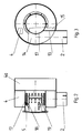
- the soot filter has a cylindrical housing 1, with a lateral tangentially or axially arranged inlet 2 and a coaxially arranged outlet 3.
- the inlet leads into an annular space 4 which surrounds two perforated plates 17, 18.
- the flame gases of a hot air device in particular an oil burner, are fed into the filter space 7, in which a larger number of filter candles 8 extend parallel to one another and axially parallel to the housing 1.
- the hot air device can be permanently attached to one end of the device or can be connected if necessary.
- the perforated plates 17, 18, which are arranged coaxially in the housing, are each cylindrical or tubular and each have one end fastened on the inside to the end of the housing which lies opposite the outlet 3.
- the inner perforated plate 18 is thus coaxially in the outer perforated plate 17, so that both perforated plates form an inner annular space 5 between them which, together with the outer annular space 4 and the interior 19 of the inner perforated plate 18, provides high sound insulation.
- the filter candles 8 are depth filters with ceramic windings 9 on perforated metal tubes 10.
- the tubes 10 are closed on the end facing the burner and open with the opposite ends in a collecting space 11, which can be surrounded by a silencer 12 the outlet 3 leads.
- the exhaust gases of the diesel engine pass through the inlet 2 into the annular space 4 and from there via an intermediate space 4a into the filter space 7. They flow through the filter space 7 and penetrate the cylindrical walls 8a of the filter candles 8 and then through the interior of the filter candles 8 to flow the collecting space 11 and to the outlet 3.
- the soot present in the exhaust gases settles in the ceramic windings 9 and on the outside as a layer which is not shown in the drawing.
- a guide plate 13 is attached tangentially to the cylindrical perforated wall of the combustion chamber 4a.
- the baffle 13 separates the area 14 of the annular space 4, into which the exhaust gases enter, from the area 15 of the annular space 4, into which the exhaust gases pass after the annular space has completely flowed through.
- the baffle plate 13 is positioned so obliquely to the impinging flow that the exhaust gas flow is led to the filter space 7 or to the expansion chamber.
Landscapes
- Engineering & Computer Science (AREA)
- Chemical & Material Sciences (AREA)
- Combustion & Propulsion (AREA)
- Mechanical Engineering (AREA)
- General Engineering & Computer Science (AREA)
- Processes For Solid Components From Exhaust (AREA)
- Exhaust Gas After Treatment (AREA)
Applications Claiming Priority (2)
| Application Number | Priority Date | Filing Date | Title |
|---|---|---|---|
| DE9301608U DE9301608U1 (de) | 1993-02-05 | 1993-02-05 | Rußfiltervorrichtung für Dieselmotoren |
| DE9301608U | 1993-05-05 |
Publications (1)
| Publication Number | Publication Date |
|---|---|
| EP0623738A1 true EP0623738A1 (fr) | 1994-11-09 |
Family
ID=6889022
Family Applications (1)
| Application Number | Title | Priority Date | Filing Date |
|---|---|---|---|
| EP94101324A Withdrawn EP0623738A1 (fr) | 1993-02-05 | 1994-01-29 | Filtre de suie pour moteurs diesel |
Country Status (2)
| Country | Link |
|---|---|
| EP (1) | EP0623738A1 (fr) |
| DE (1) | DE9301608U1 (fr) |
Cited By (1)
| Publication number | Priority date | Publication date | Assignee | Title |
|---|---|---|---|---|
| CN100526854C (zh) * | 2007-07-03 | 2009-08-12 | 武汉市天虹仪表有限责任公司 | 一种β射线烟尘浓度直读监测仪及其确认有效样本的方法 |
Citations (3)
| Publication number | Priority date | Publication date | Assignee | Title |
|---|---|---|---|---|
| DE8701816U1 (de) * | 1987-02-06 | 1987-04-09 | MAN Technologie GmbH, 8000 München | Partikelfilter für Verbrennungsmaschinen |
| EP0442318A2 (fr) * | 1990-02-16 | 1991-08-21 | Firma J. Eberspächer | Filtre à particules régénérable par combustion pour les gaz d'échappement de moteurs à combustion interne |
| DE4012411A1 (de) * | 1990-04-19 | 1991-10-24 | Webasto Ag Fahrzeugtechnik | Mit abgas einer brennkraftmaschine betreibbarer brenner zur regenerierung einer partikelfiltereinrichtung |
Family Cites Families (6)
| Publication number | Priority date | Publication date | Assignee | Title |
|---|---|---|---|---|
| DE1292669B (de) * | 1963-07-17 | 1969-04-17 | Aoi Katashi | Auspufftopf fuer Brennkraftmaschinen, insbesondere von Kraftfahrzeugen |
| DE2033775B2 (de) * | 1970-07-08 | 1978-06-08 | Prvni Brnenska Strojirna, Oborovy Podnik, Bruenn (Tschechoslowakei) | Dampfschalldampfer |
| US4180141A (en) * | 1975-11-24 | 1979-12-25 | Judd Frederick V H | Distributor for gas turbine silencers |
| DE2750960A1 (de) * | 1977-11-15 | 1979-05-17 | Daimler Benz Ag | Russfilter im abgasstrom von luftverdichtenden brennkraftmaschinen |
| DD140155A1 (de) * | 1978-11-16 | 1980-02-13 | Waldemar Ristau | Schalldaempfer |
| DE3538108A1 (de) * | 1985-10-26 | 1987-04-30 | Man Technologie Gmbh | Filter zum trennen von feststoffpartikeln aus diesel-abgasen |
-
1993
- 1993-02-05 DE DE9301608U patent/DE9301608U1/de not_active Expired - Lifetime
-
1994
- 1994-01-29 EP EP94101324A patent/EP0623738A1/fr not_active Withdrawn
Patent Citations (3)
| Publication number | Priority date | Publication date | Assignee | Title |
|---|---|---|---|---|
| DE8701816U1 (de) * | 1987-02-06 | 1987-04-09 | MAN Technologie GmbH, 8000 München | Partikelfilter für Verbrennungsmaschinen |
| EP0442318A2 (fr) * | 1990-02-16 | 1991-08-21 | Firma J. Eberspächer | Filtre à particules régénérable par combustion pour les gaz d'échappement de moteurs à combustion interne |
| DE4012411A1 (de) * | 1990-04-19 | 1991-10-24 | Webasto Ag Fahrzeugtechnik | Mit abgas einer brennkraftmaschine betreibbarer brenner zur regenerierung einer partikelfiltereinrichtung |
Cited By (1)
| Publication number | Priority date | Publication date | Assignee | Title |
|---|---|---|---|---|
| CN100526854C (zh) * | 2007-07-03 | 2009-08-12 | 武汉市天虹仪表有限责任公司 | 一种β射线烟尘浓度直读监测仪及其确认有效样本的方法 |
Also Published As
| Publication number | Publication date |
|---|---|
| DE9301608U1 (de) | 1993-03-25 |
Similar Documents
| Publication | Publication Date | Title |
|---|---|---|
| DE2953010C2 (fr) | ||
| DE69609324T2 (de) | Kombinierter wärmetauscher und schalldämpfer | |
| DE2303034A1 (de) | Auspufftopf fuer einen katalytischen reaktor zur reinigung von abgasen von verbrennungsmotoren | |
| WO1985004217A1 (fr) | Epurateur catalytique des gaz d'échappement de moteurs a combustion interne fonctionnant comme silencieux | |
| DE2107745A1 (de) | Abgasschalldampfer | |
| EP0315098B1 (fr) | Echangeur de chaleur pour chauffer des liquides | |
| DE10202005B4 (de) | Filtereinrichtung | |
| EP0549851A1 (fr) | Filtre à suie pour moteurs diesel | |
| EP0442318B1 (fr) | Filtre à particules régénérable par combustion pour les gaz d'échappement de moteurs à combustion interne | |
| EP0616833B1 (fr) | Filtre à suie pour moteurs diesel | |
| DE9301608U1 (de) | Rußfiltervorrichtung für Dieselmotoren | |
| DE2548540C3 (de) | Brennkammer für einen Flüssigkeitserhitzer | |
| EP0554499A1 (fr) | Filtre de la suie avec une chambre annulaire | |
| DE2418108A1 (de) | Rekuperative form einer thermisch/ katalytischen verbrennungsvorrichtung | |
| EP0451662B1 (fr) | Brûleur récupérateur | |
| DE802206C (de) | Akustischer Schalldaempfer fuer Brennkraftmaschinen mit Tangentialkraft-Funkenfaenger | |
| DE1021641B (de) | Zweiflutige Schalldaempferanordnung | |
| DE19933442A1 (de) | Partikelfilter mit einem Filtermedium und einem Katalysator | |
| EP2740913A1 (fr) | Système de traitement postérieur de gaz d'échappement | |
| AT20453B (de) | Schalldämpfer für Explosionskraftmaschinen. | |
| CH672177A5 (fr) | ||
| CH624733A5 (en) | Silencer for flowing gases, especially exhaust gases of internal combustion engines for vehicles | |
| DE971020C (de) | Heizgeraet mit einem Schwingbrenner als Waermequelle | |
| DE2856728A1 (de) | Einrichtung zur aussonderung von bleiteilchen aus den abgasen einer brennkraftmaschine | |
| DE29605597U1 (de) | Abgas-Wärmetauscher |
Legal Events
| Date | Code | Title | Description |
|---|---|---|---|
| PUAI | Public reference made under article 153(3) epc to a published international application that has entered the european phase |
Free format text: ORIGINAL CODE: 0009012 |
|
| AK | Designated contracting states |
Kind code of ref document: A1 Designated state(s): AT BE CH DE DK ES FR GB GR IE IT LI NL PT SE |
|
| 17P | Request for examination filed |
Effective date: 19941104 |
|
| 17Q | First examination report despatched |
Effective date: 19950303 |
|
| STAA | Information on the status of an ep patent application or granted ep patent |
Free format text: STATUS: THE APPLICATION HAS BEEN WITHDRAWN |
|
| 18W | Application withdrawn |
Withdrawal date: 19951031 |