EP0623745B1 - Schiebscheibenverdichter mit Schmiervorrichtung für Gleitschuh und Schiebscheibe - Google Patents
Schiebscheibenverdichter mit Schmiervorrichtung für Gleitschuh und Schiebscheibe Download PDFInfo
- Publication number
- EP0623745B1 EP0623745B1 EP94301704A EP94301704A EP0623745B1 EP 0623745 B1 EP0623745 B1 EP 0623745B1 EP 94301704 A EP94301704 A EP 94301704A EP 94301704 A EP94301704 A EP 94301704A EP 0623745 B1 EP0623745 B1 EP 0623745B1
- Authority
- EP
- European Patent Office
- Prior art keywords
- swash plate
- shoes
- pistons
- compressor
- cylinder
- Prior art date
- Legal status (The legal status is an assumption and is not a legal conclusion. Google has not performed a legal analysis and makes no representation as to the accuracy of the status listed.)
- Expired - Lifetime
Links
Images

Classifications
-
- F—MECHANICAL ENGINEERING; LIGHTING; HEATING; WEAPONS; BLASTING
- F04—POSITIVE - DISPLACEMENT MACHINES FOR LIQUIDS; PUMPS FOR LIQUIDS OR ELASTIC FLUIDS
- F04B—POSITIVE-DISPLACEMENT MACHINES FOR LIQUIDS; PUMPS
- F04B1/00—Multi-cylinder machines or pumps characterised by number or arrangement of cylinders
- F04B1/12—Multi-cylinder machines or pumps characterised by number or arrangement of cylinders having cylinder axes coaxial with, or parallel or inclined to, main shaft axis
- F04B1/14—Multi-cylinder machines or pumps characterised by number or arrangement of cylinders having cylinder axes coaxial with, or parallel or inclined to, main shaft axis having stationary cylinders
- F04B1/141—Details or component parts
- F04B1/146—Swash plates; Actuating elements
-
- F—MECHANICAL ENGINEERING; LIGHTING; HEATING; WEAPONS; BLASTING
- F04—POSITIVE - DISPLACEMENT MACHINES FOR LIQUIDS; PUMPS FOR LIQUIDS OR ELASTIC FLUIDS
- F04B—POSITIVE-DISPLACEMENT MACHINES FOR LIQUIDS; PUMPS
- F04B27/00—Multi-cylinder pumps specially adapted for elastic fluids and characterised by number or arrangement of cylinders
- F04B27/08—Multi-cylinder pumps specially adapted for elastic fluids and characterised by number or arrangement of cylinders having cylinders coaxial with, or parallel or inclined to, main shaft axis
- F04B27/10—Multi-cylinder pumps specially adapted for elastic fluids and characterised by number or arrangement of cylinders having cylinders coaxial with, or parallel or inclined to, main shaft axis having stationary cylinders
- F04B27/1036—Component parts, details, e.g. sealings, lubrication
- F04B27/1054—Actuating elements
-
- F—MECHANICAL ENGINEERING; LIGHTING; HEATING; WEAPONS; BLASTING
- F04—POSITIVE - DISPLACEMENT MACHINES FOR LIQUIDS; PUMPS FOR LIQUIDS OR ELASTIC FLUIDS
- F04B—POSITIVE-DISPLACEMENT MACHINES FOR LIQUIDS; PUMPS
- F04B27/00—Multi-cylinder pumps specially adapted for elastic fluids and characterised by number or arrangement of cylinders
- F04B27/08—Multi-cylinder pumps specially adapted for elastic fluids and characterised by number or arrangement of cylinders having cylinders coaxial with, or parallel or inclined to, main shaft axis
- F04B27/10—Multi-cylinder pumps specially adapted for elastic fluids and characterised by number or arrangement of cylinders having cylinders coaxial with, or parallel or inclined to, main shaft axis having stationary cylinders
- F04B27/1036—Component parts, details, e.g. sealings, lubrication
- F04B27/109—Lubrication
Definitions
- the present invention generally relates to a swash plate type refrigerant compressor and, more particularly, to a lubricating mechanism between the shoe and swash plate.
- a swash plate type refrigerant compressor suitable for use in an automotive air condition system is disclosed in, for example, US-A-4,568,252 to Ikeda et al.
- the Ikeda et al. swash plate compressor includes a pair of axially aligned front and rear cylinder blocks enclosed at both ends by front and rear housings. Valve plates are positioned between the respective cylinder blocks and the front and rear housings.
- the front and rear housings form suction chambers discharge chambers, and a plurality of aligned cylinder bores are arranged around the central axis of the cylinder blocks.
- Each of the cylinder bores have interconnecting suction chambers and discharge chambers formed in the front and rear housings.
- the cylinder blocks also have a central longitudinal bore formed therein.
- a drive shaft is rotatably mounted in the longitudinal bores.
- a swash plate chamber is formed between the cylinder blocks and a swash plate, keyed on the drive shaft, is rotatably received in the swash plate chamber.
- the swash plate rotates with the drive shaft and operatively engages double-headed pistons slidably fitted in the cylinder bores. More specifically, the swash plate is coupled to the pistons through shoes.
- the shoes provide a universal coupling allowing a reciprocatory compressing motion of the pistons within the cylinder bores in response to the rotation of the swash plate.
- the central portion of each of the double headed pistons is provided with a recess through which the swash plate passes during the rotation thereof, and a pair of spherical sockets to receive the shoes.
- Each of the shoes has a circular flat face in sliding contact with the oblique face of the swash plate and a half-spherical face in sliding engagement with the socket of the associated piston.
- the refrigerant gas which contains a lubricating oil
- the refrigerant gas which contains a lubricating oil
- the lubricating oil contained in the refrigerant gas lubricates the contacting surfaces of the shoes and the swash plate and respective sockets of the pistons.
- the circular flat surface of each shoe and the oblique surface of the swash plate are in close contact, sometimes an insufficient amount of lubricating oil is supplied to the contacting surfaces of the shoes and the swash plate.
- the insufficient or lack of lubrication can cause excessive frictional contact between the oblique face of the swash plate and the flat faces of the respective shoes, resulting in the generation of high temperatures, which can cause the contacting faces of the swash plate and shoes to seize.
- US-A-4781539 discloses a swash plate type refrigerant compressor which comprises a compressor housing enclosing therein a crank chamber, a suction chamber and a discharge chamber, the compressor housing including a cylinder block; a plurality of cylinder bores formed in the cylinder block; a piston slidably disposed within each of the cylinder bores, each of the pistons having a corresponding axis; a drive shaft rotatably supported in the cylinder block; a swash plate tiltably connected to the drive shaft and having a pair of sliding surfaces at axial sides thereof, the sliding surfaces having contacting surfaces where a plurality of pairs of shoes and the sliding surfaces engage, the shoes coupling the swash plate to the pistons so that the pistons may be driven in a reciprocating motion within the cylinder bores upon rotation of the swash plate; at least one lubricating means, in the form of a recessed portion, associated with at least one of the contacting surfaces of the swash plate for lubricating
- Figure 1 is a longitudinal sectional view of a swash plate refrigerant compressor.
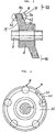
- Figure 2 is an enlarged cross-sectional view of a swash plate supported on a drive shaft and shoes engaging the swash plate in accordance with the present invention.
- Figure 3 is a side view of the swash plate, taken along the line VII-VII of Figure 2.
- a swash plate type compressor for background information only comprising a front cylinder block 1a and a rear cylinder block 1b together defining a combined cylinder block 1.
- a center bore 22 for receiving drive shaft 2 is formed through combined cylinder block 1.
- Drive shaft 2 is rotatably supported by a pair of anti-friction bearings 16 seated in center bore 22 of combined cylinder block 1.
- One end of drive shaft 2 projects from a front housing 15a, and via an electromagnetic clutch (not shown), is connectable to a vehicle engine so that a rotary drive force is transmitted from the engine to drive shaft 2 in response to energization of the electromagnetic clutch.
- a plurality of axially aligned cylinder bores 3 are formed in combined cylinder block 1.
- Each cylinder bore 3 has a front cylinder bore section formed in front cylinder block 1a and a rear cylinder bore section formed in rear cylinder block 1b, respectively.
- the front and rear cylinder bores are separated by swash plate chamber 4.
- Double headed piston 5, having front and rear piston heads, is slidably fitted in each cylinder bore 3 for reciprocation therein.
- a compression chamber 7 is formed in each cylinder bore 3 between front valve plate 10a and rear valve plate 10b, and the opposite ends of respective double headed pistons 5.
- Swash plate 6, having front and rear oblique faces inclined with respect to the axis of drive shaft 2 is fixedly mounted on drive shaft 2 for rotation within swash plate chamber 4.
- the front and rear oblique faces of swash plate 6 comprise front axial surface 19 and rear axial surface 20, which are in sliding contact with shoes 8.
- Shoes 8 are retained between swash plate 6 and pistons 5 so that, in response to the rotation of swash plate 6, pistons 5 reciprocate within cylinder bores 3.
- Each of double headed pistons 5 have front and rear piston heads 5a formed on the opposite ends thereof, and a cylindrical connecting portion 5c having therein a central recessed portion 5b for receiving shoes 8 as well as to permit rotation of swash plate 6 therethrough.
- central recessed portion 5c Within central recessed portion 5c is formed a pair of spherical sockets 9 for receiving shoes 8.
- Spherical sockets 9 and shoes 8 form a pair of ball-and-socket joints between front and rear piston heads 5a and front axial surface 19 and rear axial surface 20 of swash plate 6.
- Each of shoes 8 has a spherical portion 8a complementary with spherical socket 9 and circular flat face 8b in sliding contact with front axial surface 19 and rear axial surface 20 of swash plate 6.
- Front housing 15a and rear housing 15b close respective axial open ends of combined cylinder block 1.
- Front valve plate 10a and rear valve plate 10b are placed between front housing 15a and front cylinder block 1a and between rear housing 15b and rear cylinder block 1b, respectively.
- Annular suction chamber 17a and annular discharge chamber 18a are concentrically formed in front housing 15a in such a manner that both chambers 17a and 18a communicate with each cylinder bore 3.
- annular suction chamber 17b and annular discharge chamber 18b are concentrically formed in rear housing 15b in such a manner that both chambers 17b and 18b communicate with each cylinder bore 3.
- Discharge chambers 18a and 18b are arranged near the respective centers of front and rear housings 15a and 15b and are surrounded by associated suction chambers 17a and 17b, respectively.
- Suction ports 11a and 11b are formed in front and rear valve plates 10a and 10b, respectively, so as to provide a fluid communication between suction chambers 17a and 17b and each of cylinder bores 3 in response to the opening of suction valves 13a and 13b, respectively, during the intake stroke of the respective piston heads 5a.
- discharge ports 12a and 12b are formed in front and rear valve plates 10a and 10b, respectively, so as to provide a fluid communication between discharge chambers 18a and 18b and each of cylinder bores 3 in response to the opening of discharge valves 14a and 14b, respectively, during the compression stroke of the respective piston heads 5a.
- Refrigerant gas exiting an evaporator (not shown) of the air-conditioning circuit enters swash plate chamber 4 of the compressor through a suction conduit (not shown).
- the refrigerant gas then flows through the gap between drive shaft 2 and central bore 22, through anti-friction bearings 16, through passages 21 and into suction chamber 17a and 17b of front and rear housings 15a and 15b.
- the refrigerant in suction chambers 17a and 17b enters the plurality of cylinder bores 3 through suction ports 11a and 11b in response to successive opening of suction valves 13a and 13b caused by the cyclic pumping motions of piston heads 5a.
- the refrigerant pumped into the cylinder bores 3 is then compressed during the compressing stroke of the respective piston heads 5a.
- the compressed refrigerant gas is further forcibly sent into discharge chambers 18a and 18b through discharge ports 12a and 12b of valve plates 10a and 10b in response to the successive opening of discharge valves 14a and 14b during the cyclic compression stroke of respective piston heads 5a.
- the compressed refrigerant gas is then discharged to another element in the air-conditioning circuit, e.g., a condenser.
- FIGS 2 and 3 illustrate the present invention.
- An elastic member 50 in the shape of an annular ring is forcibly inserted into grooves 32 and 42.
- the axial surface of elastic member 50 preferably slightly projects beyond front axial surface 19 and rear axial surface 20. While, in the drawings, the width E of grooves 32 and 42 is depicted as being smaller than the diameter L of shoes 8, width E of grooves 32 and 42 can be larger than diameter L of shoes 8. Further, instead of using forcible insertion, elastic member 50 may be secured to grooves 32 and 42 by an adhesive material.
- Elastic member 50 is preferably able to contain lubricating oil, e.g., polytetrafluorothylene. According to the present invention shoes 8 smoothly slide on front axial surface 19 and rear axial surface 20 due to the lubricating effect of elastic member 50.
- the engaging surfaces between the swash plate and shoes are sufficiently lubricated by the lubricating oil, in the refrigerant gas.
- the lubricating oil in the refrigerant gas.
Landscapes
- Engineering & Computer Science (AREA)
- Mechanical Engineering (AREA)
- General Engineering & Computer Science (AREA)
- Compressors, Vaccum Pumps And Other Relevant Systems (AREA)
- Compressor (AREA)
Claims (2)
- Schiefscheibenkühlkompressor mit einem Kompressorgehäuse, das darin eine Kurbelkammer, eine Ansaugkammer (17a, 17b) und eine Auslaßkammer (18a, 18b) einschließt, wobei das Kompressorgehäuse einen Zylinderblock (1) enthält; einer Mehrzahl von in dem Zylinderblock gebildeten Zylinderbohrungen (3); einem innerhalb einer jeden der Zylinderbohrungen (3) gleitend verschiebbar vorgesehenen Kolben (5), wobei jeder Kolben (5) eine entsprechende Achse aufweist; einer drehbar in dem Zylinderblock (1) gelagerten Antriebswelle (2); einer kippbar mit der Antriebswelle (2) verbundenen Schiefscheibe (6), die ein Paar von Gleitoberflächen (19, 20) an axialen Seiten davon aufweist, wobei die Gleitoberflächen (19, 20) kontaktierende Oberflächen aufweisen, an denen eine Mehrzahl von Gleitschuhpaaren (8) und die Gleitoberflächen (19, 20) aneinander angreifen, die Gleitschuhe (8) die Schiefscheibe (6) mit den Kolben (5) so verbinden, daß die Kolben (5) auf die Rotation der Schiefscheibe (6) hin in eine Hin- und Herbewegung innerhalb der Zylinderbohrungen (3) angetrieben werden können; mindestens einem Schmiermittel (32, 42) in der Form eines ausgesparten Abschnittes (32, 42), das mit mindestens einer der kontaktierenden Oberfläche (19a, 20a) der Schiefscheibe (6) zur Schmierung zwischen den Gleitschuhen (8) und der Schiefscheibe (6) verknüpft ist,
dadurch gekennzeichnet, daß ein elastisches Teil (50), das aus einem Material gemacht ist, das mit einem Schmiermittel imprägniert werden kann, in dem ausgesparten Abschnitt (32, 42) positioniert ist. - Kompressor nach Anspruch 1, bei dem das Material Polytetrafluoräthylen ist.
Priority Applications (1)
| Application Number | Priority Date | Filing Date | Title |
|---|---|---|---|
| EP95114645A EP0688953B1 (de) | 1993-03-10 | 1994-03-10 | Schiefscheibenverdichter mit Schmiervorrichtung für Gleitschuh und Schiefscheibe |
Applications Claiming Priority (15)
| Application Number | Priority Date | Filing Date | Title |
|---|---|---|---|
| JP10140/93 | 1993-03-10 | ||
| JP1014093U JPH0669371U (ja) | 1993-03-10 | 1993-03-10 | 斜板式圧縮機 |
| JP10140/93U | 1993-03-10 | ||
| JP1075393U JPH0669373U (ja) | 1993-03-12 | 1993-03-12 | 斜板式圧縮機 |
| JP10753/93U | 1993-03-12 | ||
| JP10753/93 | 1993-03-12 | ||
| JP1209293U JPH0669374U (ja) | 1993-03-18 | 1993-03-18 | 斜板式圧縮機 |
| JP12092/93U | 1993-03-18 | ||
| JP12092/93 | 1993-03-18 | ||
| JP25710/93 | 1993-05-18 | ||
| JP25710/93U | 1993-05-18 | ||
| JP1993025710U JP2587484Y2 (ja) | 1993-05-18 | 1993-05-18 | 斜板式圧縮機 |
| JP1993065784U JP2587488Y2 (ja) | 1993-12-09 | 1993-12-09 | 斜板式圧縮機 |
| JP65784/93 | 1993-12-09 | ||
| JP65784/93U | 1993-12-09 |
Related Child Applications (2)
| Application Number | Title | Priority Date | Filing Date |
|---|---|---|---|
| EP95114645A Division EP0688953B1 (de) | 1993-03-10 | 1994-03-10 | Schiefscheibenverdichter mit Schmiervorrichtung für Gleitschuh und Schiefscheibe |
| EP95114645.5 Division-Into | 1994-03-10 |
Publications (3)
| Publication Number | Publication Date |
|---|---|
| EP0623745A2 EP0623745A2 (de) | 1994-11-09 |
| EP0623745A3 EP0623745A3 (de) | 1995-01-18 |
| EP0623745B1 true EP0623745B1 (de) | 1996-07-31 |
Family
ID=27519145
Family Applications (2)
| Application Number | Title | Priority Date | Filing Date |
|---|---|---|---|
| EP95114645A Expired - Lifetime EP0688953B1 (de) | 1993-03-10 | 1994-03-10 | Schiefscheibenverdichter mit Schmiervorrichtung für Gleitschuh und Schiefscheibe |
| EP94301704A Expired - Lifetime EP0623745B1 (de) | 1993-03-10 | 1994-03-10 | Schiebscheibenverdichter mit Schmiervorrichtung für Gleitschuh und Schiebscheibe |
Family Applications Before (1)
| Application Number | Title | Priority Date | Filing Date |
|---|---|---|---|
| EP95114645A Expired - Lifetime EP0688953B1 (de) | 1993-03-10 | 1994-03-10 | Schiefscheibenverdichter mit Schmiervorrichtung für Gleitschuh und Schiefscheibe |
Country Status (3)
| Country | Link |
|---|---|
| US (1) | US5495789A (de) |
| EP (2) | EP0688953B1 (de) |
| DE (2) | DE69400347T2 (de) |
Families Citing this family (22)
| Publication number | Priority date | Publication date | Assignee | Title |
|---|---|---|---|---|
| JPH08159024A (ja) * | 1994-12-09 | 1996-06-18 | Toyota Autom Loom Works Ltd | 斜板式圧縮機 |
| JP3627358B2 (ja) * | 1996-03-26 | 2005-03-09 | 株式会社豊田自動織機 | 片側斜板式圧縮機 |
| JP3062436B2 (ja) * | 1996-07-09 | 2000-07-10 | 株式会社ユニクラ | 斜板式圧縮機 |
| DE69701848T2 (de) * | 1996-12-12 | 2000-10-26 | Sanden Corp., Isesaki | Schrägscheibenkompressor mit Lagerabdeckscheibe mit Radialflansch um die Schmierölzufuhr zum Antriebswellenlager zu gewährleisten |
| JP3942219B2 (ja) * | 1996-12-18 | 2007-07-11 | サンデン株式会社 | 斜板式圧縮機 |
| JP3495225B2 (ja) * | 1997-06-25 | 2004-02-09 | サンデン株式会社 | 斜板式圧縮機用シューの製造方法 |
| JP3958420B2 (ja) * | 1997-11-28 | 2007-08-15 | サンデン株式会社 | 斜板式コンプレッサー用シュー及び斜板式コンプレッサー用ピストンジョイント |
| JP2000018153A (ja) | 1998-06-30 | 2000-01-18 | Sanden Corp | 斜板式圧縮機 |
| US6132094A (en) * | 1998-12-21 | 2000-10-17 | Fmc Corporation | Multiple groove thrust bearing |
| JP3566125B2 (ja) | 1999-03-25 | 2004-09-15 | サンデン株式会社 | 斜板式圧縮機 |
| US6394763B1 (en) * | 2000-12-28 | 2002-05-28 | Visteon Global Technologies, Inc. | Lubrication fins and blades for a swash plate type compressor |
| JP4388239B2 (ja) | 2001-03-26 | 2009-12-24 | サンデン株式会社 | 斜板式圧縮機 |
| JP2003172254A (ja) * | 2001-12-06 | 2003-06-20 | Sanden Corp | 斜板式圧縮機 |
| WO2003067087A1 (fr) * | 2002-02-07 | 2003-08-14 | Zexel Valeo Climate Control Corporation | Compresseur a plateau oscillant a capacite variable |
| JP2003254232A (ja) * | 2002-03-04 | 2003-09-10 | Sanden Corp | 自動車空調用圧縮機及びそれに使用されるピストン |
| JP2004190597A (ja) * | 2002-12-12 | 2004-07-08 | Sanden Corp | 斜板式圧縮機 |
| CN100359164C (zh) * | 2003-10-29 | 2008-01-02 | 上海三电贝洱汽车空调有限公司 | 旋转斜盘式压缩机的旋转斜盘 |
| DE102004057367A1 (de) * | 2004-11-27 | 2006-06-01 | Zexel Valeo Compressor Europe Gmbh | Axialkolbenverdichter |
| JP2007198156A (ja) * | 2006-01-24 | 2007-08-09 | Sanden Corp | 可変容量型斜板式圧縮機 |
| DE202006005682U1 (de) * | 2006-04-05 | 2006-06-14 | Lincoln Gmbh & Co. Kg | Schmiermittel- oder Hydraulikpumpe |
| CN101929452B (zh) * | 2009-06-18 | 2014-08-13 | 上海三电贝洱汽车空调有限公司 | 斜盘式压缩机的推力轴承 |
| US20130243617A1 (en) * | 2010-11-24 | 2013-09-19 | Satoshi Nomura | Swash plate type compressor |
Family Cites Families (28)
| Publication number | Priority date | Publication date | Assignee | Title |
|---|---|---|---|---|
| US1714145A (en) * | 1922-11-14 | 1929-05-21 | Sperry Dev Co | Crankless engine |
| US1839592A (en) * | 1930-05-26 | 1932-01-05 | George A Reynolds | Rotary engine construction |
| US2881973A (en) * | 1951-08-08 | 1959-04-14 | Ricardo & Co Engineers | Compressors for air or other gas |
| FR1104109A (fr) * | 1954-04-28 | 1955-11-16 | Rech S Etudes | Perfectionnement apporté à des pompes ou moteurs à fluide à pistons |
| DE1061184B (de) * | 1955-09-05 | 1959-07-09 | Rech Etudes Prod | Axialkolbenpumpe |
| FR1184849A (fr) * | 1957-10-18 | 1959-07-27 | Rech Etudes Production Sarl | Pompes à pistons auto-purgeurs |
| US3057545A (en) * | 1960-04-11 | 1962-10-09 | Gen Motors Corp | Refrigerating apparatus |
| FR1407267A (fr) * | 1964-06-20 | 1965-07-30 | Sarl Rech S Etudes Production | Pompe hydraulique perfectionnée, à barillet et à paliers fluides |
| US3761202A (en) * | 1972-01-18 | 1973-09-25 | Mitchell J Co | Compressor with cross axis |
| FR2204230A5 (de) * | 1972-10-20 | 1974-05-17 | Dowell Schlumberger | |
| US4127363A (en) * | 1976-12-16 | 1978-11-28 | Kabushiki Kaisha Toyoda Jidoshokki Seisakusho | Swash-plate type compressor |
| JPS55114888A (en) * | 1979-02-28 | 1980-09-04 | Aisin Seiki Co Ltd | Rotary swash plate type driving device |
| US4568252A (en) * | 1980-03-07 | 1986-02-04 | Kabushiki Kaisha Toyoda Jidoshokki Seisakusho | Swash-plate type compressor |
| JPS58162287U (ja) * | 1982-04-26 | 1983-10-28 | 株式会社ボッシュオートモーティブ システム | 斜板式圧縮機 |
| JPS58217783A (ja) * | 1982-06-11 | 1983-12-17 | Taiho Kogyo Co Ltd | 斜板式コンプレツサ |
| JPS5951174A (ja) * | 1982-09-16 | 1984-03-24 | Yunikura:Kk | 配油機構を内蔵する斜板デイスクより成る圧縮機 |
| JPS5951175A (ja) * | 1982-09-16 | 1984-03-24 | Yunikura:Kk | 斜板デイスクの配油装置 |
| DE3239175C1 (de) * | 1982-10-22 | 1984-03-01 | Hydromatik GmbH, 7915 Elchingen | Lagerung des triebflansches einer axialkolbenmaschine in schraegachsen-bauart. |
| JPS601384A (ja) * | 1983-06-17 | 1985-01-07 | Taiho Kogyo Co Ltd | 斜板式コンプレツサ− |
| US4505016A (en) * | 1983-06-30 | 1985-03-19 | Borg-Warner Corporation | Method of manufacturing a die-cast wobble plate assembly |
| JPS6026188A (ja) * | 1983-07-20 | 1985-02-09 | Taiho Kogyo Co Ltd | 斜板式コンプレツサ |
| JPS6196188A (ja) * | 1984-10-17 | 1986-05-14 | Taiho Kogyo Co Ltd | 斜板式コンプレツサ |
| JPS6196187A (ja) * | 1984-10-17 | 1986-05-14 | Taiho Kogyo Co Ltd | 斜板式コンプレツサ |
| JPH037581Y2 (de) * | 1986-06-13 | 1991-02-25 | ||
| JPH0444861Y2 (de) * | 1986-11-26 | 1992-10-22 | ||
| US5017095A (en) * | 1988-02-01 | 1991-05-21 | Vickers, Incorporated | Power transmission |
| US5013219A (en) * | 1989-02-09 | 1991-05-07 | The University Of Delaware | Positive displacement piston pump |
| JPH03242474A (ja) * | 1990-02-19 | 1991-10-29 | Sanden Corp | 斜板式圧縮機のプラネットプレート |
-
1994
- 1994-03-09 US US08/207,640 patent/US5495789A/en not_active Expired - Fee Related
- 1994-03-10 EP EP95114645A patent/EP0688953B1/de not_active Expired - Lifetime
- 1994-03-10 DE DE69400347T patent/DE69400347T2/de not_active Expired - Fee Related
- 1994-03-10 EP EP94301704A patent/EP0623745B1/de not_active Expired - Lifetime
- 1994-03-10 DE DE69414697T patent/DE69414697T2/de not_active Expired - Fee Related
Also Published As
| Publication number | Publication date |
|---|---|
| DE69414697T2 (de) | 1999-04-29 |
| EP0688953B1 (de) | 1998-11-18 |
| EP0623745A3 (de) | 1995-01-18 |
| EP0688953A2 (de) | 1995-12-27 |
| DE69400347T2 (de) | 1997-01-16 |
| DE69414697D1 (de) | 1998-12-24 |
| US5495789A (en) | 1996-03-05 |
| EP0688953A3 (de) | 1996-05-15 |
| EP0623745A2 (de) | 1994-11-09 |
| DE69400347D1 (de) | 1996-09-05 |
Similar Documents
| Publication | Publication Date | Title |
|---|---|---|
| EP0688953B1 (de) | Schiefscheibenverdichter mit Schmiervorrichtung für Gleitschuh und Schiefscheibe | |
| US4781539A (en) | Shoe and swash plate lubricator for a swash plate type compressor | |
| US4712982A (en) | Variable displacement wobble plate type compressor with guide means for wobble plate | |
| JP4514232B2 (ja) | 圧縮機 | |
| US4734014A (en) | Shoe-and socket joint between swash plate and pistons of swash plate type compressor | |
| US4444549A (en) | Refrigerant compressor | |
| JPH0392587A (ja) | 斜板式圧縮機の潤滑構造 | |
| US5419685A (en) | Reciprocating-piston-type refrigerant compressor with a rotary-type suction-valve mechanism | |
| US5784950A (en) | Single headed swash plate type compressor having a piston with an oil communication hole on a side of the piston remote from the cylinder bore and crank chamber | |
| EP1148241A2 (de) | Schwenkmechanismus für einen Verdichter variabler Verdrängung | |
| US6321635B1 (en) | Swash plate type compressor in which lubricating oil is effectively supplied to a shoe mechanism interposed between a piston and a swash plate | |
| US4893993A (en) | Lubrication system for a refrigerant compressor | |
| US6616144B2 (en) | Mechanical seal with embedded lubrication | |
| US5730249A (en) | Fluid displacement apparatus with a lubricating mechanism driven by a wobble plate balancing weight | |
| US4752191A (en) | Shoe-and-socket joint between swash plate and piston of swash plate type compressor | |
| JPH10331769A (ja) | 冷媒圧縮機 | |
| JP2001027177A (ja) | 可変容量型斜板式圧縮機 | |
| US6371007B1 (en) | Swash plate type compressor with a lubricated shoe-and-socket piston joint | |
| JPH08284816A (ja) | 斜板式圧縮機 | |
| US6394763B1 (en) | Lubrication fins and blades for a swash plate type compressor | |
| KR100699940B1 (ko) | 용량 가변형 사판식 압축기의 사판 지지구조 | |
| CA1100456A (en) | Variable displacement compressor with three-piece housing | |
| JP2587484Y2 (ja) | 斜板式圧縮機 | |
| JP2587488Y2 (ja) | 斜板式圧縮機 | |
| EP0947696A1 (de) | Taumelscheibenkompressor mit leichter und rascher Anpassung des Kurbelgehäusedrucks |
Legal Events
| Date | Code | Title | Description |
|---|---|---|---|
| PUAI | Public reference made under article 153(3) epc to a published international application that has entered the european phase |
Free format text: ORIGINAL CODE: 0009012 |
|
| AK | Designated contracting states |
Kind code of ref document: A2 Designated state(s): DE FR GB IT SE |
|
| PUAL | Search report despatched |
Free format text: ORIGINAL CODE: 0009013 |
|
| AK | Designated contracting states |
Kind code of ref document: A3 Designated state(s): DE FR GB IT SE |
|
| 17P | Request for examination filed |
Effective date: 19950426 |
|
| 17Q | First examination report despatched |
Effective date: 19950530 |
|
| GRAH | Despatch of communication of intention to grant a patent |
Free format text: ORIGINAL CODE: EPIDOS IGRA |
|
| GRAH | Despatch of communication of intention to grant a patent |
Free format text: ORIGINAL CODE: EPIDOS IGRA |
|
| GRAA | (expected) grant |
Free format text: ORIGINAL CODE: 0009210 |
|
| XX | Miscellaneous (additional remarks) | ||
| AK | Designated contracting states |
Kind code of ref document: B1 Designated state(s): DE FR GB IT SE |
|
| REF | Corresponds to: |
Ref document number: 69400347 Country of ref document: DE Date of ref document: 19960905 |
|
| ET | Fr: translation filed | ||
| ITF | It: translation for a ep patent filed | ||
| PLBE | No opposition filed within time limit |
Free format text: ORIGINAL CODE: 0009261 |
|
| STAA | Information on the status of an ep patent application or granted ep patent |
Free format text: STATUS: NO OPPOSITION FILED WITHIN TIME LIMIT |
|
| 26N | No opposition filed | ||
| PGFP | Annual fee paid to national office [announced via postgrant information from national office to epo] |
Ref country code: SE Payment date: 19980317 Year of fee payment: 5 |
|
| PG25 | Lapsed in a contracting state [announced via postgrant information from national office to epo] |
Ref country code: SE Free format text: LAPSE BECAUSE OF NON-PAYMENT OF DUE FEES Effective date: 19990311 |
|
| EUG | Se: european patent has lapsed |
Ref document number: 94301704.6 |
|
| EUG | Se: european patent has lapsed |
Ref document number: 94301704.6 |
|
| REG | Reference to a national code |
Ref country code: GB Ref legal event code: IF02 |
|
| PGFP | Annual fee paid to national office [announced via postgrant information from national office to epo] |
Ref country code: GB Payment date: 20020313 Year of fee payment: 9 |
|
| PGFP | Annual fee paid to national office [announced via postgrant information from national office to epo] |
Ref country code: DE Payment date: 20020327 Year of fee payment: 9 |
|
| PG25 | Lapsed in a contracting state [announced via postgrant information from national office to epo] |
Ref country code: GB Free format text: LAPSE BECAUSE OF NON-PAYMENT OF DUE FEES Effective date: 20030310 |
|
| PG25 | Lapsed in a contracting state [announced via postgrant information from national office to epo] |
Ref country code: DE Free format text: LAPSE BECAUSE OF NON-PAYMENT OF DUE FEES Effective date: 20031001 |
|
| GBPC | Gb: european patent ceased through non-payment of renewal fee |
Effective date: 20030310 |
|
| PG25 | Lapsed in a contracting state [announced via postgrant information from national office to epo] |
Ref country code: IT Free format text: LAPSE BECAUSE OF NON-PAYMENT OF DUE FEES;WARNING: LAPSES OF ITALIAN PATENTS WITH EFFECTIVE DATE BEFORE 2007 MAY HAVE OCCURRED AT ANY TIME BEFORE 2007. THE CORRECT EFFECTIVE DATE MAY BE DIFFERENT FROM THE ONE RECORDED. Effective date: 20050310 |
|
| PGFP | Annual fee paid to national office [announced via postgrant information from national office to epo] |
Ref country code: FR Payment date: 20060308 Year of fee payment: 13 |
|
| REG | Reference to a national code |
Ref country code: FR Ref legal event code: ST Effective date: 20071130 |
|
| PG25 | Lapsed in a contracting state [announced via postgrant information from national office to epo] |
Ref country code: FR Free format text: LAPSE BECAUSE OF NON-PAYMENT OF DUE FEES Effective date: 20070402 |