EP0623755A1 - Connection à vis taraudée - Google Patents
Connection à vis taraudée Download PDFInfo
- Publication number
- EP0623755A1 EP0623755A1 EP94107066A EP94107066A EP0623755A1 EP 0623755 A1 EP0623755 A1 EP 0623755A1 EP 94107066 A EP94107066 A EP 94107066A EP 94107066 A EP94107066 A EP 94107066A EP 0623755 A1 EP0623755 A1 EP 0623755A1
- Authority
- EP
- European Patent Office
- Prior art keywords
- connection
- screw
- parts
- screw thread
- shaft
- Prior art date
- Legal status (The legal status is an assumption and is not a legal conclusion. Google has not performed a legal analysis and makes no representation as to the accuracy of the status listed.)
- Withdrawn
Links
- 230000002093 peripheral effect Effects 0.000 claims abstract description 11
- 230000006835 compression Effects 0.000 claims description 9
- 238000007906 compression Methods 0.000 claims description 9
- 238000000926 separation method Methods 0.000 claims description 5
- 230000005540 biological transmission Effects 0.000 claims description 4
- 230000036316 preload Effects 0.000 claims description 4
- 230000008878 coupling Effects 0.000 claims description 3
- 238000010168 coupling process Methods 0.000 claims description 3
- 238000005859 coupling reaction Methods 0.000 claims description 3
- 230000013011 mating Effects 0.000 abstract 3
- 230000001747 exhibiting effect Effects 0.000 abstract 1
- 238000010276 construction Methods 0.000 description 3
- 230000000694 effects Effects 0.000 description 3
- 244000089486 Phragmites australis subsp australis Species 0.000 description 1
- 238000003780 insertion Methods 0.000 description 1
- 230000037431 insertion Effects 0.000 description 1
- 238000012986 modification Methods 0.000 description 1
- 230000004048 modification Effects 0.000 description 1
Images


Classifications
-
- F—MECHANICAL ENGINEERING; LIGHTING; HEATING; WEAPONS; BLASTING
- F16—ENGINEERING ELEMENTS AND UNITS; GENERAL MEASURES FOR PRODUCING AND MAINTAINING EFFECTIVE FUNCTIONING OF MACHINES OR INSTALLATIONS; THERMAL INSULATION IN GENERAL
- F16B—DEVICES FOR FASTENING OR SECURING CONSTRUCTIONAL ELEMENTS OR MACHINE PARTS TOGETHER, e.g. NAILS, BOLTS, CIRCLIPS, CLAMPS, CLIPS OR WEDGES; JOINTS OR JOINTING
- F16B7/00—Connections of rods or tubes, e.g. of non-circular section, mutually, including resilient connections
- F16B7/04—Clamping or clipping connections
- F16B7/0406—Clamping or clipping connections for rods or tubes being coaxial
- F16B7/0413—Clamping or clipping connections for rods or tubes being coaxial for tubes using the innerside thereof
-
- F—MECHANICAL ENGINEERING; LIGHTING; HEATING; WEAPONS; BLASTING
- F16—ENGINEERING ELEMENTS AND UNITS; GENERAL MEASURES FOR PRODUCING AND MAINTAINING EFFECTIVE FUNCTIONING OF MACHINES OR INSTALLATIONS; THERMAL INSULATION IN GENERAL
- F16B—DEVICES FOR FASTENING OR SECURING CONSTRUCTIONAL ELEMENTS OR MACHINE PARTS TOGETHER, e.g. NAILS, BOLTS, CIRCLIPS, CLAMPS, CLIPS OR WEDGES; JOINTS OR JOINTING
- F16B9/00—Connections of rods or tubular parts to flat surfaces at an angle
- F16B9/05—Connections of rods or tubular parts to flat surfaces at an angle by way of an intermediate member
- F16B9/054—Connections of rods or tubular parts to flat surfaces at an angle by way of an intermediate member the intermediate member being threaded
-
- F—MECHANICAL ENGINEERING; LIGHTING; HEATING; WEAPONS; BLASTING
- F16—ENGINEERING ELEMENTS AND UNITS; GENERAL MEASURES FOR PRODUCING AND MAINTAINING EFFECTIVE FUNCTIONING OF MACHINES OR INSTALLATIONS; THERMAL INSULATION IN GENERAL
- F16B—DEVICES FOR FASTENING OR SECURING CONSTRUCTIONAL ELEMENTS OR MACHINE PARTS TOGETHER, e.g. NAILS, BOLTS, CIRCLIPS, CLAMPS, CLIPS OR WEDGES; JOINTS OR JOINTING
- F16B2/00—Friction-grip releasable fastenings
- F16B2/02—Clamps, i.e. with gripping action effected by positive means other than the inherent resistance to deformation of the material of the fastening
- F16B2/04—Clamps, i.e. with gripping action effected by positive means other than the inherent resistance to deformation of the material of the fastening internal, i.e. with spreading action
-
- F—MECHANICAL ENGINEERING; LIGHTING; HEATING; WEAPONS; BLASTING
- F16—ENGINEERING ELEMENTS AND UNITS; GENERAL MEASURES FOR PRODUCING AND MAINTAINING EFFECTIVE FUNCTIONING OF MACHINES OR INSTALLATIONS; THERMAL INSULATION IN GENERAL
- F16B—DEVICES FOR FASTENING OR SECURING CONSTRUCTIONAL ELEMENTS OR MACHINE PARTS TOGETHER, e.g. NAILS, BOLTS, CIRCLIPS, CLAMPS, CLIPS OR WEDGES; JOINTS OR JOINTING
- F16B7/00—Connections of rods or tubes, e.g. of non-circular section, mutually, including resilient connections
- F16B7/18—Connections of rods or tubes, e.g. of non-circular section, mutually, including resilient connections using screw-thread elements
-
- F—MECHANICAL ENGINEERING; LIGHTING; HEATING; WEAPONS; BLASTING
- F16—ENGINEERING ELEMENTS AND UNITS; GENERAL MEASURES FOR PRODUCING AND MAINTAINING EFFECTIVE FUNCTIONING OF MACHINES OR INSTALLATIONS; THERMAL INSULATION IN GENERAL
- F16D—COUPLINGS FOR TRANSMITTING ROTATION; CLUTCHES; BRAKES
- F16D1/00—Couplings for rigidly connecting two coaxial shafts or other movable machine elements
- F16D1/06—Couplings for rigidly connecting two coaxial shafts or other movable machine elements for attachment of a member on a shaft or on a shaft-end
- F16D1/08—Couplings for rigidly connecting two coaxial shafts or other movable machine elements for attachment of a member on a shaft or on a shaft-end with clamping hub; with hub and longitudinal key
- F16D1/0811—Couplings for rigidly connecting two coaxial shafts or other movable machine elements for attachment of a member on a shaft or on a shaft-end with clamping hub; with hub and longitudinal key with radial clamping due to tilting of a hub part or ring about a diametral axis
-
- F—MECHANICAL ENGINEERING; LIGHTING; HEATING; WEAPONS; BLASTING
- F16—ENGINEERING ELEMENTS AND UNITS; GENERAL MEASURES FOR PRODUCING AND MAINTAINING EFFECTIVE FUNCTIONING OF MACHINES OR INSTALLATIONS; THERMAL INSULATION IN GENERAL
- F16B—DEVICES FOR FASTENING OR SECURING CONSTRUCTIONAL ELEMENTS OR MACHINE PARTS TOGETHER, e.g. NAILS, BOLTS, CIRCLIPS, CLAMPS, CLIPS OR WEDGES; JOINTS OR JOINTING
- F16B7/00—Connections of rods or tubes, e.g. of non-circular section, mutually, including resilient connections
- F16B7/04—Clamping or clipping connections
- F16B7/044—Clamping or clipping connections for rods or tubes being in angled relationship
- F16B7/0446—Clamping or clipping connections for rods or tubes being in angled relationship for tubes using the innerside thereof
Definitions
- the invention relates to a screw thread connection between at least two parallel and planar shaped parts to be connected to one another with at least one connection surface and a counter surface, the separating gap plane of which extends at an angle with respect to the screw thread axis.
- screw thread connections are known for a variety of purposes in machine and apparatus construction.
- a screw thread connection in an incremental or absolute rotary encoder according to EP 0 270 768 B1 for the rotationally fixed connection of the encoder shaft to the drive shaft is known.
- This known shaft connection consists of two end surfaces of the encoder shaft and the drive shaft which are pressed onto one another across their entire surface and which run at an angle to the shaft axis and which are designed as sliding surfaces and are held under tension by means of a lag screw.
- the inclination of the inclined surfaces with respect to the compressive stress acting in the screw thread axis must at least be so great that the desired sliding behavior does not occur, but instead self-locking.
- connection creates a form-fitting, twist-proof shaft connection, it is not ensured that the connection is true to the axis without radial runout.
- a lateral force component is exerted on in particular one of the two shaft ends, as a result of which a possibly slight, but unavoidable, axial offset is caused.
- the object of the invention is to provide a screw thread connection which avoids this disadvantage and which can be used in modified forms not only as a non-rotatable shaft connection, but is also suitable in various ways as a coupling and as a component for solving a wide variety of tasks.
- This design avoids separating surfaces which run at oblique angles to the rotary or system axis and which cause an axis offset with inevitably disadvantageous consequences, such as, for example, axis curvature or unbalance in rotating systems.
- the basic training identified above allows certain training options and opens up an extraordinarily wide range of applications.
- a training variant is to be seen in the fact that the desired degree of self-locking between the working part and the connecting part by measuring its effective height in relation to the diameter of the nut thread and depending on the dimension difference F1 / F2 between the screw thread axis and the inner edge of the tilt cam and the outer edge of the connecting part can be determined.
- the tilting cam consists of a pin which is embedded in the working part which has the female thread or in the connecting part which adjoins it and forms the gap and is to be connected, so that it protrudes by the amount of the height.
- the design can also be made such that the tilting cam consists of a stud that is attached to the working part or the nut thread this adjoining, the gap forming and to be connected connecting part protruding by the amount of the height is attached.
- connection part mounted on the ball head is exposed to a slight inclination, which, however, cannot affect the other rigid elements of the connection.
- This application also uses a socket piece with at least two connecting parts running in one or two planes with connecting surfaces running in the respective separating gap plane, as well as tubular element end pieces plugged onto the connecting parts, which are operatively connected to the working parts having nut threads and counter surfaces provided with the tilting cams, as well as with One anchor screw screwed into each of the working parts, which creates the pretension between the connecting parts and the working parts.
- An extension of the application of the invention in such sleeve connections can also be created, for example, by forming a spatial connection node be a star-shaped socket piece with at least four connecting parts running in two planes with connecting surfaces running in the respective separating gap level, as well as tubular element end pieces plugged onto the connecting parts, which are operatively connected to the working parts having nut threads and the counter surfaces provided with the tilting cams, and by one head screw screwed into the working parts, which creates the preload between the working parts and the connection.
- a tilting part with the drive shaft designed as a hollow shaft, which is in a rotationally fixed connection and has a tilting cam on its end face, into which a bore for inserting the shaft screw is provided, as well as a part disk mounted in the encoder housing Provided encoder shaft with a counter face on the end face and a nut thread which is in operative connection with the end face of the drive shaft under axial pretension by the shaft screw.
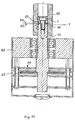
- the component to be connected is a disc 9 and the other a tubular element end piece 6; components can be fixed or a main axis "x" rotating.
- the connecting part 4 is operatively connected to the washer 9 and the working part 7 is operatively connected to the tubular element end piece 6.
- the connecting part 4 and the working part 7 each have a radial plane to the main axis "x", referred to as the separating gap plane "T", running connection surface 2 and counter surface 3.
- Shank screw 1 passes through the component 9 and the connecting part 4 and is screwed into the nut thread 8 in the working part 7, whereby it exerts a tensile stress on the latter two parts, which leads to an increased edge pressure of these parts within the tubular element end piece 6 and thus to a clamping effect leads.
- the component 9 and the tubular element end piece are connected to one another in a rotationally fixed manner by friction.
- the friction clutch shown in FIGS. 2 and 3 operates according to the same principle for the transmission of axial and rotational forces.
- a frictional force is generated in the tubular element end piece 6 due to edge pressure by the elements already described in detail above, the strength of which is adjustable.
- the tilt cam 10 is designed as a pin 11.
- a friction clutch can be formed between the drive shaft and the driven disk.
- a coupling part namely the clutch driven disk 17
- the friction being applied by the tensile force of an anchor screw 12, which has a shaft thread in the threaded bore 8 of the clutch driven pulley 17 is screwed in.
- the anchor screw 12 has a hollow bore 13, the tension anchor 21 runs, which is mounted by means of a ball head 22 in a concave-spherical recess 23 of the connecting part 4 under the pretension of a helical compression spring 24, and the connecting part 4 with the connecting surface 2 in the separating gap area against the counter surface 3 of the anchor screw 12, which is provided with the tilting cam 10.
- the compression spring 24 is embedded in a cylindrical annular groove 15 in the head of the anchor screw 12, an annular spring arranged on the tension anchor 21 serving as an abutment.
- the annular gap is designated by 5.
- the tension anchor 21 runs out into a threaded pin 26 with a nut 27 screwed onto it, against which a washer 28 bears as an abutment, which represents the abutment for the compression spring 24.
- the advantage of this embodiment compared to the design according to FIG. 4 is that the spring pressure and thus the frictional force of the tilting cam connection are set very finely and the slip effect can be metered as desired when it comes to transferring the force to a desired size limit.
- a further application according to FIGS. 6 and 7 enables a uniaxial socket connection of two straight pipe element end pieces.
- the socket piece 41 has the connection parts 4 at both ends with connection surfaces 2 running in the separating gap plane T and attached to them in the peripheral area Tilting cams 10.
- the tubular element end pieces 61 are plugged onto the connecting parts 4 on both sides, and these are in operative connection with the working parts 7 provided with the nut threads 8 and having the counter surfaces 3.
- the clamping connection is made with the socket piece 41, which is provided with the windows 42 for inserting and tightening the shaft screws 1.
- the target transmission torque can be set by metering the clamping force using the socket head screws.
- a screw thread connection is shown in different views or partial sections, which combines three tubular element end pieces 61, 62, 63 running in two planes in a knot-like manner.
- the three-axis socket piece is designated, which is provided with three connecting parts 4 and the windows 43 in order to enable access for the insertion of the socket head screws 1.
- These are screwed into the female thread 8 in the working parts 7, which are operatively connected to the pipe element end pieces 61, 62, 63 which are plugged onto the connecting parts 4 and are provided with tilting cams 10 which are supported on the connecting surfaces 2 in the separating gap levels T.
- a node connection modified from this can be seen from the illustrations in FIGS. 11 and 12.
- five pipe element end pieces 61 to 65 are combined in two planes in a star-shaped sleeve piece 45, which with five connecting parts 4 is equipped, on which the mentioned pipe element end pieces are attached.
- a clamping force is produced by the socket head screws 1, which are screwed into the nut thread 8 of the working parts 7, and which are in operative connection with the tubular element end pieces 61, 62, 63 .
- FIGS. 13, 14 and 15 are comparable with the knot connection according to FIGS. 8 to 10.
- it is a screw connection of three tubular element end pieces 66 and 67 which run in two planes but are square and which are connected to working parts 48 of the square socket piece 46 are attached.
- the shaft screws designated 1 and screwed into the nut thread 8 the clamping force is generated, by means of which the connecting parts 47 having the nut thread 8 are braced with the square socket piece 46, the tilting cams 10 in the separating gap planes T effecting the friction connection.
- 16 and 17 show applications of tilting cam connections on rotating devices, which are rotary encoders.
- 49 denotes the rotary encoder housing, 50 the drive shaft and 56 the encoder shaft, on which the indexing disk 55 is seated in the area of the scanning unit 58.
- acc. Fig. 16 is generated by means of the tension screw 60 inserted in a donor shaft hollow bore 57 by screwing into the nut thread 8 in the working part 7 provided with the Kippnok ken 10, the required clamping force to the KippnockenfriktionsMIS to produce with the working part 7, which is operatively connected to the drive shaft 50.
- the shaft screw 1 which is used to generate the clamping force and is provided in the tilting part 51 with the tilting cam 10, is screwed into the encoder shaft 54.
- the counter surface and the end face in the separation gap plane T are designated, in which the tilting cam friction connection is produced when the shaft screw 1 is tightened.
- the friction force can be metered by appropriately tightening the screw connection, and the connection can be easily released or separated at any time by loosening the screw connection.
Landscapes
- Engineering & Computer Science (AREA)
- General Engineering & Computer Science (AREA)
- Mechanical Engineering (AREA)
- Transmission Devices (AREA)
Applications Claiming Priority (2)
| Application Number | Priority Date | Filing Date | Title |
|---|---|---|---|
| DE4314864A DE4314864A1 (de) | 1993-05-05 | 1993-05-05 | Schraubgewindeverbindung |
| DE4314864 | 1993-05-05 |
Publications (1)
| Publication Number | Publication Date |
|---|---|
| EP0623755A1 true EP0623755A1 (fr) | 1994-11-09 |
Family
ID=6487243
Family Applications (1)
| Application Number | Title | Priority Date | Filing Date |
|---|---|---|---|
| EP94107066A Withdrawn EP0623755A1 (fr) | 1993-05-05 | 1994-05-05 | Connection à vis taraudée |
Country Status (2)
| Country | Link |
|---|---|
| EP (1) | EP0623755A1 (fr) |
| DE (1) | DE4314864A1 (fr) |
Cited By (6)
| Publication number | Priority date | Publication date | Assignee | Title |
|---|---|---|---|---|
| DE29506323U1 (de) * | 1995-04-12 | 1995-06-29 | Rosenkötter, Torsten, Dipl.-Kaufm., 22179 Hamburg | Knotenverbindung für Tragsysteme |
| EP1006035A1 (fr) * | 1998-12-02 | 2000-06-07 | Talbot GmbH & Co. KG | Connexion pour deux profilés légers |
| DE19936237A1 (de) * | 1999-08-05 | 2001-02-15 | Heidenhain Gmbh Dr Johannes | Drehgeber mit einer Klemmvorrichtung |
| EP3173000A1 (fr) * | 2014-12-03 | 2017-05-31 | Gebr. Willach GmbH | Porte en verre coulissante pour cabine de douche |
| CN114867946A (zh) * | 2019-12-16 | 2022-08-05 | 思瑞史密斯集团有限公司 | 一种锚固组件 |
| CN115979152A (zh) * | 2022-11-04 | 2023-04-18 | 珠海华粤传动科技有限公司 | 一种带防错功能的湿式离合器分离间隙检测方法 |
Citations (1)
| Publication number | Priority date | Publication date | Assignee | Title |
|---|---|---|---|---|
| CH266955A (de) * | 1947-06-05 | 1950-02-28 | Reuge & Cie | Feststellvorrichtung an einem aus teleskopartig ineinander verschiebbaren Teilen bestehenden Gegenstand. |
Family Cites Families (25)
| Publication number | Priority date | Publication date | Assignee | Title |
|---|---|---|---|---|
| US2409204A (en) * | 1945-08-18 | 1946-10-15 | James E Gall | Shaft locking device |
| FR1256016A (fr) * | 1960-02-02 | 1961-03-17 | Perfectionnements apportés aux dispositifs d'assemblage et leurs applications | |
| DE1817398B2 (de) * | 1968-02-22 | 1972-02-24 | Fouquet Werk Frauz & Planck, 7407 Rottenburg | Zylinderspannwerkzeug mit elastischen z foermigen spannelemen ten |
| FR2080328A5 (fr) * | 1970-02-17 | 1971-11-12 | Aleurope | |
| SE366366B (fr) * | 1972-04-14 | 1974-04-22 | Byggstaempf E B Ind Ab | |
| DE2413707B2 (de) * | 1974-03-21 | 1977-09-08 | Siemens AG, 1000 Berlin und 8000 München | Verbindungselement fuer hohlprofilteile, insbesondere eckverbinder |
| DE2448239C3 (de) * | 1974-10-09 | 1979-10-11 | Georg Prof. 7743 Furtwangen Seewang | Justiervorrichtung für einen Absolutwinkelschrittgeber |
| FR2298720A1 (fr) * | 1975-01-27 | 1976-08-20 | Chamayou Gerard | Noeuds d'assemblage pour structures multidirectionnelles et structures comportant de tels noeuds |
| US4113395A (en) * | 1975-05-01 | 1978-09-12 | Wald Manufacturing Company, Inc. | Bicycle stem and fork tube assembly |
| US4214795A (en) * | 1977-11-25 | 1980-07-29 | Shoketsu Kinzoku Kogyo Kabushiki Kaisha | Piston braking device for hydraulic or pneumatic cylinders |
| DE3017193A1 (de) * | 1980-05-05 | 1981-11-12 | Siemens AG, 1000 Berlin und 8000 München | Einbauarmatur fuer messwertaufnehmer an schwer zugaenglich messstellen in maschinen |
| EP0086314A1 (fr) * | 1982-02-15 | 1983-08-24 | APPLICATIONS MECANIQUES ET ROBINETTERIE INDUSTRIELLE A.M.R.I. Société anonyme dite: | Dispositif de serrage, à déplacement de faible amplitude, d'un élément tel qu'un joint d'étanchéité |
| DE3432074A1 (de) * | 1983-09-09 | 1985-03-28 | O & K Orenstein & Koppel Ag, 1000 Berlin | Verfahren und einrichtung zum festen verbinden und wiederloesen benachbarter endglieder einer grenzleistungstraktionskette |
| FR2566483B1 (fr) * | 1984-06-21 | 1991-10-04 | Cuilleron J | Ecrou a double effet permettant le reglage et le rattrapage des jeux dans les assemblages mecaniques filetes |
| DE3427709C1 (de) * | 1984-07-27 | 1989-11-02 | Max Stegmann GmbH, Uhren- und Elektroapparatefabrik, 7710 Donaueschingen | Justiervorrichtung fuer Winkelschrittgeber |
| CH665456A5 (de) * | 1984-11-23 | 1988-05-13 | Fehlbaum & Co | Eckverbinder fuer rohrgestelle. |
| DE3537235A1 (de) * | 1985-10-19 | 1987-04-23 | Stegmann Uhren Elektro | Justiervorrichtung fuer winkelschrittgeber |
| DE3642230C2 (de) * | 1986-12-10 | 1995-09-21 | Heidenhain Gmbh Dr Johannes | Inkrementaler oder absoluter Drehgeber mit einer Klemmvorrichtung |
| GB2205141B (en) * | 1987-05-12 | 1991-07-24 | Yau King Choy | Securing connector for tubes |
| GB8711753D0 (en) * | 1987-05-19 | 1987-06-24 | Skf Uk Ltd | Torque transmitting assembly |
| DE8713664U1 (de) * | 1987-10-12 | 1987-11-19 | Max Stegmann GmbH, Uhren- und Elektroapparatefabrik, 78166 Donaueschingen | Drehgeber |
| DE3744295A1 (de) * | 1987-12-28 | 1989-07-13 | Kontec Gmbh | Klemmvorrichtung zum festklemmen einer linear beweglichen stange |
| US5010708A (en) * | 1989-03-10 | 1991-04-30 | Anderson Corporation | Corner lock |
| DE4131903C2 (de) * | 1991-09-25 | 1994-09-15 | Hans Josef Kitz | Vorrichtung zum Parallelverbinden von zwei Konstruktionsprofilen |
| DE4204606A1 (de) * | 1992-02-15 | 1993-08-19 | Roland Man Druckmasch | Kraftschluessige verbindung fuer maschinenteile |
-
1993
- 1993-05-05 DE DE4314864A patent/DE4314864A1/de not_active Withdrawn
-
1994
- 1994-05-05 EP EP94107066A patent/EP0623755A1/fr not_active Withdrawn
Patent Citations (1)
| Publication number | Priority date | Publication date | Assignee | Title |
|---|---|---|---|---|
| CH266955A (de) * | 1947-06-05 | 1950-02-28 | Reuge & Cie | Feststellvorrichtung an einem aus teleskopartig ineinander verschiebbaren Teilen bestehenden Gegenstand. |
Cited By (9)
| Publication number | Priority date | Publication date | Assignee | Title |
|---|---|---|---|---|
| DE29506323U1 (de) * | 1995-04-12 | 1995-06-29 | Rosenkötter, Torsten, Dipl.-Kaufm., 22179 Hamburg | Knotenverbindung für Tragsysteme |
| EP1006035A1 (fr) * | 1998-12-02 | 2000-06-07 | Talbot GmbH & Co. KG | Connexion pour deux profilés légers |
| DE19936237A1 (de) * | 1999-08-05 | 2001-02-15 | Heidenhain Gmbh Dr Johannes | Drehgeber mit einer Klemmvorrichtung |
| EP3173000A1 (fr) * | 2014-12-03 | 2017-05-31 | Gebr. Willach GmbH | Porte en verre coulissante pour cabine de douche |
| EP3195773A1 (fr) * | 2014-12-03 | 2017-07-26 | Gebr. Willach GmbH | Porte coulissante en verre |
| CN114867946A (zh) * | 2019-12-16 | 2022-08-05 | 思瑞史密斯集团有限公司 | 一种锚固组件 |
| CN114867946B (zh) * | 2019-12-16 | 2024-03-08 | 思瑞史密斯集团有限公司 | 一种锚固组件 |
| CN115979152A (zh) * | 2022-11-04 | 2023-04-18 | 珠海华粤传动科技有限公司 | 一种带防错功能的湿式离合器分离间隙检测方法 |
| CN115979152B (zh) * | 2022-11-04 | 2025-10-14 | 珠海华粤传动科技有限公司 | 一种带防错功能的湿式离合器分离间隙检测方法 |
Also Published As
| Publication number | Publication date |
|---|---|
| DE4314864A1 (de) | 1994-11-10 |
Similar Documents
| Publication | Publication Date | Title |
|---|---|---|
| EP0732081B1 (fr) | Elément d'ancrage | |
| DE19513794A1 (de) | Selbsthaltendes Verbindungselement | |
| EP2208576A2 (fr) | Commande par oscillation | |
| DE69302685T2 (de) | Schwenkverbindungsglied | |
| DE102015109278B4 (de) | Verbindungssystem, Klemmschraube, Verfahren zum Verbinden zweier Bauteile | |
| EP0713018B1 (fr) | Dispositif de fixation | |
| DE102019118338B4 (de) | Drehmoment-Antriebskopf | |
| DE102021100041B4 (de) | Drehmomentschlüssel, mit dem die Genauigkeit des Drehmomentwerts aufrechterhalten werden kann | |
| EP1588975B1 (fr) | Attelage | |
| DE69734684T2 (de) | Feinmechanische querpositionierungsvorrichtung | |
| DE102013000624A1 (de) | Mutter zum Befestigen von Komponenten an einem profilierten Element über Schraubmittel und Verfahren zu deren Montage | |
| DE4210488A1 (de) | Verbindungseinrichtung für ein insbesondere rohrförmiges Bauteil | |
| EP0623755A1 (fr) | Connection à vis taraudée | |
| DE2708538A1 (de) | Verbindung zwischen den kettengliedern einer gleiskette | |
| DE3219520C2 (fr) | ||
| DE2655728C2 (de) | Lösbare Naben-Wellenverbindung | |
| DE60319855T2 (de) | Rotierbare verbindung | |
| DE102022107259B3 (de) | Drehlager für ein Deckenstativ | |
| EP0568106A1 (fr) | Filetape autobloquant | |
| EP0470470A2 (fr) | Cheville avec un manchon à cheville | |
| DE2620996A1 (de) | Verriegelungsmutter | |
| DE20302843U1 (de) | Arretierungseinheit zur Sicherung einer Wellenmutter auf einem Wellengewinde | |
| EP1316737B1 (fr) | Anneau de serrage | |
| DE19604665A1 (de) | Querverbinder für Profilstäbe | |
| DE20111793U1 (de) | Muffenverbindung für Betonstäbe |
Legal Events
| Date | Code | Title | Description |
|---|---|---|---|
| PUAI | Public reference made under article 153(3) epc to a published international application that has entered the european phase |
Free format text: ORIGINAL CODE: 0009012 |
|
| AK | Designated contracting states |
Kind code of ref document: A1 Designated state(s): AT CH DE FR IT LI |
|
| 17P | Request for examination filed |
Effective date: 19950506 |
|
| 17Q | First examination report despatched |
Effective date: 19960820 |
|
| STAA | Information on the status of an ep patent application or granted ep patent |
Free format text: STATUS: THE APPLICATION IS DEEMED TO BE WITHDRAWN |
|
| 18D | Application deemed to be withdrawn |
Effective date: 19970402 |