EP0624042B1 - Fernsehsignal welches kompatibel ist mit einem Standardfernsehsignal, Verfahren zur Übertragung dieses Fernsehsignals und Vorrichtung zur Verarbeitung des Fernsehsignals - Google Patents
Fernsehsignal welches kompatibel ist mit einem Standardfernsehsignal, Verfahren zur Übertragung dieses Fernsehsignals und Vorrichtung zur Verarbeitung des Fernsehsignals Download PDFInfo
- Publication number
- EP0624042B1 EP0624042B1 EP93107461A EP93107461A EP0624042B1 EP 0624042 B1 EP0624042 B1 EP 0624042B1 EP 93107461 A EP93107461 A EP 93107461A EP 93107461 A EP93107461 A EP 93107461A EP 0624042 B1 EP0624042 B1 EP 0624042B1
- Authority
- EP
- European Patent Office
- Prior art keywords
- signal
- signal processing
- component
- additional control
- additional
- Prior art date
- Legal status (The legal status is an assumption and is not a legal conclusion. Google has not performed a legal analysis and makes no representation as to the accuracy of the status listed.)
- Expired - Lifetime
Links
Images


Classifications
-
- H—ELECTRICITY
- H04—ELECTRIC COMMUNICATION TECHNIQUE
- H04N—PICTORIAL COMMUNICATION, e.g. TELEVISION
- H04N7/00—Television systems
- H04N7/01—Conversion of standards, e.g. involving analogue television standards or digital television standards processed at pixel level
- H04N7/0117—Conversion of standards, e.g. involving analogue television standards or digital television standards processed at pixel level involving conversion of the spatial resolution of the incoming video signal
- H04N7/0122—Conversion of standards, e.g. involving analogue television standards or digital television standards processed at pixel level involving conversion of the spatial resolution of the incoming video signal the input and the output signals having different aspect ratios
-
- H—ELECTRICITY
- H04—ELECTRIC COMMUNICATION TECHNIQUE
- H04N—PICTORIAL COMMUNICATION, e.g. TELEVISION
- H04N9/00—Details of colour television systems
- H04N9/64—Circuits for processing colour signals
-
- H—ELECTRICITY
- H04—ELECTRIC COMMUNICATION TECHNIQUE
- H04N—PICTORIAL COMMUNICATION, e.g. TELEVISION
- H04N11/00—Colour television systems
- H04N11/06—Transmission systems characterised by the manner in which the individual colour picture signal components are combined
- H04N11/12—Transmission systems characterised by the manner in which the individual colour picture signal components are combined using simultaneous signals only
- H04N11/14—Transmission systems characterised by the manner in which the individual colour picture signal components are combined using simultaneous signals only in which one signal, modulated in phase and amplitude, conveys colour information and a second signal conveys brightness information, e.g. NTSC-system
- H04N11/16—Transmission systems characterised by the manner in which the individual colour picture signal components are combined using simultaneous signals only in which one signal, modulated in phase and amplitude, conveys colour information and a second signal conveys brightness information, e.g. NTSC-system the chrominance signal alternating in phase, e.g. PAL-system
-
- H—ELECTRICITY
- H04—ELECTRIC COMMUNICATION TECHNIQUE
- H04N—PICTORIAL COMMUNICATION, e.g. TELEVISION
- H04N11/00—Colour television systems
- H04N11/06—Transmission systems characterised by the manner in which the individual colour picture signal components are combined
- H04N11/12—Transmission systems characterised by the manner in which the individual colour picture signal components are combined using simultaneous signals only
- H04N11/14—Transmission systems characterised by the manner in which the individual colour picture signal components are combined using simultaneous signals only in which one signal, modulated in phase and amplitude, conveys colour information and a second signal conveys brightness information, e.g. NTSC-system
- H04N11/16—Transmission systems characterised by the manner in which the individual colour picture signal components are combined using simultaneous signals only in which one signal, modulated in phase and amplitude, conveys colour information and a second signal conveys brightness information, e.g. NTSC-system the chrominance signal alternating in phase, e.g. PAL-system
- H04N11/167—Transmission systems characterised by the manner in which the individual colour picture signal components are combined using simultaneous signals only in which one signal, modulated in phase and amplitude, conveys colour information and a second signal conveys brightness information, e.g. NTSC-system the chrominance signal alternating in phase, e.g. PAL-system a resolution-increasing signal being multiplexed to the PAL-system signal, e.g. PAL-PLUS-system
-
- H—ELECTRICITY
- H04—ELECTRIC COMMUNICATION TECHNIQUE
- H04N—PICTORIAL COMMUNICATION, e.g. TELEVISION
- H04N5/00—Details of television systems
- H04N5/76—Television signal recording
- H04N5/765—Interface circuits between an apparatus for recording and another apparatus
-
- H—ELECTRICITY
- H04—ELECTRIC COMMUNICATION TECHNIQUE
- H04N—PICTORIAL COMMUNICATION, e.g. TELEVISION
- H04N7/00—Television systems
- H04N7/007—Systems with supplementary picture signal insertion during a portion of the active part of a television signal, e.g. during top and bottom lines in a HDTV letter-box system
-
- H—ELECTRICITY
- H04—ELECTRIC COMMUNICATION TECHNIQUE
- H04N—PICTORIAL COMMUNICATION, e.g. TELEVISION
- H04N7/00—Television systems
- H04N7/08—Systems for the simultaneous or sequential transmission of more than one television signal, e.g. additional information signals, the signals occupying wholly or partially the same frequency band, e.g. by time division
-
- H—ELECTRICITY
- H04—ELECTRIC COMMUNICATION TECHNIQUE
- H04N—PICTORIAL COMMUNICATION, e.g. TELEVISION
- H04N7/00—Television systems
- H04N7/08—Systems for the simultaneous or sequential transmission of more than one television signal, e.g. additional information signals, the signals occupying wholly or partially the same frequency band, e.g. by time division
- H04N7/087—Systems for the simultaneous or sequential transmission of more than one television signal, e.g. additional information signals, the signals occupying wholly or partially the same frequency band, e.g. by time division with signal insertion during the vertical blanking interval only
- H04N7/088—Systems for the simultaneous or sequential transmission of more than one television signal, e.g. additional information signals, the signals occupying wholly or partially the same frequency band, e.g. by time division with signal insertion during the vertical blanking interval only the inserted signal being digital
- H04N7/0882—Systems for the simultaneous or sequential transmission of more than one television signal, e.g. additional information signals, the signals occupying wholly or partially the same frequency band, e.g. by time division with signal insertion during the vertical blanking interval only the inserted signal being digital for the transmission of character code signals, e.g. for teletext
-
- H—ELECTRICITY
- H04—ELECTRIC COMMUNICATION TECHNIQUE
- H04N—PICTORIAL COMMUNICATION, e.g. TELEVISION
- H04N9/00—Details of colour television systems
- H04N9/64—Circuits for processing colour signals
- H04N9/641—Multi-purpose receivers, e.g. for auxiliary information
-
- H—ELECTRICITY
- H04—ELECTRIC COMMUNICATION TECHNIQUE
- H04N—PICTORIAL COMMUNICATION, e.g. TELEVISION
- H04N9/00—Details of colour television systems
- H04N9/79—Processing of colour television signals in connection with recording
- H04N9/80—Transformation of the television signal for recording, e.g. modulation, frequency changing; Inverse transformation for playback
- H04N9/82—Transformation of the television signal for recording, e.g. modulation, frequency changing; Inverse transformation for playback the individual colour picture signal components being recorded simultaneously only
- H04N9/83—Transformation of the television signal for recording, e.g. modulation, frequency changing; Inverse transformation for playback the individual colour picture signal components being recorded simultaneously only the recorded chrominance signal occupying a frequency band under the frequency band of the recorded brightness signal
-
- H—ELECTRICITY
- H04—ELECTRIC COMMUNICATION TECHNIQUE
- H04N—PICTORIAL COMMUNICATION, e.g. TELEVISION
- H04N9/00—Details of colour television systems
- H04N9/79—Processing of colour television signals in connection with recording
- H04N9/80—Transformation of the television signal for recording, e.g. modulation, frequency changing; Inverse transformation for playback
- H04N9/82—Transformation of the television signal for recording, e.g. modulation, frequency changing; Inverse transformation for playback the individual colour picture signal components being recorded simultaneously only
- H04N9/83—Transformation of the television signal for recording, e.g. modulation, frequency changing; Inverse transformation for playback the individual colour picture signal components being recorded simultaneously only the recorded chrominance signal occupying a frequency band under the frequency band of the recorded brightness signal
- H04N9/832—Transformation of the television signal for recording, e.g. modulation, frequency changing; Inverse transformation for playback the individual colour picture signal components being recorded simultaneously only the recorded chrominance signal occupying a frequency band under the frequency band of the recorded brightness signal using an increased bandwidth for the luminance or the chrominance signal
Definitions
- the invention relates to an improvement of a television signal of a new standard, which includes a first signal component representing a picture having usual vertical resolution of a conventional television standard such as, for instance, PAL standard, which signal can be reproduced by a television receiver for the conventional standard, a second signal component to be utilized in video equipments for the new television standard such as video cassette recorders or television receivers so as to improve the vertical resolution of the picture recorded or reproduced thereby, and an information data signal for controlling video equipments for the conventional or new television standard.
- the invention further relates to a method of transmitting such the improved new standard television signal and to a video equipment for processing the improved new standard television signal.
- a picture signal representing a studio picture source of a wide aspect ratio 16:9 having the active 575 lines per frame is separated by vertical filtering to perform a line down conversion of 3/4 into a first picture component signal (luminance and chrominance) providing a usual vertical resolution of a picture which is displayed in a letter box size by 430 lines in a television screen of a normal aspect ratio 4:3 and by vertical filtering to perform a line down conversion of 1/4 into a second picture component signal (luminance only) improving a vertical resolution of a picture which is displayed in a full size by 575 lines in a television screen of the wide aspect ratio according to the first picture component signal.
- first picture component signal luminance and chrominance
- the first picture component signal is coded according to the PAL standard and transmitted during 430 active line periods in the middle of each frame of a television signal of total 625 lines and the second picture component signal, so called "helper signal" is subjected to a carrier suppressed side band amplitude modulation of one of the color sub-carrier signals, preferably the sub-carrier signal having a constant signal phase for the color difference signal U, and transmitted at the black level during the remaining upper 72 and lower 72 line periods of the each frame.
- a conventional PAL standard television receiver (hereinafter PAL-TV receiver) of the normal aspect ratio can display a picture in a letter-box size represented by the first picture component signal during the middle 430 lines on the screen.
- the helper signal transmitted in the upper 72 and lower 72 line periods can be seen in principle as black panels adjacent the picture.
- a conventional PAL standard television receiver having the wide aspect ratio or a tailored PAL PLUS system television receiver (hereinafter PAL PLUS-TV receiver) having the wide aspect ratio can display a picture represented by the first picture component signal in a full size on the screen by means of zooming processing by increasing the vertical deflection amplitude.
- the vertical resolution of this picture is same as that of the above picture in the letter box size.
- the helper signal is demodulated, subjected to a line up conversion of 4/1, and combined with the first picture component signal subjected to a line conversion of 4/3 so that a higher resolution picture of the wide aspect ratio can be displayed in the active 575 lines.
- the information data signal is transmitted in a certain format during the line 23 of the PAL PLUS system television signal (hereinafter PAL PLUS-TV signal).
- PAL PLUS-TV signal the lines 7 to 22 of each field are already assigned for teletext or VITS data.
- the information data signal may contain information of the aspect ratio of the pitcure transmitted, transmission of the helper signal, encoding of the color plus, and so on, which are not presently transmitted in the PAL standard television signal (hereinafter PAL-TV signal).
- PAL-TV signal PAL standard television signal
- the PAL PLUS-TV signal is likely recorded by a current video signal recorder such as a video cassette recorder designed for the PAL standard (hereinafter current VCR).
- current VCR video cassette recorder designed for the PAL standard
- the PAL PLUS-TV signal including the information data signal is supplied to the current VCR which itself as a matter of course has not taken account of the PAL PLUS-TV signal and has no function to distinguish the PAL PLUS-TV signal from the PAL-TV signal
- the PAL PLUS-TV signal is recorded within the extent of the specification of PAL-TV signal and the same reproduced is forwarded to the PAL PLUS-TV receiver.
- the PAL PLUS-TV signal reproduced from the current VCR is, therefore, much transformed or distorted due to the recordable frequency band, unstable time base, and signal processing such as line comb filtering of the current VCR so as not to be correctly reproduced in the PAL PLUS-TV receiver anymore to fulfill the specification of the PAL PLUS system. Accordingly, the reproduced picture quality becomes deteriorated even in comparison with that reproduced as the PAL-TV signal.
- Document DE-A-4 000 790 discloses a colour video signal processor to be used in a PAL-VCR that adds an additional detection signal to the signal to be recorded, the additional detection signal having a predetermined phase depending on one of two modi of the luminance signal included in the signal to be recorded, to be able to correctly process the recorded luminance signal after reproduction according to the phase of the additional detection signal.
- this problem is solved by providing the new standard television signal such as, for example, the PAL PLUS-TV signal with an additional signal, by means of which it can be detected that the new standard television signal supplied to a video equipment for the new standard through an improper transmission medium is not suitable to be processed as the new standard television signal.
- the new standard television signal such as, for example, the PAL PLUS-TV signal
- an additional signal by means of which it can be detected that the new standard television signal supplied to a video equipment for the new standard through an improper transmission medium is not suitable to be processed as the new standard television signal.
- Claims 1 and 2 specify the signal in accordance with the invention
- claims 9 and 10 specify a method for transmitting said signal
- claims 17 and 18 specify equipment for processing said signal.
- the luminance signal is separated from the composite baseband video signal supplied to the input terminal 1 by the low pass filter 2 and frequency modulated by the frequency modulator 4 after subjected to a pre-emphasis by the pre-emphasis circuit 3.
- the frequency modulated luminance signal is limited its frequency band by the high pass filter 5 so as not to overlap the chrominance signal which frequency band is down-converted as described below and supplied to the couple of rotary recording video heads 7 through a recording amplifier 6.
- the chrominance signal is separated from the composite baseband video signal and limited its frequency band by the band-pass filter 8 and down-converted to a frequency band lower than the frequency band of the frequency modulated luminance signal by the down-converter 9 so that its carrier frequency equal 40 times the horizontal scanning frequency.
- the down-convetered chrominance signal is again limited its frequency band by the low-pass filter 10 and supplied to the couple of rotary recording video heads 7 together with the above frequency modulated luminance signal through the recording amplifier 6.
- the PLL (Phase Locked Loop) circuit 12 derives a first oscillating signal of 40 times the horizontal scanning frequency and synchronized with the horizontal synchronizing signal.
- the first oscillating signal is supplied to the phase shifter 13, which is controlled by the horizontal synchronizing signal and the vertical synchronizing signal in such manner that the oscillating signal from the PLL circuit 12 is subjected to phase shift so as to be phase-retarded by 90 degree at every horizontal synchronizing interval only in odd (even) fields or fields A and to remain at 0 degree in its phase in even (odd) fields or fields B.
- Such phase shifted first oscillating signal is supplied to the frequency converter 14 where the second oscillating signal from the local oscillator 15 is supplied.
- the third oscillating signal from the frequency converter 14 is supplied to the down-converter 9. Accordingly, the down-converted chrominance signal shall be phase-retarded by 90 degree at every horizontal synchronizing interval only in odd (even) fields or fields A and remain at 0 degree in its phase in even (odd) fields or fields B as shown in Fig. 2.
- the couple of the rotary recording video heads 7 which have a relative azimuth angle of 12 degree to each other, for instance, are rotated in accordance with the drum servo circuit 16 synchronizing with the vertical synchronizing signal so that signal of fields A and B is alternately recorded in the sequential slant tracks A and B adjacent to each other without guardbands as shown in Fig. 2.
- the couple of the rotary reproducing video heads 17 which have same azimuth angle as the couple of rotary recording video heads 7 are rotated in accordance with the drum servo circuit 18 so that the recorded video signal of fields A and B is reproduced from the sequential slant tracks A and B alternately.
- the frequency modulated luminance signal is separated from the reproduced video signal by the high-pass filter 19 and supplied to the frequency demodulator 20.
- the demodulated luminance signal is subjected to de-emphasis by the de-emphasis circuit 21 and derived to the output terminal 22.
- the down-converted chrominance signal is separated from the reproduced video signal by the low-pass filter 23 and up-converted to the frequency band higher than the frequency band of the demodulated luminance signal by the up-converter 24.
- the up-converted chrominance signal is supplied to the line comb filter 25 which consists of the delay line 26 having a delay time of 2 horizontal period and the adder 27.
- the output from the line comb filter 25 is derived to the output terminal 22 together with the luminance signal as a composite baseband video signal.
- the PLL circuit 29 derives a fourth oscillating signal of 40 times the horizontal scanning frequency in accordance with a fifth oscillating signal from the local oscillator 30.
- the fourth oscillating signal is supplied to the phase shifter 31, which is controlled by the horizontal synchronizing signal and the vertical synchronizing signal in such manner that the fourth oscillating signal from the PLL circuit 29 is subjected to phase shift so as to be phase-advanced by 90 degree at every horizontal synchronizing interval only in fields A and to remain at 0 degree in its phase in fields B.
- Such phase shifted fourth oscillating signal is supplied to the frequency converter 32 where the fifth oscillating signal from the local oscillator 30 is supplied.
- the sixth oscillating signal from the frequency converter 32 is supplied to the up-converter 24. Accordingly, the up-converted chrominance signal recovers the same constant phase as the chrominance signal before down-converted in the recording side.
- the cross-talk component of the luminance signal from the adjacent track is sufficiently reduced. Because such azimuth angle is, however, only effective to signal of high frequency band, there is a cross-talk of the chromlnance signal from the preceding and succeeding adjacent tracks. Such cross-talk component of the chrominance signal is effectively cancelled by means of the line comb filter 25.
- the cross-talk component of the chrominance signal reproduced from the adjacent tracks shall be phase-advanced by 90 degree at every horizontal synchronizing interval in fields B during reproducing fields A and remain as phase-retarded by 90 degree at every horizontal synchronizing interval in fields A during reproducing fields B as shown in Fig. 4.
- the chrominance signal derived from the adder 27 includes in principle only the chrominance signal reproduced from the desired field in a doubled amplitude and the cross-talk component from the adjacent tracks is cancelled. This cross-talk cancelling processing described above is performed, provided that there is line correlation between the two chrominance signals from two lines. Therefore, if there is no or less line correlation between two signals, the output signal from the line comb filter 25 is distorted.
- the modulated helper signal in the PAL PLUS-TV signal is modulated by color sub-carrier as described in the introductory part of the specification, the modulated helper signal is recorded by the current VCR as the down-cnverted chrominance signal. Therefore, the modulated helper signal is filtered by the low-pass filter 23 and supplied to the line comb filter 25 in the reproducing side. Because the helper signal, however, is generated by vertical filtering which performs a down-conversion of the luminance signal from 575 lines to 144 lines, the modulated helper signals undelayed and delayed by the delay line 26 have no or less line correlation.
- the modulated helper signal which is subjected to such cross-talk cancel processing by means of the line comb filter 25 is demodulated and utilized to improve the vertical resolution of the picture in the PAL PLUS-TV receiver, the total picture quality becomes deteriorated than the picture quality reproduced as the PAL-TV signal. Accordingly, it is necessary to detect that the helper signal has been subjected to such signal processing deteriorating the picture quality.
- the PAL PLUS-TV signal is improved by adding such an additional signal as to make it possible to detect whether the input video signal supplied to a video equipment for the PAL PLUS-TV signal such as the PAL PLUS-TV receiver is subjected to signal processing improper to be handle as the PAL PLUS-TV signal.
- the output of the line comb filter 25 has normally a double of the amplitude of the chrominance signal or the color burst supplied to the line comb filter 25 due to the addition in the adder 27, provided that the signal phase of two signals supplied to the adder 27 is identical. Therefore, if an additional signal having a certain frequency band is inserted in a certain location of a certain line of the PAL PLUS-TV signal and if no signal component having the similar frequency band is located in the same location of another line separated from the certain line by two lines, the output having a half of the usual amplitude is obtained from the line comb filter 25 at the timing of the reproduction in the certain location of the certain line or the another line. If such abnormal condition can be generated intentionally, it can be used for detection of the signal processing deteriorating the picture quality.
- the chrominance signal is normally always included during the active 575 lines of each frame (from the second half of line 23 to line 310 and from line 336 to the first half of line 623 in respective fields) in the PAL-TV signal. Additionally, the color burst is constantly inserted in the back porch of the horizontal synchronizing signal except the vertical blanking period. Therefore, if such an additional signal has a frequency band near the frequency band of the chrominance signal or the color burst, other than the active lines of the PAL PLUS-TV signal is advisable as the location to be inserted the additional signal. It is, however, also possible in principle that any of the active 575 lines can be reserved for the additional signal according to circumstances.
- the line 23 is allocated for the information data signal as described in the introductory part of the specification. It is proposed as an example of such information data that a preamble of 16 time slot as a run-in code and a start code having a pulse sequence of, for instance, "1101010111101001", an aspect ratio code of 3 bits occupying 6 time slot, a subtitle code of 1 bit occupying 2 time slot, a first reserved area occupying 8 time slot, a PAL PLUS code of 1 bit occupying 2 time slot, a film mode code of 1 bit occupying 2 time slot, a color plus code of 1 bit occupying 2 time slot, a helper code of 2 bit occupying 4 time slot, a second reserved area occupying 6 time slot, and a third reserved area occupying 8 time slot are transmitted in this sequense in the line 23 as shown in Fig.
- This pattern signal having the frequency 4.5 MHz is very close to the color burst of the frequency 4.43 MHz.
- the line 21 may be occupied by teletext data, because the latter has a frequency band up to 3.47 MHz in the composite baseband video signal, its signal component is treated as the luminance signal in the VCR. Therefore, if the output signals regarding the lines 21 and 23 from the low-pass filter 23 are supplied to the line comb filter 25 through the up-converter 24, the output having the desired half amplitude is obtained from the line comb filter 25 at the time when the HF code is directly supplied to the adder 27 by-passing the delay line 26 regardless of the phase of the HF code.
- the location where the HF code is inserted is not limited to the first half of the line 23 nor a specific position within a line as exemplified above.
- the helper signal commences from the line 24 in the PAL PLUS system.
- the HF code can be modified to other coded data, bi-phase coded data for example, or signal having basically a frequeny band around 4.5 MHz, preferably within the range of 4 to 5 MHz. In this case, any other information data as the source code can be transmitted on the coded data.
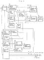
- a PAL PLUS signal processing part in the video equipment according to the invention will be explained, though the only important part is described and the other detail part will be omitted to simplify the explanation.
- the composite baseband video signal according to the PAL PLUS system is supplied to the demultiplexer 34 through the input terminal 33 so as to be separated into the signal of the middle 430 lines and the modulated helper signal in the upper 72 and lower 72 lines.
- the signal of the middle 430 lines are supplied to the color plus decoder 35 where the luminace signal Y' and color difference signals U' and V' are obtained in the reverse manner of the encoder as descirbed in the article "Eintechnisch Kunststoff Kunststoff togetheren PAL-Codtechnik und -Decodtechnik” by R. Kays, FERNSEH- UND KINO-TECHNIK, 44 Canalgang Nr. 11/1990, and further supplied to the up-conversion matrix 36 and the up-converter 37 through the switching circuits S1, S2 and S3, respectively.
- the signal of the middle 430 lines are also supplied to the line comb filter 38 so as to be separated into the luminace signal Y'' and the chrominance signal C'' which is further supplied to the PAL color decoder 39 where the color difference signals U'' and V'' are derived.
- the luminace signal Y'' from the line comb filter 38 and the color difference signals U'' and V'' from the PAL color decoder 39 are further supplied to the up-conversion matrix 36 and the up-converter 37 through the switching circuits S1, S2 and S3, respectively.
- the modulated helper signal in the upper 72 and lower 72 lines is demodulated in the helper signal demodulator 40 and the demodulated helper signal Y''' is further supplied to the up-coversion matrix 36 through the switching circuit S4.
- the demodulated helper signal Y''' of the upper 72 and lower 72 are combined with the luminance signal Y' or Y'' of the middle 430 lines in the up-conversion matrix 36 so as to be up-converted into the luminance signal Y of 575 lines with an improved vertical resolution, while the color difference signals U' or U'' and V' or V'' of the middle 430 lines are also up-converted into the color difference signals U and V of 575 lines.
- the up-converted luminance signal Y and color difference signals U and V can be further converted into the color component signals R, G and B in the Y/U/V-R/G/B matrix 41, if necessary.
- the motion detector 42 is provided to receive the composite baseband video signal and detect the motion in the picture represented by the video signal.
- the detection signal is supplied through the AND circuit 43 to the switching circuits S1, S2 and S3, which are changed over from the contacts B to the contacts A, respectively, if no or little motion in the picture is detected, so that the luminance signal Y' and the color difference signals U' and V' from the color plus decoder 35 are supplied to the up-conversion matrix 36 and the up-converter 37, respectively, and which are changed over from the contacts A to the contacts B, respectively, if large motion in the picture is detected, so that the luminance signal Y'' from the line comb filter 38 and the color difference signals U'' and V'' from the PAL color decoder 39 are supplied to the up-conversion matrix 36 and the up-converter 37, respectively.
- delay circuits for delay compensation should be inserted in the passes for example between the helper signal demodulator 40 and the up-conversion matrix 36, the line comb filter 38 and the up-conversion matrix 36, the PAL color decoder 39 and the up-converter 37, if necessary, though it is not illustrated.
- the embodiment includes the synchronizing signal separator 44, the timing signal generator 45, the PLL (Phase Locked Loop) oscillator 46, the color burst detector 47, the data extractor 48, the burst level detect and hold circuit 49, the HF code level detect and hold circuit 50 and the level comparator 51.
- the PLL Phase Locked Loop
- the vertical and horizontal synchronizing signals are separeted in the synchronizing signal separator 44 from the composite baseband video signal supplied to the input terminal 33 so as to be supplied to the timing signal generator 45.
- the timing signals generated in the timing signal generator 45 are supplied to respectve circuits wherever needed.
- the PLL (Phase Locked Loop) oscillator 46 generates the oscillating signal having the frequency of 4.43 MHz, which is supplied to the PAL color decoder 41 and the color plus decoder 35, which also includes a PAL color decoder, as well as the color burst detector 47 and the data extractor 48.
- the color burst signal which is transmitted at the back porch of every line as shown in Fig. 5 is tuned to the oscillating signal from the PLL oscillator 46 and extracted by the color burst detector 47 at the timing of the back porch according to a proper timing signal from the timing signal generator 45.
- the data extractor 48 derives the HF code, color plus code, helper code, aspect ratio code, film mode code and so on at the respective timing as described above according to respective proper timing signals from the timing signal generator 45.
- the HF code may be detected in the data extractor 48 to be tuned to the oscillating signal from the PLL oscillator 46.
- the color plus code is supplied through the switching circuit S5 to the AND circuit 43, so that if the color plus code indicating that the television signal subjected to the color plus encoding is transmitted, the above descibed color plus decoding is performed according to the detection signal from the motion detector 42.
- the helper signal bit is supplied through the switching circuit S6 to the switching circuit S4 so that the helper signal becomes available, if the helper code indicating that the helper signal is transmitted.
- the color burst signal and the HF code signal are supplied to the burst level detect and hold circuit 49 and the HF code level detect and hold circuit 50, respectively, in which its signal levels are detected and maintained, respectively.
- the level signals from the burst level detect and hold circuit 49 and the HF code level detect and hold circuit 50 are supplied to the level comparator 51, respectively, so as to be compared with each other its levels at a proper timing according to a timing signal from the timing signal generator 45.
- each levels are normalized, because the color burst signal and the HF code may be transmitted in different levels, respectively.
- the normalized level of the HF code signal is about half of or less than the normalized level of the color burst signal, whereby the level comparator 51 provides the switching circuits S5 and S6 with the switch-OFF signals.
- the detection signal from the motion detector 42 becomes invalid so that the switching circuits S1, S2 and S3 are changed over from the contacts A to the contacts B to always supply the up-conversion matrix 36 and the up-converter 37 with the luminance signal Y'' from the line comb filter 38 and the color difference signals U'' and V'' from the PAL color decoder 39, respectively, regardless of the detection signal of the motion detector 42. Therefore, the PAL PLUS-TV signal, which time base has been unstable due to the reproduction by the VCR, can be prevented from being subjected to the color plus decoding which deteriorates the reproduced picture quality otherwise.
- the switching circuit S6 becomes open and the helper code is not transmitted to the switching circuit S4, the latter is changed over from the contact A to the contact B so that the demodulated helper signal Y''' from the helper signal demodulator 40 is not supplied to the up-conversion matrix 36. Therefore, it can be also avoided that the helper signal which has been distorted by the line comb filter 25 in the VCR and limited its frequency band in the recording by the VCR is utilized to reproduce the picture which quality otherwise becomes also worse.
- the chrominance signal is not subjected to the cross-talk cancel processing by means of the line comb filter 25, for instance, the normalized level of the HF code is similar to the normalized level of the color burst signal so that the switching circuits S5 and S6 are closed. Therefore, the helper signal Y''' and the luminance signal Y' and the color difference signals U' and V' are supplied to the up-conversion matrix 36 and the up-converter 37, if these signals are available.
- the signal level of the HF code may be compared with the signal level of the information data extracted by the data extractor 48.
- the information data has for example a frequency of 1.125 MHz so as not to be subjected to the signal processing for the chrominance signal in the current VCR. Therefore, the signal level of the HF code becomes half of or less than the signal level of the information data.
- the television signal may be transmitted through a bad transmission medium not limited to the current VCR, by which signal component of a specific frequency band may be damaged. This condition also may be detected by the level comparison of the HF code having a high frequency with the information data having a low frequency.
- Whether or not the PAL PLUS-TV signal is affected by the signal processing or the signal transmission to deteriorate the picture quality can be also detected by checking whether the HF code is readable as such the code data as described above by comparing with the reference code.
- the invention can be applied to solve similar problems caused by a line comb filter provided in other video equipment, other circuit or transmission line causing signal deterioration.
- the video equipment of the above described embodiment is a PAL PLUS-TV receiver in which the PAL PLUS-TV signal is reproduced as the PAL-TV signal
- the picture can be displayed on the wide screen by using the up-conversion matrix 36 and the up-converter 37 for expansion of the picture in the vertical direction
- a vertical deflection system having an expanded amplitude instead of the line up-conversion by the up-converter matrix 36 and the up-converter 37.
- the picture can be displayed as the letter-box size of the aspect ratio 4:3 by compressing the picture in the line direction and without demultiplexing the modulated helper signal in the PAL PLUS-TV receiver having a wide screen.
- the invention can be also applied to the conventional television signal according to the conventional standard such as PAL-TV standard, in which the transmission signal is further subjected to the color plus encoding, and a television receiver for such conventional television standard.
- the conventional standard such as PAL-TV standard
Landscapes
- Engineering & Computer Science (AREA)
- Multimedia (AREA)
- Signal Processing (AREA)
- Computer Graphics (AREA)
- Processing Of Color Television Signals (AREA)
- Two-Way Televisions, Distribution Of Moving Picture Or The Like (AREA)
- Television Systems (AREA)
- Color Television Systems (AREA)
- Testing, Inspecting, Measuring Of Stereoscopic Televisions And Televisions (AREA)
- Radar Systems Or Details Thereof (AREA)
Claims (24)
- Fernsehsignal, mit:einem Vertikalsynchronsignal in jeder vertikalen Periode und einem Horizontalsynchronsignal in jeder horizontalen Periode,einem im Wesentlichen während jeder horizontalen Periode in die aktiven Zeilen eingefügten Luminanzsignalanteil,einem mit einem Trägersignal modulierten und im Wesentlichen während jeder horizontalen Periode in den aktiven Zeilen mit dem Luminanzsignalanteil frequenzgemultiplexten Chrominanzsignalanteil, undeinem Farbburstsignal in einer hinteren Schwarzschulter jedes Horizontalsynchronsignals mit Ausnahme der vertikalen Austastlücke, undeinem in einer bestimmten horizontalen Periode eingefügten zusätzlichen Steuersignal, welches in einem ersten Videosignalverarbeitungsmittel zur Durchführung einer ersten Signalverarbeitung verwendet wird, um festzustellen, ob das an das erste Videosignalverarbeitungsmittel angelegte Fernsehsignal in einer dem ersten Signalverarbeitungsmittel vorgeschalteten Signalübertragungsstufe einer zweiten Signalverarbeitung unterworfen wurde, damit die erste Signalverarbeitung abgestellt werden kann, wobei sonst aufgrund der zweiten Signalverarbeitung eine Signalverschlechterung verursacht werden kann, die zu einer Bildverschlechterung führt,
wobei das zusätzliche Steuersignal ein analoges Wechselsignal mit einem Frequenzband gleich oder nahe dem des Farbburstsignals ist und in einer bestimmten Zeile angeordnet ist, und ein weiteres zusätzliches Signal mit der inversen Phase zu dem zusätzlichen Steuersignal oder kein Signal mit einem Frequenzband gleich oder nahe dem des zusätzlichen Steuersignals in einer Zeile, die zu der bestimmten Zeile einen bestimmten Abstand aufweist, an einer Stelle angeordnet ist, die der Position des zusätzlichen Steuersignals entspricht. - Farbsignal, mit:einem Vertikalsynchronsignal in jeder vertikalen Periode undeinem Horizontalsynchronsignal in jeder horizontalen Periode,einem im Wesentlichen während jeder horizontalen Periode in die aktiven Zeilen eingefügten Luminanzsignalanteil,einem mit einem Trägersignal modulierten und im Wesentlichen während jeder horizontalen Periode in den aktiven Zeilen mit dem Luminanzsignalanteil frequenzgemultiplexten Chrominanzsignalanteil, und einem Farbburstsignal in einer hinteren Schwarzschulter jedes Horizontalsynchronsignals mit Ausnahme der vertikalen Austastlücke, undeinem in einer bestimmten horizontalen Periode eingefügten zusätzlichen Steuersignal, welches in einem ersten Videosignalverarbeitungsmittel zur Durchführung einer ersten Signalverarbeitung verwendet wird, um festzustellen, ob das an das erste Videosignalverarbeitungsmittel angelegte Fernsehsignal in einer dem ersten Signalverarbeitungsmittel vorgeschalteten Signalübertragungsstufe einer zweiten Signalverarbeitung unterworfen wurde, damit die erste Signalverarbeitung abgestellt werden kann, wobei sonst aufgrund der zweiten Signalverarbeitung eine Signalverschlechterung verursacht werden kann, die zu einer Bildverschlechterung führt,
wobei das zusätzliche Steuersignal ein digitales Codesignal mit einem Frequenzband gleich oder nahe dem des Farbburstsignals ist und in einer bestimmten Zeile angeordnet ist, und ein weiteres zusätzliches Signal mit der inversen Phase zu dem zusätzlichen Steuersignal oder kein Signal mit einem Frequenzband gleich oder nahe dem des zusätzlichen Steuersignals in einer Zeile, die zu der bestimmten Zeile einen bestimmten Abstand aufweist, an einer Stelle angeordnet ist, die der Position des zusätzlichen Steuersignals entspricht. - Fernsehsignal nach einem der vorstehenden Ansprüche, weiter mit einem zusätzlichen Signalanteil, der Information zur Verbesserung der vertikalen Auflösung des durch den Luminanzsignalanteil dargestellten Bildes enthält, wobei die erste Signalverarbeitung den zusätzlichen Signalanteil mit dem Luminanzsignalanteil kombiniert.
- Fernsehsignal nach Anspruch 3, bei dem der zusätzliche Signalanteil mit dem Trägersignal moduliert ist.
- Fernsehsignal nach Anspruch 1 oder 2, bei dem der Luminanzsignalanteil und der Chrominanzsignalanteil einer dritten Signalverarbeitung unterworfen werden, die zu der ersten Signalverarbeitung korrespondiert.
- Fernsehsignal nach Anspruch 5, bei dem die dritte Signalverarbeitung eine Color Plus Codierung und die erste Signalverarbeitung eine Color Plus Decodierung ist, die zu der Color Plus Codierung korrespondiert.
- Fernsehsignal nach einem der vorstehenden Ansprüche, bei dem die zweite Signalverarbeitung in der Signalübertragungsstufe eine Zeilenkammfilterung ist.
- Fernsehsignal nach einem der vorstehenden Ansprüche, bei dem die Signalübertragungsstufe ein Videoband-Wiedergabegerät mit einem Zeilenkammfilter umfasst.
- Verfahren ein Fernsehsignal zu übertragen, mit den folgenden Schritten:erzeugen eines Vertikalsynchronsignals in jeder vertikalen Periode und eines Horizontalsynchronsignals in jeder horizontalen Periode,erzeugen eines Luminanzsignalanteils aus einem Bildsignal, undeinfügen des Luminanzsignalanteils im Wesentlichen während jeder horizontalen Periode in die aktiven Zeilen,erzeugen eines Chrominanzsignalanteils aus dem Bildsignal,modulieren des Chrominanzsignalanteils mit einem Trägersignal, undfrequenzmultiplexen des modulierten Chrominanzsignalanteils mit dem Luminanzsignalanteil im Wesentlichen während jeder horizontalen Periode in den aktiven Zeilen, underzeugen eines Farbburstsignals und einfügen des Farbburstsignals in eine hintere Schwarzschulter jedes Horizontalsynchronsignals mit Ausnahme der vertikalen Austastlücke, underzeugen eines zusätzlichen Steuersignals, welches in einem ersten Videosignalverarbeitungsmittel zur Durchführung einer ersten Signalverarbeitung verwendbar ist, um festzustellen, ob das an das erste Videosignalverarbeitungsmittel angelegte Fernsehsignal in einer dem ersten Signalverarbeitungsmittel vorgeschalteten Signalübertragungsstufe einer zweiten Signalverarbeitung unterworfen wurde, damit die erste Signalverarbeitung abgestellt werden kann, wobei sonst aufgrund der zweiten Signalverarbeitung eine Signalverschlechterung verursacht werden kann, die zu einer Bildverschlechterung führt, wobei das zusätzliche Steuersignal ein analoges Wechselsignal ist, weiter mit dem Schritt des Einfügens des zusätzlichen Steuersignals mit einem Frequenzband gleich oder nahe dem des Farbburstsignals in eine bestimmte Zeile und ein weiteres zusätzliches Signal mit der inversen Phase zu dem zusätzlichen Steuersignal oder kein Signal mit einem Frequenzband gleich oder nahe dem des zusätzlichen Steuersignals in eine Zeile, die zu der bestimmten Zeile einen bestimmten Abstand aufweist, an eine Stelle, die der Position des zusätzlichen Steuersignals entspricht.
- Verfahren ein Fernsehsignal zu übertragen, mit den folgenden Schritten:erzeugen eines Vertikalsynchronsignals in jeder vertikalen Periode und eines Horizontalsynchronsignals in jeder horizontalen Periode,erzeugen eines Luminanzsignalanteils aus dem Bildsignal, undeinfügen des Luminanzsignalanteils im Wesentlichen während jeder horizontalen Periode in die aktiven Zeilen,erzeugen eines Chrominanzsignalanteils aus dem Bildsignal,modulieren des Chrominanzsignalanteils mit einem Trägersignal, undfrequenzmultiplexen des modulierten Chrominanzsignalanteils mit dem Luminanzsignalanteil im Wesentlichen während jeder horizontalen Periode in den aktiven Zeilen, underzeugen eines Farbburstsignals und einfügen des Farbburstsignals in eine hintere Schwarzschulter jedes Horizontalsynchronsignals mit Ausnahme der vertikalen Austastlücke, underzeugen eines zusätzlichen Steuersignals, welches in einem ersten Videosignalverarbeitungsmittel zur Durchführung einer ersten Signalverarbeitung verwendbar ist, um festzustellen, ob das an das erste Videosignalverarbeitungsmittel angelegte Fernsehsignal in einer dem ersten Signalverarbeitungsmittel vorgeschalteten Signalübertragungsstufe einer zweiten Signalverarbeitung unterworfen wurde, damit die erste Signalverarbeitung abgestellt werden kann, wobei sonst aufgrund der zweiten Signalverarbeitung eine Signalverschlechterung verursacht werden kann, die zu einer Bildverschlechterung führt, wobei das zusätzliche Steuersignal ein digitales Codesignal ist, weiter mit dem Schritt des Einfügens des zusätzlichen Steuersignals mit einem Frequenzband gleich oder nahe dem des Farbburstsignals in eine bestimmte Zeile und ein weiteres zusätzliches Signal mit der inversen Phase zu dem zusätzlichen Steuersignal oder kein Signal mit einem Frequenzband gleich oder nahe dem des zusätzlichen Steuersignals in eine Zeile, die zu der bestimmten Zeile einen bestimmten Abstand aufweist, an eine Stelle, die der Position des zusätzlichen Steuersignals entspricht.
- Verfahren nach Anspruch 9 oder 10, weiter dem Schritt der Erzeugung eines zusätzlichen Signalanteils, der Information zur Verbesserung der vertikalen Auflösung des durch den Luminanzsignalanteil dargestellten Bildes enthält, wobei die erste Signalverarbeitung den zusätzlichen Signalanteil mit dem Luminanzsignalanteil kombiniert.
- Verfahren nach Anspruch 11, weiter dem Schritt der Modulation des zusätzlichen Signalanteils mit dem Trägersignal.
- Verfahren nach Anspruch 9 oder 10, weiter dem Schritt der Verarbeitung des Luminanzsignalanteils und des Chrominanzsignalanteils in einer dritten Signalverarbeitung, die zu der ersten Signalverarbeitung korrespondiert.
- Verfahren nach Anspruch 13, bei dem die dritte Signalverarbeitung eine Color Plus Codierung und die erste Signalverarbeitung eine Color Plus Decodierung ist, die zu der Color Plus Codierung korrespondiert.
- Verfahren nach Anspruch 11, 12, 13 oder 14, bei dem die zweite Signalverarbeitung in der Signalübertragungsstufe eine Zeilenkammfilterung ist.
- Verfahren nach Anspruch 11, 12, 13, 14 oder 15, bei dem die Signalübertragungsstufe ein Videoband-Wiedergabegerät mit einem Zeilenkammfilter umfasst.
- Videosignalverarbeitungseinrichtung, mit:a) einem Signaleingabemittel zum Empfang eines zusammengesetzten Videosignals mit einem Vertikalsynchronsignal in jeder vertikalen Periode und einem Horizontalsynchronsignal in jeder horizontalen Periode, einem im Wesentlichen während jeder horizontalen Periode in die aktiven Zeilen eingefügten Luminanzsignalanteil, einem mit einem Trägersignal modulierten und im Wesentlichen während jeder horizontalen Periode in den aktiven Zeilen mit dem Luminanzsignalanteil frequenzgemultiplexten Chrominanzsignalanteil und einem Farbburstsignal in einer hinteren Schwarzschulter jedes Horizontalsynchronsignals mit Ausnahme der vertikalen Austastlücke;b) einem mit dem zusammengesetzten Videosignal versorgten ersten Signalverarbeitungsmittel zur Durchführung einer ersten Signalverarbeitung zum Ableiten des Luminanzsignalanteils und des Chrominanzsignalanteils; undc) einem mit einem in Bezug zu dem zusammengesetzten Videosignal stehenden Signal versorgten zweiten Signalverarbeitungsmittel zur Durchführung einer zweiten Signalverarbeitung zur Verbesserung der durch das Fernsehsignal dargestellten Bildqualität;
gekennzeichnet durchd) ein Signaltrennungsmittel zur Extrahierung eines in dem zusammengesetzten Videosignal enthaltenen zusätzlichen Steuersignals;e) ein Detektormittel zur Feststellung eines Zustands des zusätzlichen Steuersignals, der anzeigt, ob das an das Signaleingabemittel angelegte zusammengesetzte Videosignal vor der Zuführung in einer Signalübertragungsstufe einer dritten Signalverarbeitung unterworfen wurde;f) einem Steuermittel zum Abstellen des zweiten Signalverarbeitungsmittels, in dem sonst aufgrund der dritten Signalverarbeitung eine Signalverschlechterung verursacht werden kann, die zu einer Bildverschlechterung führt, wobei das zusätzliche Steuersignal ein analoges Wechselsignal ist und das Detektormittel den Signalpegel des zusätzlichen Steuersignals detektiert, weiter mit einem Farbburstsignaldetektormittel zur Extrahierung des Farbburstsignals, wobei das zusätzliche Steuersignal in einer bestimmten Zeile ein Frequenzband gleich oder nahe dem des Farbburstsignals aufweist, und ein weiteres zusätzliches Signal mit der inversen Phase zu dem zusätzlichen Steuersignal oder kein Signal mit einem Frequenzband gleich oder nahe dem des zusätzlichen Steuersignals in einer Zeile, die zu der bestimmten Zeile einen bestimmten Abstand aufweist, an einer Stelle angeordnet ist, die der Position des zusätzlichen Steuersignals entspricht, und das Detektormittel den Signalpegel des zusätzlichen Steuersignals mit dem Signalpegel des Farbburstsignals als Referenzpegel vergleicht. - Videosignalverarbeitungseinrichtung, mit:a) einem Signaleingabemittel zum Empfang eines zusammengesetzten Videosignals mit einem Vertikalsynchronsignal in jeder vertikalen Periode und einem Horizontalsynchronsignal in jeder horizontalen Periode, einem im Wesentlichen während jeder horizontalen Periode in die aktiven Zeilen eingefügten Luminanzsignalanteil, einem mit einem Trägersignal modulierten und im Wesentlichen während jeder horizontalen Periode in den aktiven Zeilen mit dem Luminanzsignalanteil frequenzgemultiplexten Chrominanzsignalanteil und einem Farbburstsignal in einer hinteren Schwarzschulter jedes Horizontalsynchronsignals mit Ausnahme der vertikalen Austastlücke;b) einem mit dem zusammengesetzten Videosignal versorgten ersten Signalverarbeitungsmittel zur Durchführung einer ersten Signalverarbeitung zum Ableiten des Luminanzsignalanteils und des Chrominanzsignalanteils; undc) einem mit einem in Bezug zu dem zusammengesetzten Videosignal stehenden Signal versorgten zweiten Signalverarbeitungsmittel zur Durchführung einer zweiten Signalverarbeitung zur Verbesserung der durch das Fernsehsignal dargestellten Bildqualität;
gekennzeichnet durchd) ein Signaltrennungsmittel zur Extrahierung eines in dem zusammengesetzten Videosignal enthaltenen zusätzlichen Steuersignals;e) ein Detektormittel zur Feststellung eines Zustands des zusätzlichen Steuersignals, der anzeigt, ob das an das Signaleingabemittel angelegte zusammengesetzte Videosignal vor der Zuführung in einer Signalübertragungsstufe einer dritten Signalverarbeitung unterworfen wurde;f) einem Steuermittel zum Abstellen des zweiten Signalverarbeitungsmittels, in dem sonst aufgrund der dritten Signalverarbeitung eine Signalverschlechterung verursacht werden kann, die zu einer Bildverschlechterung führt, wobei das zusätzliche Steuersignal ein digitales Codesignal mit einem Frequenzband gleich oder nahe dem des Farbburstsignals ist und in einer bestimmten Zeile angeordnet ist, und ein weiteres zusätzliches Signal mit der inversen Phase zu dem zusätzlichen Steuersignal oder kein Signal mit einem Frequenzband gleich oder nahe dem des zusätzlichen Steuersignals in einer Zeile, die zu der bestimmten Zeile einen bestimmten Abstand aufweist, an einer Stelle angeordnet ist, die der Position des zusätzlichen Steuersignals entspricht, und das Detektormittel das zusätzliche Steuersignal mit einem Referenzcodesignal vergleicht. - Videosignalverarbeitungseinrichtung nach Anspruch 17 oder 18, bei der die dritte Signalverarbeitung in der Signalübertragungsstufe eine Zeilenkammfilterung ist.
- Videosignalverarbeitungseinrichtung nach Anspruch 19, bei der die Signalübertragungsstufe ein Videoband-Wiedergabegerät mit einem Zeilenkammfilter umfasst.
- Videosignalverarbeitungseinrichtung nach Anspruch 17, 18, 19 oder 20, bei der das zusammengesetzte Videosignal weiter einen zusätzlichen Signalanteil umfasst, der Information zur Verbesserung der vertikalen Auflösung des durch den Luminanzsignalanteil dargestellten Bildes enthält, wobei das zweite Signalverarbeitungsmittel mit dem zusätzlichen Signalanteil versorgt wird und den zusätzlichen Signalanteil mit dem Luminanzsignalanteil kombiniert.
- Videosignalverarbeitungseinrichtung nach Anspruch 21, bei der der zusätzliche Signalanteil mit dem Trägersignal moduliert ist.
- Videosignalverarbeitungseinrichtung nach Anspruch 17, 18, 19 oder 20, bei der das zweite Signalverarbeitungsmittel mit dem Luminanzsignalanteil und dem Chrominanzsignalanteil versorgt wird, die einer ersten dreidimensionalen Signalverarbeitung unterworfen wurde, und eine zweite dreidimensionale Signalverarbeitung durchführt, die die erste dreidimensionale Signalverarbeitung umkehrt.
- Videosignalverarbeiturigseinrichtung nach Anspruch 23, bei der die erste und die zweite dreidimensinale Signalverarbeitung jeweils eine Color Plus Codierung und eine Color Plus Decodierung sind.
Priority Applications (10)
| Application Number | Priority Date | Filing Date | Title |
|---|---|---|---|
| EP00100665A EP0999710A1 (de) | 1993-05-07 | 1993-05-07 | Verbesserung eines Fernsehsignals welches kompatibel ist mit einem Standardfernsehsignal, Verfahren zur Übertragung dieses verbesserten Fernsehsignals und Videoanlage zur Verarbeitung des verbesserten Videosignals |
| AT93107461T ATE195395T1 (de) | 1993-05-07 | 1993-05-07 | Fernsehsignal welches kompatibel ist mit einem standardfernsehsignal, verfahren zur übertragung dieses fernsehsignals und vorrichtung zur verarbeitung des fernsehsignals |
| DE69329187T DE69329187T2 (de) | 1993-05-07 | 1993-05-07 | Fernsehsignal welches kompatibel ist mit einem Standardfernsehsignal, Verfahren zur Übertragung dieses Fernsehsignals und Vorrichtung zur Verarbeitung des Fernsehsignals |
| EP93107461A EP0624042B1 (de) | 1993-05-07 | 1993-05-07 | Fernsehsignal welches kompatibel ist mit einem Standardfernsehsignal, Verfahren zur Übertragung dieses Fernsehsignals und Vorrichtung zur Verarbeitung des Fernsehsignals |
| CZ19941084A CZ290446B6 (cs) | 1993-05-07 | 1994-05-03 | Způsob přenosu televizního signálu a zařízení pro zpracování tohoto televizního signálu |
| PL94303341A PL173883B1 (pl) | 1993-05-07 | 1994-05-06 | Sposób i urządzenie do transmisji przekształconego sygnału telewizyjnego |
| NO19941668A NO311400B1 (no) | 1993-05-07 | 1994-05-06 | Fremgangsmåter for overföring av et televisjonssignal, samt videosignalbehandlingsutstyr |
| FI942125A FI112145B (fi) | 1993-05-07 | 1994-05-06 | Tavallisen televisiostandardin kanssa alaspäin yhteensopivan televisiosignaalin parantaminen, parannetun televisiosignaalin lähettämismenetelmä ja parannetun televisiosignaalin videolaitekäsittely |
| HU9401481A HU222288B1 (hu) | 1993-05-07 | 1994-05-06 | A jelenlegi szabvánnyal felülről kompatibilis televíziós jel, eljárás annak átvitelére és videokészülék annak feldolgozására |
| JP6095068A JPH0750852A (ja) | 1993-05-07 | 1994-05-09 | テレビジョン信号及びテレビジョン信号の伝送方法及び装置 |
Applications Claiming Priority (1)
| Application Number | Priority Date | Filing Date | Title |
|---|---|---|---|
| EP93107461A EP0624042B1 (de) | 1993-05-07 | 1993-05-07 | Fernsehsignal welches kompatibel ist mit einem Standardfernsehsignal, Verfahren zur Übertragung dieses Fernsehsignals und Vorrichtung zur Verarbeitung des Fernsehsignals |
Related Child Applications (1)
| Application Number | Title | Priority Date | Filing Date |
|---|---|---|---|
| EP00100665A Division EP0999710A1 (de) | 1993-05-07 | 1993-05-07 | Verbesserung eines Fernsehsignals welches kompatibel ist mit einem Standardfernsehsignal, Verfahren zur Übertragung dieses verbesserten Fernsehsignals und Videoanlage zur Verarbeitung des verbesserten Videosignals |
Publications (2)
| Publication Number | Publication Date |
|---|---|
| EP0624042A1 EP0624042A1 (de) | 1994-11-09 |
| EP0624042B1 true EP0624042B1 (de) | 2000-08-09 |
Family
ID=8212885
Family Applications (2)
| Application Number | Title | Priority Date | Filing Date |
|---|---|---|---|
| EP93107461A Expired - Lifetime EP0624042B1 (de) | 1993-05-07 | 1993-05-07 | Fernsehsignal welches kompatibel ist mit einem Standardfernsehsignal, Verfahren zur Übertragung dieses Fernsehsignals und Vorrichtung zur Verarbeitung des Fernsehsignals |
| EP00100665A Withdrawn EP0999710A1 (de) | 1993-05-07 | 1993-05-07 | Verbesserung eines Fernsehsignals welches kompatibel ist mit einem Standardfernsehsignal, Verfahren zur Übertragung dieses verbesserten Fernsehsignals und Videoanlage zur Verarbeitung des verbesserten Videosignals |
Family Applications After (1)
| Application Number | Title | Priority Date | Filing Date |
|---|---|---|---|
| EP00100665A Withdrawn EP0999710A1 (de) | 1993-05-07 | 1993-05-07 | Verbesserung eines Fernsehsignals welches kompatibel ist mit einem Standardfernsehsignal, Verfahren zur Übertragung dieses verbesserten Fernsehsignals und Videoanlage zur Verarbeitung des verbesserten Videosignals |
Country Status (9)
| Country | Link |
|---|---|
| EP (2) | EP0624042B1 (de) |
| JP (1) | JPH0750852A (de) |
| AT (1) | ATE195395T1 (de) |
| CZ (1) | CZ290446B6 (de) |
| DE (1) | DE69329187T2 (de) |
| FI (1) | FI112145B (de) |
| HU (1) | HU222288B1 (de) |
| NO (1) | NO311400B1 (de) |
| PL (1) | PL173883B1 (de) |
Families Citing this family (2)
| Publication number | Priority date | Publication date | Assignee | Title |
|---|---|---|---|---|
| DE19548579A1 (de) * | 1995-12-28 | 1997-07-03 | Thomson Brandt Gmbh | Videorecorder mit PALplus-Aufzeichnung |
| JP2006295850A (ja) * | 2005-04-14 | 2006-10-26 | Sony Corp | 画像処理システム,撮像装置,撮像方法,画像再生装置および画像再生方法 |
Family Cites Families (7)
| Publication number | Priority date | Publication date | Assignee | Title |
|---|---|---|---|---|
| JP2690991B2 (ja) * | 1989-01-13 | 1997-12-17 | 株式会社日立製作所 | Y/c分離回路 |
| JP2667900B2 (ja) * | 1989-03-01 | 1997-10-27 | 株式会社日立製作所 | 記録再生装置 |
| ES2091922T3 (es) * | 1990-04-18 | 1996-11-16 | Thomson Brandt Gmbh | Procedimiento y dispositivo para registro y/o reproduccion de una señal de imagen. |
| JP3094429B2 (ja) * | 1990-07-31 | 2000-10-03 | ソニー株式会社 | 画像撮影記録装置 |
| EP0580638A1 (de) * | 1991-04-18 | 1994-02-02 | TELEFUNKEN Fernseh und Rundfunk GmbH | Verfahren zum kompatiblen übertragen einer signalart-zusatzinformation |
| DE4114054A1 (de) * | 1991-04-30 | 1992-11-05 | Grundig Emv | Videorecorder zur aufzeichnung von nach dem letterbox-verfahren uebertragenen videosignalen |
| DE4128337A1 (de) * | 1991-08-27 | 1993-03-04 | Thomson Brandt Gmbh | Verfahren und einrichtung zur decodierung von bildsignalen mit zusatzinformationen |
-
1993
- 1993-05-07 EP EP93107461A patent/EP0624042B1/de not_active Expired - Lifetime
- 1993-05-07 EP EP00100665A patent/EP0999710A1/de not_active Withdrawn
- 1993-05-07 DE DE69329187T patent/DE69329187T2/de not_active Expired - Lifetime
- 1993-05-07 AT AT93107461T patent/ATE195395T1/de not_active IP Right Cessation
-
1994
- 1994-05-03 CZ CZ19941084A patent/CZ290446B6/cs not_active IP Right Cessation
- 1994-05-06 NO NO19941668A patent/NO311400B1/no not_active IP Right Cessation
- 1994-05-06 FI FI942125A patent/FI112145B/fi not_active IP Right Cessation
- 1994-05-06 HU HU9401481A patent/HU222288B1/hu not_active IP Right Cessation
- 1994-05-06 PL PL94303341A patent/PL173883B1/pl not_active IP Right Cessation
- 1994-05-09 JP JP6095068A patent/JPH0750852A/ja active Pending
Also Published As
| Publication number | Publication date |
|---|---|
| FI942125L (fi) | 1994-11-08 |
| DE69329187T2 (de) | 2001-04-05 |
| JPH0750852A (ja) | 1995-02-21 |
| DE69329187D1 (de) | 2000-09-14 |
| NO941668L (no) | 1994-11-08 |
| HU222288B1 (hu) | 2003-06-28 |
| FI112145B (fi) | 2003-10-31 |
| HUT69348A (en) | 1995-09-28 |
| EP0624042A1 (de) | 1994-11-09 |
| ATE195395T1 (de) | 2000-08-15 |
| HU9401481D0 (en) | 1994-08-29 |
| FI942125A0 (fi) | 1994-05-06 |
| NO941668D0 (no) | 1994-05-06 |
| CZ290446B6 (cs) | 2002-07-17 |
| EP0999710A1 (de) | 2000-05-10 |
| PL173883B1 (pl) | 1998-05-29 |
| NO311400B1 (no) | 2001-11-19 |
| CZ108494A3 (en) | 1995-04-12 |
Similar Documents
| Publication | Publication Date | Title |
|---|---|---|
| JP2937642B2 (ja) | 映像記録及び再生システム | |
| US5561467A (en) | Receiver and channel compatible encoding/decoding system for high definition video | |
| US4605951A (en) | Apparatus for converting field video signals into frame video signals | |
| EP0153027A2 (de) | Aufzeichnungs- und Wiedergabesystem für Farb-Video-Signale | |
| EP0624042A1 (de) | Verbesserung eines Fernsehsignals welches kompatibel ist mit einem Standardfernsehsignal, Verfahren zur Übertragung dieser verbesserten Fernsehsignals und Videoanlage zur Verarbeitung des verbesserten Videosignals | |
| EP0138573B1 (de) | Aufzeichnungs- und Wiedergabegerät für verschachtelte Farbbildsignale | |
| US4051517A (en) | Hybrid sequential and carrier encoded color television transmission method and circuits | |
| HK65897A (en) | Process and device for image signal recording or reproduction | |
| JP2642480B2 (ja) | 映像信号記録再生装置 | |
| HK72797A (en) | Process and device for decoding image signals containing additional information | |
| JP3322057B2 (ja) | Edtv2信号処理装置 | |
| KR0172986B1 (ko) | 고선명도 화상신호 및 통상의 화상신호를 기록/재생하는 화상신호 기록/재생방법 및 장치 | |
| EP0304254B1 (de) | Verfahren für die Umwandlung von Farbbildsignalen | |
| JPH0720262B2 (ja) | 映像信号記録再生装置 | |
| JP2516004B2 (ja) | カラ−映像信号変換方法及びその装置 | |
| KR0186110B1 (ko) | 브이씨알의 팔플러스신호 인터페이스회로 | |
| JPH05153637A (ja) | テレビジヨン信号伝送方式及びその再生装置 | |
| JPH07212719A (ja) | 映像信号記録再生システム、映像信号記録再生装置、映像信号変復調装置 | |
| JPH0686325A (ja) | 映像信号交番重畳及び広げ回路 | |
| JPH07284075A (ja) | 映像信号伝送システム及び高品位tv受像機 | |
| JPH0818999A (ja) | 高解像度補強信号対応記録再生装置 | |
| JPH0970023A (ja) | 補強信号記録および再生装置 | |
| JPH0984049A (ja) | 映像信号記録方法、記録再生装置及び記録媒体 | |
| JPH06334976A (ja) | 映像信号伝送方法 | |
| JPH07212720A (ja) | 映像信号伝送システム、映像信号記録再生装置、tv受像機 |
Legal Events
| Date | Code | Title | Description |
|---|---|---|---|
| PUAI | Public reference made under article 153(3) epc to a published international application that has entered the european phase |
Free format text: ORIGINAL CODE: 0009012 |
|
| AK | Designated contracting states |
Kind code of ref document: A1 Designated state(s): AT BE CH DE DK ES FR GB GR IE IT LI LU NL PT SE |
|
| RBV | Designated contracting states (corrected) |
Designated state(s): AT BE CH DE DK ES FR GB GR IE IT LI LU NL PT SE |
|
| 17P | Request for examination filed |
Effective date: 19950411 |
|
| RAP1 | Party data changed (applicant data changed or rights of an application transferred) |
Owner name: SONY DEUTSCHLAND GMBH |
|
| 17Q | First examination report despatched |
Effective date: 19970620 |
|
| GRAG | Despatch of communication of intention to grant |
Free format text: ORIGINAL CODE: EPIDOS AGRA |
|
| RTI1 | Title (correction) |
Free format text: A TELEVISION SIGNAL COMPATIBLE WITH A CONVENTIONAL TELEVISION STANDARD SIGNAL, METHOD OF TRANSMITTING THE TELEVISION SIGNAL AND EQUIPMENT FOR PROCESSING THE TELEVISION SIGNAL |
|
| GRAG | Despatch of communication of intention to grant |
Free format text: ORIGINAL CODE: EPIDOS AGRA |
|
| GRAH | Despatch of communication of intention to grant a patent |
Free format text: ORIGINAL CODE: EPIDOS IGRA |
|
| GRAH | Despatch of communication of intention to grant a patent |
Free format text: ORIGINAL CODE: EPIDOS IGRA |
|
| GRAA | (expected) grant |
Free format text: ORIGINAL CODE: 0009210 |
|
| AK | Designated contracting states |
Kind code of ref document: B1 Designated state(s): AT BE CH DE DK ES FR GB GR IE IT LI LU NL PT SE |
|
| PG25 | Lapsed in a contracting state [announced via postgrant information from national office to epo] |
Ref country code: LI Free format text: LAPSE BECAUSE OF FAILURE TO SUBMIT A TRANSLATION OF THE DESCRIPTION OR TO PAY THE FEE WITHIN THE PRESCRIBED TIME-LIMIT Effective date: 20000809 Ref country code: IT Free format text: LAPSE BECAUSE OF FAILURE TO SUBMIT A TRANSLATION OF THE DESCRIPTION OR TO PAY THE FEE WITHIN THE PRESCRIBED TIME-LIMIT;WARNING: LAPSES OF ITALIAN PATENTS WITH EFFECTIVE DATE BEFORE 2007 MAY HAVE OCCURRED AT ANY TIME BEFORE 2007. THE CORRECT EFFECTIVE DATE MAY BE DIFFERENT FROM THE ONE RECORDED. Effective date: 20000809 Ref country code: GR Free format text: LAPSE BECAUSE OF NON-PAYMENT OF DUE FEES Effective date: 20000809 Ref country code: ES Free format text: THE PATENT HAS BEEN ANNULLED BY A DECISION OF A NATIONAL AUTHORITY Effective date: 20000809 Ref country code: CH Free format text: LAPSE BECAUSE OF FAILURE TO SUBMIT A TRANSLATION OF THE DESCRIPTION OR TO PAY THE FEE WITHIN THE PRESCRIBED TIME-LIMIT Effective date: 20000809 Ref country code: BE Free format text: LAPSE BECAUSE OF FAILURE TO SUBMIT A TRANSLATION OF THE DESCRIPTION OR TO PAY THE FEE WITHIN THE PRESCRIBED TIME-LIMIT Effective date: 20000809 Ref country code: AT Free format text: LAPSE BECAUSE OF FAILURE TO SUBMIT A TRANSLATION OF THE DESCRIPTION OR TO PAY THE FEE WITHIN THE PRESCRIBED TIME-LIMIT Effective date: 20000809 |
|
| REF | Corresponds to: |
Ref document number: 195395 Country of ref document: AT Date of ref document: 20000815 Kind code of ref document: T |
|
| REG | Reference to a national code |
Ref country code: CH Ref legal event code: EP |
|
| REG | Reference to a national code |
Ref country code: IE Ref legal event code: FG4D |
|
| REF | Corresponds to: |
Ref document number: 69329187 Country of ref document: DE Date of ref document: 20000914 |
|
| ET | Fr: translation filed | ||
| PG25 | Lapsed in a contracting state [announced via postgrant information from national office to epo] |
Ref country code: SE Free format text: LAPSE BECAUSE OF FAILURE TO SUBMIT A TRANSLATION OF THE DESCRIPTION OR TO PAY THE FEE WITHIN THE PRESCRIBED TIME-LIMIT Effective date: 20001109 Ref country code: PT Free format text: LAPSE BECAUSE OF FAILURE TO SUBMIT A TRANSLATION OF THE DESCRIPTION OR TO PAY THE FEE WITHIN THE PRESCRIBED TIME-LIMIT Effective date: 20001109 Ref country code: DK Free format text: LAPSE BECAUSE OF FAILURE TO SUBMIT A TRANSLATION OF THE DESCRIPTION OR TO PAY THE FEE WITHIN THE PRESCRIBED TIME-LIMIT Effective date: 20001109 |
|
| REG | Reference to a national code |
Ref country code: CH Ref legal event code: PL |
|
| PGFP | Annual fee paid to national office [announced via postgrant information from national office to epo] |
Ref country code: IE Payment date: 20010411 Year of fee payment: 9 |
|
| PG25 | Lapsed in a contracting state [announced via postgrant information from national office to epo] |
Ref country code: LU Free format text: LAPSE BECAUSE OF NON-PAYMENT OF DUE FEES Effective date: 20010507 |
|
| PLBE | No opposition filed within time limit |
Free format text: ORIGINAL CODE: 0009261 |
|
| 26N | No opposition filed | ||
| REG | Reference to a national code |
Ref country code: GB Ref legal event code: IF02 |
|
| PG25 | Lapsed in a contracting state [announced via postgrant information from national office to epo] |
Ref country code: IE Free format text: LAPSE BECAUSE OF NON-PAYMENT OF DUE FEES Effective date: 20020507 |
|
| REG | Reference to a national code |
Ref country code: IE Ref legal event code: MM4A |
|
| PGFP | Annual fee paid to national office [announced via postgrant information from national office to epo] |
Ref country code: GB Payment date: 20100331 Year of fee payment: 18 |
|
| PGFP | Annual fee paid to national office [announced via postgrant information from national office to epo] |
Ref country code: FR Payment date: 20100611 Year of fee payment: 18 |
|
| PGFP | Annual fee paid to national office [announced via postgrant information from national office to epo] |
Ref country code: NL Payment date: 20100514 Year of fee payment: 18 Ref country code: DE Payment date: 20100521 Year of fee payment: 18 |
|
| REG | Reference to a national code |
Ref country code: DE Ref legal event code: R119 Ref document number: 69329187 Country of ref document: DE |
|
| REG | Reference to a national code |
Ref country code: DE Ref legal event code: R119 Ref document number: 69329187 Country of ref document: DE |
|
| REG | Reference to a national code |
Ref country code: NL Ref legal event code: V1 Effective date: 20111201 |
|
| GBPC | Gb: european patent ceased through non-payment of renewal fee |
Effective date: 20110507 |
|
| PG25 | Lapsed in a contracting state [announced via postgrant information from national office to epo] |
Ref country code: NL Free format text: LAPSE BECAUSE OF NON-PAYMENT OF DUE FEES Effective date: 20111201 |
|
| REG | Reference to a national code |
Ref country code: FR Ref legal event code: ST Effective date: 20120131 |
|
| PG25 | Lapsed in a contracting state [announced via postgrant information from national office to epo] |
Ref country code: FR Free format text: LAPSE BECAUSE OF NON-PAYMENT OF DUE FEES Effective date: 20110531 |
|
| PG25 | Lapsed in a contracting state [announced via postgrant information from national office to epo] |
Ref country code: GB Free format text: LAPSE BECAUSE OF NON-PAYMENT OF DUE FEES Effective date: 20110507 |
|
| PG25 | Lapsed in a contracting state [announced via postgrant information from national office to epo] |
Ref country code: DE Free format text: LAPSE BECAUSE OF NON-PAYMENT OF DUE FEES Effective date: 20111130 |