EP0624526A2 - Fermeture de récipient avec contenu liquide ou pâteux - Google Patents
Fermeture de récipient avec contenu liquide ou pâteux Download PDFInfo
- Publication number
- EP0624526A2 EP0624526A2 EP94107271A EP94107271A EP0624526A2 EP 0624526 A2 EP0624526 A2 EP 0624526A2 EP 94107271 A EP94107271 A EP 94107271A EP 94107271 A EP94107271 A EP 94107271A EP 0624526 A2 EP0624526 A2 EP 0624526A2
- Authority
- EP
- European Patent Office
- Prior art keywords
- closure
- container
- spring
- nozzle
- flaps
- Prior art date
- Legal status (The legal status is an assumption and is not a legal conclusion. Google has not performed a legal analysis and makes no representation as to the accuracy of the status listed.)
- Granted
Links
- 239000007788 liquid Substances 0.000 title claims description 7
- 235000011837 pasties Nutrition 0.000 title claims description 6
- 239000000463 material Substances 0.000 claims abstract description 23
- 239000000945 filler Substances 0.000 claims description 32
- 238000007789 sealing Methods 0.000 claims description 16
- 230000006835 compression Effects 0.000 claims description 4
- 238000007906 compression Methods 0.000 claims description 4
- 238000004519 manufacturing process Methods 0.000 abstract description 6
- 238000010276 construction Methods 0.000 abstract description 2
- 238000003825 pressing Methods 0.000 abstract description 2
- 239000004033 plastic Substances 0.000 description 5
- 229920003023 plastic Polymers 0.000 description 5
- 206010053648 Vascular occlusion Diseases 0.000 description 4
- 230000000694 effects Effects 0.000 description 4
- 238000000034 method Methods 0.000 description 4
- 230000015572 biosynthetic process Effects 0.000 description 3
- 230000001427 coherent effect Effects 0.000 description 3
- 238000002347 injection Methods 0.000 description 3
- 239000007924 injection Substances 0.000 description 3
- 239000013013 elastic material Substances 0.000 description 2
- 239000004743 Polypropylene Substances 0.000 description 1
- 238000005452 bending Methods 0.000 description 1
- 238000011109 contamination Methods 0.000 description 1
- 238000005520 cutting process Methods 0.000 description 1
- 230000007423 decrease Effects 0.000 description 1
- 230000003247 decreasing effect Effects 0.000 description 1
- 238000009826 distribution Methods 0.000 description 1
- 230000014759 maintenance of location Effects 0.000 description 1
- 230000007257 malfunction Effects 0.000 description 1
- -1 polypropylene Polymers 0.000 description 1
- 229920001155 polypropylene Polymers 0.000 description 1
- 229920002635 polyurethane Polymers 0.000 description 1
- 239000004814 polyurethane Substances 0.000 description 1
- 229920003031 santoprene Polymers 0.000 description 1
- 238000007493 shaping process Methods 0.000 description 1
- 239000007787 solid Substances 0.000 description 1
- 238000003860 storage Methods 0.000 description 1
- 239000012815 thermoplastic material Substances 0.000 description 1
Images




Classifications
-
- B—PERFORMING OPERATIONS; TRANSPORTING
- B65—CONVEYING; PACKING; STORING; HANDLING THIN OR FILAMENTARY MATERIAL
- B65D—CONTAINERS FOR STORAGE OR TRANSPORT OF ARTICLES OR MATERIALS, e.g. BAGS, BARRELS, BOTTLES, BOXES, CANS, CARTONS, CRATES, DRUMS, JARS, TANKS, HOPPERS, FORWARDING CONTAINERS; ACCESSORIES, CLOSURES, OR FITTINGS THEREFOR; PACKAGING ELEMENTS; PACKAGES
- B65D47/00—Closures with filling and discharging, or with discharging, devices
- B65D47/04—Closures with discharging devices other than pumps
- B65D47/20—Closures with discharging devices other than pumps comprising hand-operated members for controlling discharge
- B65D47/2018—Closures with discharging devices other than pumps comprising hand-operated members for controlling discharge comprising a valve or like element which is opened or closed by deformation of the container or closure
- B65D47/2025—Flexible bung-type elements
-
- B—PERFORMING OPERATIONS; TRANSPORTING
- B65—CONVEYING; PACKING; STORING; HANDLING THIN OR FILAMENTARY MATERIAL
- B65D—CONTAINERS FOR STORAGE OR TRANSPORT OF ARTICLES OR MATERIALS, e.g. BAGS, BARRELS, BOTTLES, BOXES, CANS, CARTONS, CRATES, DRUMS, JARS, TANKS, HOPPERS, FORWARDING CONTAINERS; ACCESSORIES, CLOSURES, OR FITTINGS THEREFOR; PACKAGING ELEMENTS; PACKAGES
- B65D47/00—Closures with filling and discharging, or with discharging, devices
- B65D47/04—Closures with discharging devices other than pumps
- B65D47/20—Closures with discharging devices other than pumps comprising hand-operated members for controlling discharge
- B65D47/2018—Closures with discharging devices other than pumps comprising hand-operated members for controlling discharge comprising a valve or like element which is opened or closed by deformation of the container or closure
- B65D47/2056—Closures with discharging devices other than pumps comprising hand-operated members for controlling discharge comprising a valve or like element which is opened or closed by deformation of the container or closure lift valve type
- B65D47/2081—Closures with discharging devices other than pumps comprising hand-operated members for controlling discharge comprising a valve or like element which is opened or closed by deformation of the container or closure lift valve type in which the deformation raises or lowers the valve port
- B65D47/2087—Closures with discharging devices other than pumps comprising hand-operated members for controlling discharge comprising a valve or like element which is opened or closed by deformation of the container or closure lift valve type in which the deformation raises or lowers the valve port the port being formed by a slidable rigid cap-like element which is moved linearly by the pressure of the contents
Definitions
- the present invention relates to a closure for containers with liquid or pasty content according to the preambles of claims 1, 5 and 8.
- a closure according to the preamble of claim 1 is known for example from EP-A-O 392 208.
- a valve body or cover is also arranged in the closure, which is generally circularly limited, which is guided in a movable manner and lifts off its seat when the contents of the container are pressed.
- the valve cover or body is flowed around on all sides by the container contents, so that essentially a hose forms when the container contents emerge from the opened closure. Since the interior of the hose, with its diameter corresponding to the diameter of the valve body, must be filled with air, the hose tears open directly at the trailing edge, so that air can enter the interior of the container there.
- a closure according to the preamble of claim 8 is known from US-A 2 028 843 and from EP-A 0 392 208 already mentioned.
- the closure is provided with a single lid or a flap which is under spring action and is thus kept closed.
- the content pressed out of the container against the force of this locking spring leaves the container in a compact strand.
- it can be deflected laterally under the action of the spring-loaded flap, which may be undesirable. If it is a liquid in the container contents, there may be the possibility that this is widely distributed or even divided under the flap or lid effect, which is undesirable in certain cases.
- the present invention is therefore based on the object of designing a closure in such a way that its functionality is fully preserved over the entire period of use, that the contents of the container in a compact strand or jet can be metered very finely depending on the pressure exerted on the container and that the closure is inexpensive to manufacture.
- the construction of the closure which is basically very simple, has the advantage, first of all, that it can be manufactured very inexpensively, since the cover part can also be formed as an injection molded part, like the supporting body to which the cover part is advantageously molded .
- the cover part encloses at least one wing of the supporting body which is movable about a pivot axis, this wing giving the cover part the necessary stability to ensure a reproducible open and / or.
- the wing is advantageously connected to the pivot axis of the carrier body by means of a film hinge, since the material of the carrier body has a low elasticity according to the invention, so that a perfect pivoting movement is possible.
- at least one pull rib extending approximately in the closing direction is formed on the cover part, which pulls the pivoted cover part into a closed position due to its elastic forces, in which it lies sealingly.
- the material with high elasticity from which the cover part is made Santoprene (registered trademark) or another suitable thermoplastic material, this material having an excellent sealing effect in the event that it is in the sense of a sealing lip is pressed against an opening edge.
- the low elasticity material from which the support body is made is preferably made of polyurethane or polypropylene. These plastics have the inherent rigidity necessary for the function of the supporting body.
- the container contents before it reaches the opening of the nozzle, is guided around the filler piece within the nozzle, so that no possibility there is that the container content is tubular. After passing the filler piece, no air can enter the space downstream of the filler piece, since the container contents are completely enclosed by the nozzle. On the contrary, the nozzle again directs the contents of the container flowing around the filler together to a smaller flow cross section, so that it results in a compact and uniformly shaped strand before it emerges from the nozzle opening.
- This strand of material discharged from the nozzle opening is therefore clear, very good and easy to dose and can also be placed exactly when it is desired that it occupies a certain predetermined space.
- the displaceable nozzle is designed as a tube section, with a recess or narrowing of the diameter arranged at the outer end, into which the preferably conical outer end of the fixed filling piece fits in a sealing manner.
- This design substantially improves the flow around the filler piece when it is squeezed out, the material content is forced downstream into a narrower flow cross section downstream of the filler piece guided so that a compact closed strand of material is fed to the nozzle outlet and exits from it.
- a beam-shaped support is arranged below the common closing joint of the two flaps, the side of this support directed towards the inside of the container being advantageously designed in a cutting shape.
- This support ensures good retention of the opposite flaps in the closed state and thus also a good closure of the container contents.
- this bar-shaped support is only relatively narrow, although it causes a division of the expressed strand at the point at which it is arranged, this division of the expressed strand is immediately reversed again due to the inclined position of the two opposite flaps, which the expressed Compress the strand above this beam-shaped support again, so that a uniform, compact strand emerges between the two opened limits of the flaps.
- the cutting-like design of the beam-shaped support directed towards the inside of the container acts aerodynamically on the strand during the squeezing process, so that there is an even distribution of the strand on both sides and thus neither of the two oppositely arranged flaps is opened further during the squeezing process, so that a deviation of the strand from a straight squeezing direction would result.
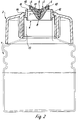
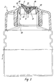
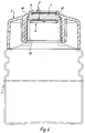
- a bottle 1 made of an elastic material and shown in FIGS. 1 to 4 is closed in the region of its bottle neck with a closure 2 which can be screwed onto the bottle neck 13 by means of a molded screw part 3.
- the closure 2 which, like the bottle 1 in the present exemplary embodiments, is designed as a cylindrical body, is provided in its area partially covering the bottle neck 13 with a cover part 5 which is firmly connected to a support body 4.
- the support body 4 consists of a support body jacket 12, which is supported on the bottle neck 13 with a circumferential attachment 14. In its upper end region facing away from the bottle neck 13, the supporting body jacket is formed on the inside as a sealing surface 15, while, as FIG. 4 shows very clearly, one in the middle region Pivot axis 7 extends from one side of the inner wall of the support body shell 12 to the other side.
- wings 6 are connected on both sides to this pivot axis 7, the connection between the wings 6 and the pivot axis being effected via a film hinge 8, so that a smooth pivoting movement of the wings 6 is possible.
- the entire support body 4, that is, both the support body jacket 12 and the pivot axis 7 and the wings 6 are made of a material, preferably a plastic, with low elasticity.
- the pivot axis 7 and the wings 6 are encased by the cover part 5, which consists of a material of high elasticity.
- the cover part 5 which consists of a material of high elasticity.
- an intimate bond between the wings 6 and the cover part 5 is achieved in that openings 11 in the wings 6 are filled with the material of the cover part 5, so that there is practically a positive connection.
- the outer edge of the cover part 5, which faces the supporting body jacket 12, is designed as a sealing lip 10 which, in the closed position, lies sealingly against the sealing surface 15 of the supporting body jacket 12.
- the lid part 5 is provided in the area of each wing 6 with a pull rib 17 which, due to its elastic forces, pulls the sealing area of the lid part 5 into a closed position for closing.
- FIGS. 1 and 2 represents a support body 4 which has two wings 6, so that the cover part 3 is an embodiment variant in which the cover part can only be opened on one side, with only one pivotable wing being provided for this purpose, while the other side is one with the supporting body jacket 12 firmly connected collar 16 is formed.
- the lid part is opened by squeezing the bottle 1, the bottle contents being pressed against the underside of the lid part 5, and the lid part 5 is thus practically weighed out by the applied pressure force. After this squeezing has ended, ie when there is no longer any pressing pressure on the cover part 5, it is returned to a closed position by the material-related elastic forces. In the closed position, the sealing lip 10 nestles against the sealing surface 1 so that the inside of the bottle is largely protected.
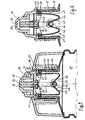
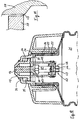
- FIGS. 6 to 11 also designed as a bottle container 21 for liquid or pasty content is provided with a neck 22, on the outer surface of a screw thread 3 for a cap or the like. is arranged.
- a closure cap 25 with an inner end, which is designed as an outwardly standing annular flange 26, optionally with the interposition of a seal 27, against the upper edge 28 of the container neck 22 captured.
- the cap 25 continues the container neck 22 to a certain extent.
- a holder 29 for a centrally arranged filler piece 30 is formed and fastened.
- This holder 29 consists of an outer ring 31, from which individual spokes protrude inwards, on which the filler piece 30, projecting upwards, is stuck. This whole arrangement can be molded in one piece from plastic.
- the filler 30 is designed as a cylindrical body in its The uppermost region projects beyond a central opening in the closure cap 25 and is expediently designed there as a cone 33 with a diameter constriction.
- a nozzle 34 is slidably guided.
- This nozzle 34 consists of a tube section which is provided at its inner end with an outwardly extending flange 35.
- This flange 35 lies with its outer surface on the inner surface of the cap 25 and serves as a guide for the nozzle 34.
- an inwardly directed flange 36 is formed on the cap 25 at the outer end, which with its inner surface against the outer surface of the tubular part the nozzle 34 abuts and this also leads.
- a compression spring 37 is arranged, which is designed as a helical spring, on the one hand abuts against the flange 36 and on the other hand against the flange 35. This compression spring 37 holds the nozzle 34 in the closed position shown in FIG. 6.
- This nozzle is formed at its outer end as a hollow cone 38 with a central opening 39. Between the inner surface of the hollow cone 38 and the flat outer surface of the cone-shaped formation 33 in the outer end of the filler 30, a solid and tight closure forms in the closed state of the nozzle .
- the free inside diameter of the nozzle 34 is substantially larger than the outside diameter of the filling piece 30, so that a further free space is created within the nozzle 34 which surrounds the filling piece 30.
- the compression spring 37 is designed in terms of its spring characteristics such that it holds the nozzle 34 with a tight seal against the filler 10, but yields when the contents of the container 21 are pressed, so that the nozzle 34 is guided within the opposite of the stuck filler 30
- Closure cap 25 is displaced outwards by means of the flanges 35 and 36 and thus releases the nozzle opening 39, so that the position corresponding to FIG. 7 is reached.
- the contents of the container flow then around the filler 30, within the space between the filler and the nozzle to the opening 39. Due to the conically contracted shape 38 of the nozzle 34, which now lies above the upper conical end 33 of the filler 30, the expressed container content is compressed in this area and formed into a compact strand before it can exit the nozzle opening 39.
- the spring 37 is more or less compressed and thus the distance of the nozzle opening 39 is removed from the outer end 33 of the filler piece 30, so that the passage cross section between the upper nozzle end and the filler piece is increased or decreased and accordingly, a larger or smaller amount of the container contents can pass between the outer end 33 of the filler 30 and the outer end of the nozzle 34, which is designed as a hollow cone 38, to the nozzle opening 39, in order to emerge there as a compact, uniformly shaped strand.
- a closure cover 40 is provided which engages over the upper end of the closure cap 25 and is clipped on or screwed on there.
- the closure cover 30 lies with its inner surface firmly against the outer surface of the nozzle 34 and the filler piece 30, so that the nozzle 34 cannot be lifted off the filler piece 30 and thus open the opening 39.
- FIGS. 8 to 10 Another exemplary embodiment is shown in FIGS. 8 to 10, the same reference numerals being used for the same parts.
- the holder ring 31 for the filler 30 is provided with a holder 41 for the bar or leaf spring 42, which is shaped in the form of a W and protrudes into the neck 22 of the container 21.
- the nozzle 34 is provided with lugs 43 which protrude below the filler 30 into the container neck 22 and at its end engage under a crest 45 of the inner angle 46 of the W-shaped spring 42 with a transverse connecting piece 44.
- the outer long legs 47 of the W-shaped spring run approximately parallel in the closed state of the closure to the wall of the container neck 2, as can be seen from FIG. 8.
- the W-shaped spring 22 is slightly tensioned in this state in order to keep the closure closed.
- the W-shaped spring yields and the state corresponding to FIG. 9 is established.
- the nozzle 34 is displaced outward in its guide 35, 36 with respect to the filler 30 and opens the opening 39, the spring 42 being tensioned more by bending its long legs 47 and its inner angle 46.
- the spring 42 pulls the nozzle 34 back against the filler until the opening 39 is closed. All other functions correspond to the description given above in connection with the exemplary embodiment according to FIGS. 6 and 7.
- FIG. 11 shows a greatly enlarged partial section of FIG. 6 or 8.
- a sealing lip 49 is formed on the outside of the flange. This prevents the contents of the container from getting into the nozzle guide and thus impairing the nozzle movement.
- the closure according to the invention is designed in particular with regard to the arrangement of the spring such that it forms a coherent unit. On the one hand, it is therefore easy to manufacture, on the other hand, in a considerably advantageous manner compared to the previously known closures, it is easy to assemble or can be retrofitted or exchanged on any container with a standardized screw neck without any changes or special interventions on the container.
- a lid 53 is placed on the neck 51 of the container 52, which is seated on the upper edge of the neck 51 with an annular flange 54 projecting outwards, possibly with an intermediate layer in the form of a seal .
- the cover 53 is held in place by a cap 55, which has a screw thread 56 is screwed onto the thread arranged on the outside of the neck 51, the cap 55 being provided with an inwardly projecting circular projection 57 which overlaps the flange 54.
- This entire arrangement can be used instead of a conventional screw cap closing the container and can be exchanged for this screw cover, so that each container with a standard screw cover can be provided with this closure.
- the central region of the cover 53 is provided with an opening 58, for example rectangularly limited, on the outer edges of which flaps 59 are hinged 60.
- the flaps 59 are opposite, so that when they are opened they open an opening slot between their mutually opposing edges 61 through which the contents of the container can escape.
- the opening 58 is provided in its center with a beam-shaped support 62, on which the mutually opposing outer edges 61 of the flaps 59 rest in a sealed manner in the closed state.
- these outer edges 61 can be designed such that they cover the beam-shaped support 62 in the closed state on the upper side and on the two side surfaces with an angular profile 63.
- the overall arrangement is preferably designed in such a way that all of the above-described individual parts consist of plastic and are injection molded together in a mold, the hinges 60 being designed as film hinges.
- Arms protruding into the container neck 51 are integrally formed near the two side edges of the flaps 59, and are expediently in one piece and made of the same material as the flaps 59, this material being flexible or resilient due to the cross-sectional configuration of the arms 64.
- the arms 64 are provided with widenings 65, the lower and the two sides of the flaps 59 project downwards and lie against the sides of the openings 58 in the lid 53, so that when the flaps 59 swing open, the container contents cannot emerge towards the sides, but are directed towards the center exclusively through the slot formed between the two flaps 59.
- the arms 64 of the flaps 59 are connected to one another by a crossbar 66.
- a leaf spring 67 is arranged below the cover 53.
- the free ends 68 of the leaf spring 67 are anchored in an annular part 69, which surrounds the inside of the cover 53 between the flanges 54 on the cover and the boundary of the opening 58 in the cover 53.
- the leaf spring 67 is shaped like a large W with long upstanding outer legs 70 and an inner short angle 71, which is connected at the apex 72 to the two arms 64, in such a way that it overlaps the rod 66 connecting the arms 64.
- the W-shaped spring is in a largely relaxed state.
- the arms 64 are also in their normal state and the flaps 59 of the closure are closed.
- the W-shaped spring 67 has a pretension, so that it acts in particular in its central region with the raised inner angle 72 on the connection 66 between the two arms 64, pulling it downward and thus holding the flaps 59 in the closed position.
- the force of the spring 67 is adjusted in such a way that when the pressure on the container contents is not too great, that is to say when the container is compressed, the pressure on the flaps 59 acting inside the container has an opening effect by overcoming the restoring force of the spring 67.
- the flaps 59 open and the position corresponding to FIG.
- an additional securing device can be used, namely a cap, which is not shown here, which lies flat on the two flaps 59 from the outside and above with a central part and with one after the bottom edge is clipped on to the flap 55 or screwed onto it.
- a sealing cap instead of this additional cap, which is similar to the cap 55 and is exchanged for this, the sealing cap, also not shown here, being continued in one piece between the inwardly projecting projection 57, so that this central one Part rests on the outside of the two flaps 59 when screwing onto the thread 56 in a tightly sealing and sealing manner.
- the closure is designed in particular with regard to the arrangement of the spring such that it forms a coherent unit.
Landscapes
- Engineering & Computer Science (AREA)
- Mechanical Engineering (AREA)
- Closures For Containers (AREA)
- Jellies, Jams, And Syrups (AREA)
Applications Claiming Priority (6)
| Application Number | Priority Date | Filing Date | Title |
|---|---|---|---|
| DE19934316145 DE4316145A1 (de) | 1993-05-14 | 1993-05-14 | Aus einem elastischen Material bestehende Flasche oder Tube |
| DE4316145 | 1993-05-14 | ||
| DE9311684U | 1993-08-05 | ||
| DE9311617U | 1993-08-05 | ||
| DE9311617U DE9311617U1 (de) | 1993-08-05 | 1993-08-05 | Verschluß für Behälter mit flüssigem oder pastenförmigem Inhalt |
| DE9311684U DE9311684U1 (de) | 1993-08-05 | 1993-08-05 | Verschluß für Behälter mit flüssigem oder pastenförmigem Inhalt |
Publications (3)
| Publication Number | Publication Date |
|---|---|
| EP0624526A2 true EP0624526A2 (fr) | 1994-11-17 |
| EP0624526A3 EP0624526A3 (fr) | 1995-11-02 |
| EP0624526B1 EP0624526B1 (fr) | 1998-09-16 |
Family
ID=27205083
Family Applications (1)
| Application Number | Title | Priority Date | Filing Date |
|---|---|---|---|
| EP94107271A Expired - Lifetime EP0624526B1 (fr) | 1993-05-14 | 1994-05-10 | Récipient pour contenu liquide ou pâteux |
Country Status (5)
| Country | Link |
|---|---|
| EP (1) | EP0624526B1 (fr) |
| AT (1) | ATE171138T1 (fr) |
| DE (1) | DE59406908D1 (fr) |
| DK (1) | DK0624526T3 (fr) |
| ES (1) | ES2121112T3 (fr) |
Cited By (5)
| Publication number | Priority date | Publication date | Assignee | Title |
|---|---|---|---|---|
| US5927566A (en) * | 1996-07-11 | 1999-07-27 | Aptargroup, Inc. | One-piece dispensing system and method for making same |
| US7077296B2 (en) | 1991-12-06 | 2006-07-18 | Aptargroup, Inc. | Dispensing valve |
| GB2424871B (en) * | 2005-04-04 | 2009-01-28 | Garry Platt | Tamper-resistant bottle closure |
| JP2010131370A (ja) * | 2008-10-15 | 2010-06-17 | Rexam Pharma La Verpilliere | ユーザーに加圧されることによって移動可能な密閉部材を備えた液体吐出装置 |
| WO2011127610A1 (fr) * | 2010-04-12 | 2011-10-20 | Hoffmann Neopac Ag | Clapet anti-retour pour régulation de refoulement dans des tubes, tube muni d'un tel clapet anti-retour et procédé de fabrication d'un tel clapet anti-retour |
Family Cites Families (10)
| Publication number | Priority date | Publication date | Assignee | Title |
|---|---|---|---|---|
| US1911616A (en) * | 1933-05-30 | Lttdwig gsttber | ||
| US2657829A (en) * | 1950-08-17 | 1953-11-03 | Lila M Walch | Collapsible tube closure openable by pressure of the contents |
| DE1246531B (de) * | 1962-01-02 | 1967-08-03 | Karl Walter Eberspaecher | Selbsttaetiger Verschluss fuer Tuben und aehnliche Behaelter |
| BE630794A (fr) * | 1962-04-10 | |||
| GB1107403A (en) * | 1964-05-11 | 1968-03-27 | Robinson E S & A Ltd | Plastic tubes for dispensing pastey or liquid substances |
| DE2314896A1 (de) * | 1973-03-26 | 1974-10-10 | Kalkkuhl Astrid | Selbsttaetiger verschluss fuer quetschtuben |
| DE2609310A1 (de) * | 1975-03-10 | 1976-09-23 | Product Form Ag | Selbstschliessender verschluss fuer behaeltnisse |
| DE3531783A1 (de) * | 1985-09-06 | 1987-03-19 | Helmut Budjin | Verschluss fuer verformbare tuben |
| DE9307083U1 (de) * | 1993-05-11 | 1993-07-22 | Linneweber, Wolfgang, 4800 Bielefeld | Selbstschließender Verschluß |
| DE9307325U1 (de) * | 1993-05-14 | 1993-08-19 | Wolff, Ernst, 33330 Gütersloh | Aus einem elastischen Material bestehende Flasche oder Tube |
-
1994
- 1994-05-10 DK DK94107271T patent/DK0624526T3/da active
- 1994-05-10 DE DE59406908T patent/DE59406908D1/de not_active Expired - Fee Related
- 1994-05-10 EP EP94107271A patent/EP0624526B1/fr not_active Expired - Lifetime
- 1994-05-10 AT AT94107271T patent/ATE171138T1/de not_active IP Right Cessation
- 1994-05-10 ES ES94107271T patent/ES2121112T3/es not_active Expired - Lifetime
Cited By (8)
| Publication number | Priority date | Publication date | Assignee | Title |
|---|---|---|---|---|
| US7077296B2 (en) | 1991-12-06 | 2006-07-18 | Aptargroup, Inc. | Dispensing valve |
| US5927566A (en) * | 1996-07-11 | 1999-07-27 | Aptargroup, Inc. | One-piece dispensing system and method for making same |
| US6112951A (en) * | 1996-07-11 | 2000-09-05 | Aptargroup, Inc. | One-piece dispensing system and method for making same |
| GB2424871B (en) * | 2005-04-04 | 2009-01-28 | Garry Platt | Tamper-resistant bottle closure |
| JP2010131370A (ja) * | 2008-10-15 | 2010-06-17 | Rexam Pharma La Verpilliere | ユーザーに加圧されることによって移動可能な密閉部材を備えた液体吐出装置 |
| US8794490B2 (en) | 2008-10-15 | 2014-08-05 | Rexam Healthcare La Verpilliere | Liquid dispensing device equipped with a sealing component moveable under the effect of pressure by a user |
| WO2011127610A1 (fr) * | 2010-04-12 | 2011-10-20 | Hoffmann Neopac Ag | Clapet anti-retour pour régulation de refoulement dans des tubes, tube muni d'un tel clapet anti-retour et procédé de fabrication d'un tel clapet anti-retour |
| US8740023B2 (en) | 2010-04-12 | 2014-06-03 | Hoffmann Neopac Ag | One-way valve for discharge regulation in tubes, tube with such a one-way valve and method for manufacturing such a one-way valve |
Also Published As
| Publication number | Publication date |
|---|---|
| EP0624526B1 (fr) | 1998-09-16 |
| DE59406908D1 (de) | 1998-10-22 |
| DK0624526T3 (da) | 1999-06-14 |
| EP0624526A3 (fr) | 1995-11-02 |
| ATE171138T1 (de) | 1998-10-15 |
| ES2121112T3 (es) | 1998-11-16 |
Similar Documents
| Publication | Publication Date | Title |
|---|---|---|
| DE69422976T2 (de) | Ausgabevorrichtung versehen mit einem Rückschlagventil | |
| DE69405393T2 (de) | Selbstschliessende anordnung | |
| DE69203819T2 (de) | Einwegventil für einen deformierbaren Behälter. | |
| EP1427647B1 (fr) | Fermeture de distribution destinee a des recipients contenant des liquides | |
| DE60214806T2 (de) | Tube versehen mit einem Ventil | |
| DE69312716T2 (de) | Spendergerät mit hebewerk und gewindestange für stiftförmiges gut und ersatzpatrone dafür | |
| EP0048421A1 (fr) | Distributeur | |
| EP0473994A2 (fr) | Bouteille déformable avec enveloppe interne | |
| EP0727191A2 (fr) | Récipient pour distribuer des masses dentaires | |
| DE2515095A1 (de) | Selbstschliessender verschluss | |
| DE2711591A1 (de) | Behaelter fuer die abgabe von fluessigkeiten | |
| DE3803229A1 (de) | Spender zur portionierten ausgabe pastoeser massen | |
| DE69120429T2 (de) | Dosier- und ausgiessvorrichtung | |
| EP0624526A2 (fr) | Fermeture de récipient avec contenu liquide ou pâteux | |
| DE9311617U1 (de) | Verschluß für Behälter mit flüssigem oder pastenförmigem Inhalt | |
| DE9419268U1 (de) | Spender | |
| EP0287015A1 (fr) | Pulvérisateur | |
| DE69210082T2 (de) | Elastischer Spender für viskose Produkte | |
| DE2904290A1 (de) | Verschlussanordnung | |
| EP0392208B1 (fr) | Soupape pour récipient-distributeur pour matières pâteuses ou visqueuses en forme de tube ou de bouteille | |
| DE69208084T2 (de) | Selbstdichtender Verschluss für einen flexiblen Behälter | |
| EP0221362B1 (fr) | Distributeur pour produits pâteux | |
| DE3207196A1 (de) | Spender zur abgabe fluessiger, pastoeser oder staubfoermiger fuellgueter | |
| DE3829356A1 (de) | Selbstschliessender behaelter-verschluss | |
| DE2158680A1 (de) | Verschluss fuer behaeltnisse |
Legal Events
| Date | Code | Title | Description |
|---|---|---|---|
| PUAI | Public reference made under article 153(3) epc to a published international application that has entered the european phase |
Free format text: ORIGINAL CODE: 0009012 |
|
| AK | Designated contracting states |
Kind code of ref document: A2 Designated state(s): AT BE CH DE DK ES FR GB GR IE IT LI LU NL PT SE |
|
| PUAL | Search report despatched |
Free format text: ORIGINAL CODE: 0009013 |
|
| AK | Designated contracting states |
Kind code of ref document: A3 Designated state(s): AT BE CH DE DK ES FR GB GR IE IT LI LU MC NL PT SE |
|
| 17P | Request for examination filed |
Effective date: 19960308 |
|
| 17Q | First examination report despatched |
Effective date: 19961127 |
|
| GRAG | Despatch of communication of intention to grant |
Free format text: ORIGINAL CODE: EPIDOS AGRA |
|
| GRAG | Despatch of communication of intention to grant |
Free format text: ORIGINAL CODE: EPIDOS AGRA |
|
| GRAH | Despatch of communication of intention to grant a patent |
Free format text: ORIGINAL CODE: EPIDOS IGRA |
|
| GRAH | Despatch of communication of intention to grant a patent |
Free format text: ORIGINAL CODE: EPIDOS IGRA |
|
| ITF | It: translation for a ep patent filed | ||
| RBV | Designated contracting states (corrected) |
Designated state(s): AT BE CH DE DK ES FR GB GR IE IT LI LU NL PT SE |
|
| GRAA | (expected) grant |
Free format text: ORIGINAL CODE: 0009210 |
|
| AK | Designated contracting states |
Kind code of ref document: B1 Designated state(s): AT BE CH DE DK ES FR GB GR IE IT LI LU NL PT SE |
|
| PG25 | Lapsed in a contracting state [announced via postgrant information from national office to epo] |
Ref country code: GR Free format text: LAPSE BECAUSE OF NON-PAYMENT OF DUE FEES Effective date: 19980916 |
|
| REF | Corresponds to: |
Ref document number: 171138 Country of ref document: AT Date of ref document: 19981015 Kind code of ref document: T |
|
| REG | Reference to a national code |
Ref country code: CH Ref legal event code: NV Representative=s name: ISLER & PEDRAZZINI AG Ref country code: CH Ref legal event code: EP |
|
| REF | Corresponds to: |
Ref document number: 59406908 Country of ref document: DE Date of ref document: 19981022 |
|
| REG | Reference to a national code |
Ref country code: ES Ref legal event code: FG2A Ref document number: 2121112 Country of ref document: ES Kind code of ref document: T3 |
|
| GBT | Gb: translation of ep patent filed (gb section 77(6)(a)/1977) |
Effective date: 19981029 |
|
| REG | Reference to a national code |
Ref country code: IE Ref legal event code: FG4D Free format text: GERMAN |
|
| REG | Reference to a national code |
Ref country code: PT Ref legal event code: SC4A Free format text: AVAILABILITY OF NATIONAL TRANSLATION Effective date: 19980918 |
|
| ET | Fr: translation filed | ||
| PG25 | Lapsed in a contracting state [announced via postgrant information from national office to epo] |
Ref country code: LU Free format text: LAPSE BECAUSE OF NON-PAYMENT OF DUE FEES Effective date: 19990510 Ref country code: IE Free format text: LAPSE BECAUSE OF NON-PAYMENT OF DUE FEES Effective date: 19990510 Ref country code: GB Free format text: LAPSE BECAUSE OF NON-PAYMENT OF DUE FEES Effective date: 19990510 Ref country code: DK Free format text: LAPSE BECAUSE OF NON-PAYMENT OF DUE FEES Effective date: 19990510 Ref country code: AT Free format text: LAPSE BECAUSE OF NON-PAYMENT OF DUE FEES Effective date: 19990510 |
|
| PG25 | Lapsed in a contracting state [announced via postgrant information from national office to epo] |
Ref country code: SE Free format text: LAPSE BECAUSE OF NON-PAYMENT OF DUE FEES Effective date: 19990511 Ref country code: ES Free format text: LAPSE BECAUSE OF NON-PAYMENT OF DUE FEES Effective date: 19990511 |
|
| PG25 | Lapsed in a contracting state [announced via postgrant information from national office to epo] |
Ref country code: LI Free format text: LAPSE BECAUSE OF NON-PAYMENT OF DUE FEES Effective date: 19990531 Ref country code: CH Free format text: LAPSE BECAUSE OF NON-PAYMENT OF DUE FEES Effective date: 19990531 Ref country code: BE Free format text: LAPSE BECAUSE OF NON-PAYMENT OF DUE FEES Effective date: 19990531 |
|
| REG | Reference to a national code |
Ref country code: DK Ref legal event code: T3 |
|
| PLBE | No opposition filed within time limit |
Free format text: ORIGINAL CODE: 0009261 |
|
| STAA | Information on the status of an ep patent application or granted ep patent |
Free format text: STATUS: NO OPPOSITION FILED WITHIN TIME LIMIT |
|
| 26N | No opposition filed | ||
| BERE | Be: lapsed |
Owner name: WOLFF ERNST Effective date: 19990531 |
|
| PG25 | Lapsed in a contracting state [announced via postgrant information from national office to epo] |
Ref country code: PT Free format text: LAPSE BECAUSE OF NON-PAYMENT OF DUE FEES Effective date: 19991130 |
|
| PG25 | Lapsed in a contracting state [announced via postgrant information from national office to epo] |
Ref country code: NL Free format text: LAPSE BECAUSE OF NON-PAYMENT OF DUE FEES Effective date: 19991201 |
|
| GBPC | Gb: european patent ceased through non-payment of renewal fee |
Effective date: 19990510 |
|
| REG | Reference to a national code |
Ref country code: CH Ref legal event code: PL |
|
| EUG | Se: european patent has lapsed |
Ref document number: 94107271.2 |
|
| PG25 | Lapsed in a contracting state [announced via postgrant information from national office to epo] |
Ref country code: FR Free format text: LAPSE BECAUSE OF NON-PAYMENT OF DUE FEES Effective date: 20000131 |
|
| NLV4 | Nl: lapsed or anulled due to non-payment of the annual fee |
Effective date: 19991201 |
|
| PG25 | Lapsed in a contracting state [announced via postgrant information from national office to epo] |
Ref country code: DE Free format text: LAPSE BECAUSE OF NON-PAYMENT OF DUE FEES Effective date: 20000301 |
|
| REG | Reference to a national code |
Ref country code: FR Ref legal event code: ST |
|
| REG | Reference to a national code |
Ref country code: PT Ref legal event code: MM4A Free format text: LAPSE DUE TO NON-PAYMENT OF FEES Effective date: 19991130 |
|
| REG | Reference to a national code |
Ref country code: DK Ref legal event code: EBP |
|
| REG | Reference to a national code |
Ref country code: ES Ref legal event code: FD2A Effective date: 20030203 |
|
| PG25 | Lapsed in a contracting state [announced via postgrant information from national office to epo] |
Ref country code: IT Free format text: LAPSE BECAUSE OF NON-PAYMENT OF DUE FEES;WARNING: LAPSES OF ITALIAN PATENTS WITH EFFECTIVE DATE BEFORE 2007 MAY HAVE OCCURRED AT ANY TIME BEFORE 2007. THE CORRECT EFFECTIVE DATE MAY BE DIFFERENT FROM THE ONE RECORDED. Effective date: 20050510 |