EP0624721A1 - Méthode d'identification de l'origine de pannes dans un système de régulation du mélange d'un moteur à combustion interne - Google Patents
Méthode d'identification de l'origine de pannes dans un système de régulation du mélange d'un moteur à combustion interne Download PDFInfo
- Publication number
- EP0624721A1 EP0624721A1 EP93107898A EP93107898A EP0624721A1 EP 0624721 A1 EP0624721 A1 EP 0624721A1 EP 93107898 A EP93107898 A EP 93107898A EP 93107898 A EP93107898 A EP 93107898A EP 0624721 A1 EP0624721 A1 EP 0624721A1
- Authority
- EP
- European Patent Office
- Prior art keywords
- probe
- lambda
- value
- lam
- internal combustion
- Prior art date
- Legal status (The legal status is an assumption and is not a legal conclusion. Google has not performed a legal analysis and makes no representation as to the accuracy of the status listed.)
- Granted
Links
Images
Classifications
-
- F—MECHANICAL ENGINEERING; LIGHTING; HEATING; WEAPONS; BLASTING
- F02—COMBUSTION ENGINES; HOT-GAS OR COMBUSTION-PRODUCT ENGINE PLANTS
- F02D—CONTROLLING COMBUSTION ENGINES
- F02D41/00—Electrical control of supply of combustible mixture or its constituents
- F02D41/02—Circuit arrangements for generating control signals
- F02D41/14—Introducing closed-loop corrections
- F02D41/1438—Introducing closed-loop corrections using means for determining characteristics of the combustion gases; Sensors therefor
- F02D41/1493—Details
- F02D41/1495—Detection of abnormalities in the air/fuel ratio feedback system
-
- F—MECHANICAL ENGINEERING; LIGHTING; HEATING; WEAPONS; BLASTING
- F02—COMBUSTION ENGINES; HOT-GAS OR COMBUSTION-PRODUCT ENGINE PLANTS
- F02D—CONTROLLING COMBUSTION ENGINES
- F02D41/00—Electrical control of supply of combustible mixture or its constituents
- F02D41/02—Circuit arrangements for generating control signals
- F02D41/14—Introducing closed-loop corrections
- F02D41/1438—Introducing closed-loop corrections using means for determining characteristics of the combustion gases; Sensors therefor
- F02D41/1493—Details
- F02D41/1494—Control of sensor heater
Definitions
- the invention relates to a method for differentiating the causes of faults in the mixture formation or mixture control system of an internal combustion engine according to the preamble of claim 1.
- Control devices are used for this purpose, which operate in dependence on a signal supplied in the exhaust system of the machine, the so-called lambda probe. This signal is compared with a reference voltage corresponding to an optimal value and a control signal for influencing the air / fuel supply is derived from the comparison.
- a prerequisite for the proper functioning of such a control device is that the lambda probe is working properly.
- the known lambda probes which determine the oxygen concentration of the exhaust gas, the operational readiness is only guaranteed from a certain temperature. So that the lambda probe reaches its operating temperature as quickly as possible and the probe temperature can then be kept at a predetermined, constant value, an additional heating device is provided which, in addition to heating the lambda probe by the exhaust gases, ensures that it is ready for operation quickly.
- the lambda probes used in devices of this type are constructed in such a way that they emit a relatively high voltage in the case of a rich air / fuel mixture and a low voltage in relation to a lean air / fuel mixture.
- the voltage emitted by the lambda probe is therefore on the one hand near zero (for example a few mV) in the case of a lean mixture ( ⁇ > 1) and not or only with great difficulty from an interruption in the lead wires of the lambda probe - hereinafter referred to as a line interruption - or from to distinguish a short circuit of the signal line to ground.
- the output voltage of the lambda probe with a rich mixture ( ⁇ ⁇ 1) is relatively high and, even in the event of a short-circuit of the lambda probe lead against the on-board voltage or against the supply voltage of the electronic control device, it can assume values which are above a limit value for rich mixture and pretend a rich mixture, it is also necessary to detect the type of fault.
- the invention is therefore based on the object of specifying a method which enables a simple distinction to be made between a mixture formation error and a defective, heated lambda probe.
- a prerequisite for carrying out this method to differentiate the causes of faults in the mixture formation or mixture control system is that the lambda control is active, the lambda probe is ready for operation and the lambda probe heater is not defective. For this reason, the probe heating is checked at the first start and each time it is started again. If the query is negative, ie the probe heating is not ready for operation, this can be announced to the driver, for example, by a signal lamp. So he can take appropriate measures to restore the functional readiness of the probe heater and the described method is not even started.
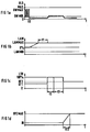
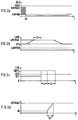
- FIGS 1a and 2a are some (only qualitative shown voltage jumps of the lambda probe output voltage, hereinafter simply referred to as the probe voltage ULS.
- a maximum value MAX and a lower diagnosis limit value GWMIN and an upper diagnosis limit value GWMAX are shown in these time diagrams.
- the probe voltage ULS drops below the limit value GWMIN and also remains almost zero.
- the air / fuel mixture is enriched by the lambda controller.
- Figures 1b and 2b show this procedure of the lambda control.
- LAM 0
- an attempt is made to compensate for the control deviation (mixture which is too lean) by increasing the lambda controller value LAM up to a maximum value LAM MAX, the so-called controller stop.
- the lambda controller remains at the controller stop.
- a certain dwell time t1 is now waited for in order to exclude other system errors from the diagnosis.
- the maximum and minimum values are around 25%, ie the lambda controller can enrich up to 25% or lean 25%.
- the lambda probe heating is used for this.
- the electrical heating of the lambda probe takes place in a manner known per se by clocked activation with a pulse duty factor, which is composed of a pilot control value and a lambda probe voltage regulator value and is stored in a characteristic diagram of the electronic control device of the internal combustion engine.
- a pulse duty factor which is composed of a pilot control value and a lambda probe voltage regulator value and is stored in a characteristic diagram of the electronic control device of the internal combustion engine.
- the lambda probe heating is actuated with a pulse duty factor corresponding to a map value KF1 (FIGS. 1c, 2c) in order to keep the temperature of the lambda probe constant at a value dependent on operating parameters of the internal combustion engine .
- the lambda probe heating is controlled to a 100% duty cycle and remains at this value for a period of time t2 + t3 (e.g. 5 seconds + 6 seconds).
- This time period depends on the system, e.g. of the probe structure and the outside temperature. Since the probe voltage is strongly dependent on the temperature (the probe voltage rises as the temperature rises) and thus also the voltage that is emitted in lean operation, the probe voltage ULS must rise again if the probe is intact due to the increased energy supply from the heating. From here, the preparation for the detection of whether there is a mixture error or a probe error begins.
- a time counter is then initialized (jump to initialization value IN, Figure 1d). If the value EPZ MAX ( Figure 1d, t2) is reached by the counter, "permanent" is recognized for mixture errors and e.g. entered in a fault memory. In addition, a diagnostic lamp can be activated and the measures required for an emergency run can be taken. Lambda control remains active, i.e. the lambda controller remains at the controller stop LAM MAX ( Figure 1b). A mixture error permanent lean can e.g. in that leakage air enters the intake area of the internal combustion engine in an uncontrolled manner.
- the probe voltage ULS remains below the diagnostic limit value GWMIN (FIG. 2a) after the heating power has been increased
- the detection of lambda probe errors is released after the period t2.
- the counter is initialized again and runs up until it reaches the EPZ MAX value (after the time tE1).
- the fault type Lambda probe fault is concluded, ie there is either a short circuit in the lead wires of the Lambda probe to ground or an interruption in the leads. This type of error too is stored in a fault memory and a diagnostic lamp and emergency operation functions are activated that affect this fault.
- the lambda controller value LAM is reduced to 0 and the lambda controller then remains switched off (FIG. 2b).
- a corresponding procedure is used if a distinction is to be made as to whether there is a "permanent fat" mixture error or a probe error. Since the lambda probe emits a relatively high voltage when the mixture is rich, an upper diagnostic limit value GWMAX is set to differentiate the causes of the fault. If this limit value is exceeded and the lambda control runs to the controller limit LAM MIN ( Figure 1b, 2b), the heating for the lambda probe is switched off and, based on the temperature dependence of the probe voltage mentioned, it is now checked whether the upper diagnostic limit value is again is undercut. The further evaluation takes place according to the described method.
- a mixture fault "permanent grease” can occur, for example, through faulty air volume or air mass determination, while a, a rich mixture of pretending probe errors can lie in the fact that the leads of the probe are short-circuited against the supply line of the electronic control device (typically 5V) or against the on-board voltage (12V ) having.
- the described method can be used in all internal combustion engines with a lambda control device which have a heated lambda probe, regardless of the type of mixture formation system.
Landscapes
- Engineering & Computer Science (AREA)
- Chemical & Material Sciences (AREA)
- Combustion & Propulsion (AREA)
- Mechanical Engineering (AREA)
- General Engineering & Computer Science (AREA)
- Electrical Control Of Air Or Fuel Supplied To Internal-Combustion Engine (AREA)
- Measuring Oxygen Concentration In Cells (AREA)
- Combined Controls Of Internal Combustion Engines (AREA)
- Testing Of Engines (AREA)
Priority Applications (4)
| Application Number | Priority Date | Filing Date | Title |
|---|---|---|---|
| DE59304054T DE59304054D1 (de) | 1993-05-14 | 1993-05-14 | Verfahren zur Unterscheidung der Fehlerursachen im Gemischbildungs- bzw. Gemischregelungssystem einer Brennkraftmaschine |
| EP93107898A EP0624721B1 (fr) | 1993-05-14 | 1993-05-14 | Méthode d'identification de l'origine de pannes dans un système de régulation du mélange d'un moteur à combustion interne |
| US08/243,328 US5462040A (en) | 1993-05-14 | 1994-05-16 | Method for distinguishing causes of error in the mixture forming or mixture regulating system of an internal combustion engine |
| JP6124674A JPH06330803A (ja) | 1993-05-14 | 1994-05-16 | 内燃機関における混合気形成系または混合気制御系の障害原因を識別する方法 |
Applications Claiming Priority (1)
| Application Number | Priority Date | Filing Date | Title |
|---|---|---|---|
| EP93107898A EP0624721B1 (fr) | 1993-05-14 | 1993-05-14 | Méthode d'identification de l'origine de pannes dans un système de régulation du mélange d'un moteur à combustion interne |
Publications (2)
| Publication Number | Publication Date |
|---|---|
| EP0624721A1 true EP0624721A1 (fr) | 1994-11-17 |
| EP0624721B1 EP0624721B1 (fr) | 1996-10-02 |
Family
ID=8212909
Family Applications (1)
| Application Number | Title | Priority Date | Filing Date |
|---|---|---|---|
| EP93107898A Expired - Lifetime EP0624721B1 (fr) | 1993-05-14 | 1993-05-14 | Méthode d'identification de l'origine de pannes dans un système de régulation du mélange d'un moteur à combustion interne |
Country Status (4)
| Country | Link |
|---|---|
| US (1) | US5462040A (fr) |
| EP (1) | EP0624721B1 (fr) |
| JP (1) | JPH06330803A (fr) |
| DE (1) | DE59304054D1 (fr) |
Cited By (10)
| Publication number | Priority date | Publication date | Assignee | Title |
|---|---|---|---|---|
| FR2739413A1 (fr) * | 1995-09-29 | 1997-04-04 | Siemens Ag | Procede de controle de la capacite de fonctionnement d'un dispositif de chauffage pour sonde de gaz d'echappement |
| FR2756389A1 (fr) * | 1996-11-22 | 1998-05-29 | Renault | Procede de controle d'un capteur equipant un moteur a combustion interne |
| GB2290882B (en) * | 1994-06-29 | 1998-09-16 | Ford Motor Co | Engine air/fuel control |
| EP1959121A1 (fr) * | 2007-02-14 | 2008-08-20 | Ford Global Technologies, LLC | Surveillance de l'activation d'un capteur |
| DE102007034251A1 (de) * | 2007-07-23 | 2009-01-29 | Continental Automotive Gmbh | Fehleranalyseverfahren für eine Lambda-Sonde |
| WO2009109421A1 (fr) * | 2008-03-07 | 2009-09-11 | Robert Bosch Gmbh | Procédé et dispositif de différenciation entre une concentration attendue par erreur et une concentration détectée par erreur d’une composante des gaz d’échappement d’un moteur à combustion interne |
| EP2090404A3 (fr) * | 2008-02-13 | 2010-06-23 | HILTI Aktiengesellschaft | Outil d'entraînement à combustion de gaz |
| DE102006052985B4 (de) * | 2006-11-10 | 2015-08-06 | Volkswagen Ag | Verfahren zum Betreiben einer Brennkraftmaschine mit bivalenter Brennstoffzufuhr |
| CN105445341A (zh) * | 2014-09-12 | 2016-03-30 | 达尔生技股份有限公司 | 电化学的检测试片异常的检测方法 |
| CN113833567A (zh) * | 2020-06-23 | 2021-12-24 | 北京大学 | 一种机理数据融合的柴油机涡轮增压器故障检测方法 |
Families Citing this family (7)
| Publication number | Priority date | Publication date | Assignee | Title |
|---|---|---|---|---|
| DE19513490A1 (de) * | 1995-04-14 | 1996-10-17 | Roth Technik Gmbh | Beheizbarer Gassensor |
| JPH09100735A (ja) * | 1995-10-06 | 1997-04-15 | Honda Motor Co Ltd | 内燃機関の空燃比センサ劣化検出装置 |
| DE10128969C1 (de) * | 2001-06-15 | 2002-12-12 | Audi Ag | Verfahren zur Diagnose einer Führungssonde |
| US6684869B2 (en) * | 2002-01-11 | 2004-02-03 | Ford Global Technologies, Llc | System and method for detecting an air leak in an engine |
| DE102004050092B3 (de) * | 2004-10-14 | 2006-04-13 | Siemens Ag | Verfahren zur Regelung des Lambda-Wertes einer Brennkraftmaschine |
| EP2013464B1 (fr) * | 2006-04-18 | 2009-12-23 | Iav Gmbh Ingenieurgesellschaft Auto Und Verkehr | Procédé pour régler le rapport air-carburant d'un moteur à combustion interne |
| EP2336759B1 (fr) * | 2008-10-09 | 2018-11-21 | Toyota Jidosha Kabushiki Kaisha | Dispositif d'évaluation d'activité d'un détecteur de gaz d'échappement et dispositif de commande d'un moteur à combustion interne |
Citations (2)
| Publication number | Priority date | Publication date | Assignee | Title |
|---|---|---|---|---|
| GB2219093A (en) * | 1988-04-25 | 1989-11-29 | Honda Motor Co Ltd | Detecting failure of exhaust gas component sensing device |
| WO1990006431A1 (fr) * | 1988-11-29 | 1990-06-14 | Robert Bosch Gmbh | Procede et dispositif permettant de detecter la defectuosite d'une sonde lambda |
Family Cites Families (1)
| Publication number | Priority date | Publication date | Assignee | Title |
|---|---|---|---|---|
| KR940004344B1 (ko) * | 1990-07-10 | 1994-05-23 | 미쯔비시지도오샤고오교오 가부시기가이샤 | 공연비 제어장치 |
-
1993
- 1993-05-14 DE DE59304054T patent/DE59304054D1/de not_active Expired - Fee Related
- 1993-05-14 EP EP93107898A patent/EP0624721B1/fr not_active Expired - Lifetime
-
1994
- 1994-05-16 US US08/243,328 patent/US5462040A/en not_active Expired - Fee Related
- 1994-05-16 JP JP6124674A patent/JPH06330803A/ja not_active Withdrawn
Patent Citations (2)
| Publication number | Priority date | Publication date | Assignee | Title |
|---|---|---|---|---|
| GB2219093A (en) * | 1988-04-25 | 1989-11-29 | Honda Motor Co Ltd | Detecting failure of exhaust gas component sensing device |
| WO1990006431A1 (fr) * | 1988-11-29 | 1990-06-14 | Robert Bosch Gmbh | Procede et dispositif permettant de detecter la defectuosite d'une sonde lambda |
Non-Patent Citations (1)
| Title |
|---|
| PATENT ABSTRACTS OF JAPAN vol. 016, no. 434 (M-1308)10. September 1992 & JP-A-04 148 038 ( NISSAN MOTOR CO LTD ) 21. Mai 1992 * |
Cited By (13)
| Publication number | Priority date | Publication date | Assignee | Title |
|---|---|---|---|---|
| GB2290882B (en) * | 1994-06-29 | 1998-09-16 | Ford Motor Co | Engine air/fuel control |
| FR2739413A1 (fr) * | 1995-09-29 | 1997-04-04 | Siemens Ag | Procede de controle de la capacite de fonctionnement d'un dispositif de chauffage pour sonde de gaz d'echappement |
| FR2756389A1 (fr) * | 1996-11-22 | 1998-05-29 | Renault | Procede de controle d'un capteur equipant un moteur a combustion interne |
| DE102006052985B4 (de) * | 2006-11-10 | 2015-08-06 | Volkswagen Ag | Verfahren zum Betreiben einer Brennkraftmaschine mit bivalenter Brennstoffzufuhr |
| EP1959121A1 (fr) * | 2007-02-14 | 2008-08-20 | Ford Global Technologies, LLC | Surveillance de l'activation d'un capteur |
| US8386155B2 (en) | 2007-07-23 | 2013-02-26 | Continental Automotive Gmbh | Fault analysis method for a lambda probe |
| DE102007034251B4 (de) * | 2007-07-23 | 2013-12-05 | Continental Automotive Gmbh | Fehleranalyseverfahren für eine Lambda-Sonde, Motorsteuerung für eine Brennkraftmaschine zur Ausführung des Fehleranalyseverfahrens sowie Programmspeicher |
| DE102007034251A1 (de) * | 2007-07-23 | 2009-01-29 | Continental Automotive Gmbh | Fehleranalyseverfahren für eine Lambda-Sonde |
| EP2090404A3 (fr) * | 2008-02-13 | 2010-06-23 | HILTI Aktiengesellschaft | Outil d'entraînement à combustion de gaz |
| WO2009109421A1 (fr) * | 2008-03-07 | 2009-09-11 | Robert Bosch Gmbh | Procédé et dispositif de différenciation entre une concentration attendue par erreur et une concentration détectée par erreur d’une composante des gaz d’échappement d’un moteur à combustion interne |
| CN105445341A (zh) * | 2014-09-12 | 2016-03-30 | 达尔生技股份有限公司 | 电化学的检测试片异常的检测方法 |
| CN105445341B (zh) * | 2014-09-12 | 2018-10-16 | 达尔生技股份有限公司 | 电化学的检测试片异常的检测方法 |
| CN113833567A (zh) * | 2020-06-23 | 2021-12-24 | 北京大学 | 一种机理数据融合的柴油机涡轮增压器故障检测方法 |
Also Published As
| Publication number | Publication date |
|---|---|
| US5462040A (en) | 1995-10-31 |
| JPH06330803A (ja) | 1994-11-29 |
| DE59304054D1 (de) | 1996-11-07 |
| EP0624721B1 (fr) | 1996-10-02 |
Similar Documents
| Publication | Publication Date | Title |
|---|---|---|
| EP0624721B1 (fr) | Méthode d'identification de l'origine de pannes dans un système de régulation du mélange d'un moteur à combustion interne | |
| EP1327138B1 (fr) | Procede et dispositif d'autodiagnostic d'un capteur de nox | |
| DE3500594C2 (de) | Zumeßsystem für eine Brennkraftmaschine zur Beeinflussung des Betriebsgemisches | |
| EP0860597B1 (fr) | Méthode de test des connections de sondes lambda | |
| DE4324445C2 (de) | Anordnung zum Unterbrechen des Betriebs eines eine Verbrennungskraftmaschine aufweisenden Kraffahrzeugs | |
| DE2815109C2 (de) | Überwachungsvorrichtung für Regeleinrichtungen mit geschlossener Regelschleife für das Luft/Brennstoff-Verhältnis von Brennkraftmaschinen | |
| DE2541823A1 (de) | Detektorsystem zum feststellen des ausfalles eines abgasfuehlers bei einer brennkraftmaschine | |
| DE3624441A1 (de) | Diagnoseverfahren zur quantitativen ueberpruefung von stellgliedern bei brennkraftmaschinen | |
| DE19733107C2 (de) | Verfahren zur Überprüfung der Funktionsfähigkeit einer Lambdasonde | |
| EP0546318A1 (fr) | Méthode et dispositif pour la détermination du rendement de conversion d'un catalyseur | |
| DE2919220C2 (fr) | ||
| DE19752965A1 (de) | Verfahren zur Überwachung des Abgasreinigungssystems einer fremdgezündeten Brennkraftmaschine | |
| DE19536577C2 (de) | Verfahren zum Überprüfen der Funktionsfähigkeit einer Abgassonden-Heizeinrichtung | |
| DE3230211A1 (de) | Luft/kraftstoff-verhaeltnis-rueckkopplungssteuersystem zur verwendung in einer brennkraftmaschine | |
| DE4309854A1 (de) | Verfahren und Vorrichtung zur Steuerung der Sekundärluftzufuhr für eine Brennkraftmaschine | |
| DE19536798A1 (de) | Vorrichtung zum Erfassen der Verringerung der Reinigungskapazität eines Katalysators zum Reinigen von Abgas eines Verbrennungsmotors | |
| DE4324447C2 (de) | Anordnung und Verfahren zum Unterbrechen des Betriebs eines eine Verbrennungskraftmaschine aufweisenden Kraftfahrzeugs | |
| DE4324391C2 (de) | Anordnung und Verfahren zum Unterbrechen des Betriebes eines eine Verbrennungskraftmaschine aufweisenden Kraftfahrzeuges | |
| DE102009054935A1 (de) | Verfahren und Vorrichtung zur Diagnose der Dynamik eines Abgassensors | |
| EP0757168A2 (fr) | Méthode et dispositif pour la commande d'un moteur à combustion interne | |
| DE3014633A1 (de) | Verfahren und vorrichtung zur rueckkopplungssteuerung einer brennkraftmaschine | |
| DE4243493A1 (de) | Verfahren und Vorrichtung zur Überwachung einer Steuereinrichtung | |
| DE19537381A1 (de) | Verfahren und Vorrichtung zur Steuerung einer Brennkraftmaschine | |
| DE19818332A1 (de) | Verfahren zur Erfassung eines Elementenwiderstands eines Gaskonzentrationssensors | |
| DE3613396A1 (de) | Ueberwachungseinrichtung fuer einen sauerstoffsensor |
Legal Events
| Date | Code | Title | Description |
|---|---|---|---|
| PUAI | Public reference made under article 153(3) epc to a published international application that has entered the european phase |
Free format text: ORIGINAL CODE: 0009012 |
|
| AK | Designated contracting states |
Kind code of ref document: A1 Designated state(s): AT BE CH DE DK ES FR GB GR IE IT LI LU MC NL PT SE |
|
| 17P | Request for examination filed |
Effective date: 19941205 |
|
| RBV | Designated contracting states (corrected) |
Designated state(s): DE FR GB IT |
|
| GRAG | Despatch of communication of intention to grant |
Free format text: ORIGINAL CODE: EPIDOS AGRA |
|
| GRAH | Despatch of communication of intention to grant a patent |
Free format text: ORIGINAL CODE: EPIDOS IGRA |
|
| 17Q | First examination report despatched |
Effective date: 19960321 |
|
| GRAH | Despatch of communication of intention to grant a patent |
Free format text: ORIGINAL CODE: EPIDOS IGRA |
|
| GRAA | (expected) grant |
Free format text: ORIGINAL CODE: 0009210 |
|
| AK | Designated contracting states |
Kind code of ref document: B1 Designated state(s): DE FR GB IT |
|
| PG25 | Lapsed in a contracting state [announced via postgrant information from national office to epo] |
Ref country code: IT Free format text: LAPSE BECAUSE OF FAILURE TO SUBMIT A TRANSLATION OF THE DESCRIPTION OR TO PAY THE FEE WITHIN THE PRE;WARNING: LAPSES OF ITALIAN PATENTS WITH EFFECTIVE DATE BEFORE 2007 MAY HAVE OCCURRED AT ANY TIME BEFORE 2007. THE CORRECT EFFECTIVE DATE MAY BE DIFFERENT FROM THE ONE RECORDED.SCRIBED TIME-LIMIT Effective date: 19961002 |
|
| REF | Corresponds to: |
Ref document number: 59304054 Country of ref document: DE Date of ref document: 19961107 |
|
| ET | Fr: translation filed | ||
| GBT | Gb: translation of ep patent filed (gb section 77(6)(a)/1977) |
Effective date: 19961206 |
|
| PGFP | Annual fee paid to national office [announced via postgrant information from national office to epo] |
Ref country code: GB Payment date: 19970418 Year of fee payment: 5 |
|
| PGFP | Annual fee paid to national office [announced via postgrant information from national office to epo] |
Ref country code: FR Payment date: 19970521 Year of fee payment: 5 |
|
| PLBE | No opposition filed within time limit |
Free format text: ORIGINAL CODE: 0009261 |
|
| 26N | No opposition filed | ||
| PG25 | Lapsed in a contracting state [announced via postgrant information from national office to epo] |
Ref country code: GB Free format text: LAPSE BECAUSE OF NON-PAYMENT OF DUE FEES Effective date: 19980514 |
|
| PG25 | Lapsed in a contracting state [announced via postgrant information from national office to epo] |
Ref country code: FR Free format text: LAPSE BECAUSE OF NON-PAYMENT OF DUE FEES Effective date: 19980531 |
|
| GBPC | Gb: european patent ceased through non-payment of renewal fee |
Effective date: 19980514 |
|
| REG | Reference to a national code |
Ref country code: FR Ref legal event code: ST |
|
| PGFP | Annual fee paid to national office [announced via postgrant information from national office to epo] |
Ref country code: DE Payment date: 20080620 Year of fee payment: 16 |
|
| PG25 | Lapsed in a contracting state [announced via postgrant information from national office to epo] |
Ref country code: DE Free format text: LAPSE BECAUSE OF NON-PAYMENT OF DUE FEES Effective date: 20091201 |