EP0624729A1 - Pompe double-diaphragme actionnée par air - Google Patents
Pompe double-diaphragme actionnée par air Download PDFInfo
- Publication number
- EP0624729A1 EP0624729A1 EP94303411A EP94303411A EP0624729A1 EP 0624729 A1 EP0624729 A1 EP 0624729A1 EP 94303411 A EP94303411 A EP 94303411A EP 94303411 A EP94303411 A EP 94303411A EP 0624729 A1 EP0624729 A1 EP 0624729A1
- Authority
- EP
- European Patent Office
- Prior art keywords
- pump
- shell
- inlet
- diaphragm
- air
- Prior art date
- Legal status (The legal status is an assumption and is not a legal conclusion. Google has not performed a legal analysis and makes no representation as to the accuracy of the status listed.)
- Granted
Links
- 239000012530 fluid Substances 0.000 claims description 30
- 239000000463 material Substances 0.000 claims description 15
- 238000005086 pumping Methods 0.000 claims description 11
- 238000010276 construction Methods 0.000 claims description 8
- 238000000034 method Methods 0.000 claims description 7
- 239000007787 solid Substances 0.000 claims description 2
- 230000002452 interceptive effect Effects 0.000 claims 1
- 125000006850 spacer group Chemical group 0.000 claims 1
- 238000009428 plumbing Methods 0.000 abstract description 4
- POIUWJQBRNEFGX-XAMSXPGMSA-N cathelicidin Chemical compound C([C@@H](C(=O)N[C@@H](CCCNC(N)=N)C(=O)N[C@@H](CCCCN)C(=O)N[C@@H](CO)C(=O)N[C@@H](CCCCN)C(=O)N[C@@H](CCC(O)=O)C(=O)N[C@@H](CCCCN)C(=O)N[C@@H]([C@@H](C)CC)C(=O)NCC(=O)N[C@@H](CCCCN)C(=O)N[C@@H](CCC(O)=O)C(=O)N[C@@H](CC=1C=CC=CC=1)C(=O)N[C@@H](CCCCN)C(=O)N[C@@H](CCCNC(N)=N)C(=O)N[C@@H]([C@@H](C)CC)C(=O)N[C@@H](C(C)C)C(=O)N[C@@H](CCC(N)=O)C(=O)N[C@@H](CCCNC(N)=N)C(=O)N[C@@H]([C@@H](C)CC)C(=O)N[C@@H](CCCCN)C(=O)N[C@@H](CC(O)=O)C(=O)N[C@@H](CC=1C=CC=CC=1)C(=O)N[C@@H](CC(C)C)C(=O)N[C@@H](CCCNC(N)=N)C(=O)N[C@@H](CC(N)=O)C(=O)N[C@@H](CC(C)C)C(=O)N[C@@H](C(C)C)C(=O)N1[C@@H](CCC1)C(=O)N[C@@H](CCCNC(N)=N)C(=O)N[C@@H]([C@@H](C)O)C(=O)N[C@@H](CCC(O)=O)C(=O)N[C@@H](CO)C(O)=O)NC(=O)[C@H](CC=1C=CC=CC=1)NC(=O)[C@H](CC(O)=O)NC(=O)CNC(=O)[C@H](CC(C)C)NC(=O)[C@@H](N)CC(C)C)C1=CC=CC=C1 POIUWJQBRNEFGX-XAMSXPGMSA-N 0.000 description 5
- 230000009977 dual effect Effects 0.000 description 5
- 230000000712 assembly Effects 0.000 description 2
- 238000000429 assembly Methods 0.000 description 2
- 230000013011 mating Effects 0.000 description 2
- 239000012528 membrane Substances 0.000 description 2
- 239000004743 Polypropylene Substances 0.000 description 1
- DHKHKXVYLBGOIT-UHFFFAOYSA-N acetaldehyde Diethyl Acetal Natural products CCOC(C)OCC DHKHKXVYLBGOIT-UHFFFAOYSA-N 0.000 description 1
- 125000002777 acetyl group Chemical class [H]C([H])([H])C(*)=O 0.000 description 1
- 230000000694 effects Effects 0.000 description 1
- 238000004519 manufacturing process Methods 0.000 description 1
- -1 polypropylene Polymers 0.000 description 1
- 229920001155 polypropylene Polymers 0.000 description 1
- 239000002904 solvent Substances 0.000 description 1
- 239000000126 substance Substances 0.000 description 1
- 239000012815 thermoplastic material Substances 0.000 description 1
Images


Classifications
-
- F—MECHANICAL ENGINEERING; LIGHTING; HEATING; WEAPONS; BLASTING
- F04—POSITIVE - DISPLACEMENT MACHINES FOR LIQUIDS; PUMPS FOR LIQUIDS OR ELASTIC FLUIDS
- F04B—POSITIVE-DISPLACEMENT MACHINES FOR LIQUIDS; PUMPS
- F04B43/00—Machines, pumps, or pumping installations having flexible working members
- F04B43/02—Machines, pumps, or pumping installations having flexible working members having plate-like flexible members, e.g. diaphragms
- F04B43/06—Pumps having fluid drive
- F04B43/073—Pumps having fluid drive the actuating fluid being controlled by at least one valve
- F04B43/0736—Pumps having fluid drive the actuating fluid being controlled by at least one valve with two or more pumping chambers in parallel
-
- F—MECHANICAL ENGINEERING; LIGHTING; HEATING; WEAPONS; BLASTING
- F04—POSITIVE - DISPLACEMENT MACHINES FOR LIQUIDS; PUMPS FOR LIQUIDS OR ELASTIC FLUIDS
- F04B—POSITIVE-DISPLACEMENT MACHINES FOR LIQUIDS; PUMPS
- F04B9/00—Piston machines or pumps characterised by the driving or driven means to or from their working members
- F04B9/08—Piston machines or pumps characterised by the driving or driven means to or from their working members the means being fluid
- F04B9/12—Piston machines or pumps characterised by the driving or driven means to or from their working members the means being fluid the fluid being elastic, e.g. steam or air
- F04B9/129—Piston machines or pumps characterised by the driving or driven means to or from their working members the means being fluid the fluid being elastic, e.g. steam or air having plural pumping chambers
- F04B9/131—Piston machines or pumps characterised by the driving or driven means to or from their working members the means being fluid the fluid being elastic, e.g. steam or air having plural pumping chambers with two mechanically connected pumping members
- F04B9/135—Piston machines or pumps characterised by the driving or driven means to or from their working members the means being fluid the fluid being elastic, e.g. steam or air having plural pumping chambers with two mechanically connected pumping members reciprocating movement of the pumping members being obtained by two single-acting elastic-fluid motors, each acting in one direction
Definitions
- This invention relates generally to diaphragm pumps and more particularly to the design for manufacture and assembly of a new double diaphragm pump assembly.
- a double diaphragm pump construction characterised by a substantially cylindrical transverse split shell; end cover plates disposed at each end of said shell; said end plates being further provided with both inlet and outlet pumped fluid connections so as to provide inline piping connection capability; and said pumped fluid connections are selectively interconnected by an internal manifold within said shell.
- a method of assembly for a double diaphragm pump comprising the steps of assembling in a continuous stack in sequence; a first wet pumping end including inlet and outlet check valves, a first wet end cap, a first diaphragm, a first air cap shell, pressure fluid motor means, a second air cap shell, a second diaphragm, a second wet end cap including means for selectively interconnecting said first inlet and outlet check valves and second inlet and outlet check valves, and said second inlet and outlet check valves.
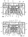
- the device shown in Figures 1-5 is an air operated double diaphragm pump. Construction is of thermoplastic materials although the pump could be constructed of other materials.
- the wet ends (contacting pumped material) are constructed of polypropylene for general chemical uses or conductive acetal for applications when pumping flammable materials and solvents.
- the device incorporates techniques to reduce assembly time and eliminate assembly errors.
- the design also reduces the number of parts as well as providing unique features such as mounting flexibility and multiple plumbing combinations.
- the check valves allow the pump to be mounted in any position without affecting its ability to prime or pump.
- the design allows assembly in one direction rather than continually reorientating the pump to perform various assembly operations.
- An air motor housing consists of two shells. All of the air motor valving is installed inside the shells. The structural ribbing in the cavity provides sufficient internal baffling to eliminate the need for an external muffler.
- the exhaust port is also threaded to provide means to pipe exhaust air to a remote location.
- the air motor also extends beyond the fluid cap housings to allow cover plates to be attached inside the ends of the motor housings. The plates cover the exposed fasteners, provide a "clean" look to the pump and displays labelled porting for fluid and air connections.
- the fluid and air connections for this design differ from the conventional diaphragm pump design in that the connections are made on the end of the pump (in-line with the diaphragm centreline as opposed to perpendicular).
- Fluid connections may be made on either end.
- the air is provided to air inlet 113 on one end only. This allows the pump to be installed in any axis in line with the plumbing system. It is particularly useful for applications where the pump must be inserted into a shaft or hole where fluid and air supply hoses cannot extend beyond the pump outside diameter.
- the pump is operated by supplying compressed air or gas to the air motor inlet port.
- the valving in the air motor senses position of the diaphragms and alternately pressurises and exhausts the appropriate air chamber to cause the diaphragms to oscillate.
- the two diaphragms are connected by a rod so the two diaphragms move together resulting in a relatively constant fluid flow output.
- the motor consists of a spool valve 101 and pilot valve 102.
- the spool valve 101 connects air supply and exhaust ports to the appropriate diaphragm air chambers 103 and 104.
- the spool valve is actuated by supplying air pressure to each end of the spool valve 101.
- Supply air pressure is applied via air inlet 115 to the small end 116 of the spool valve to hold the valve in one position (to the right).
- a pilot signal is applied to the large end 117. Since the area of the large end is approximately twice the area of the small end, applying equal air pressure to both ends will cause the spool to shift to the left as viewed in Figure 1.
- the pilot valve 102 is a three way valve with an output port (not shown) connected to the spool valve 101. This provides an on or off pilot signal to the spool valve 101 depending on the pilot valve spool position.
- the diaphragm backup washer 105 contacts the ends of the pilot valve which project into the chambers 103, 104 and moves it to either pressurise or exhaust the large end 117 of the spool 101 valve.
- the diaphragms 106, 107 reverses direction to begin another pumping stroke.
- the pumping section consists of two pumping chambers 108 and 109. The chambers are separated from air chambers 103 and 104 by a flexible membrane 106 and 107. The membranes or diaphragms are connected to each other by a diaphragm rod 110.
- material flow into and out of the pumping chambers 108, 109 is controlled by two one-way check valves positioned in each fluid chamber housing.
- One check 112A or 112B allows material to flow into the chamber (inlet check) on the suction stroke while the other check 114A or 114B (outlet check) prevents material from flowing back into the chamber from the pump outlet.
- the inlet check 112A or 112B closes and the outlet check 114A or 114B opens allowing material to flow out of the pumping chamber.
- the design allows customer selected inlet/outlet positions. There are two inlets 120A and 120B and two outlets 121A and 121B available. One each (inlet and outlet) or all may be used depending on the application.
- the pump may also be converted to a dual inlet/outlet configuration by substituting a solid rod for one or both manifold tubes 123A or 123B. This allows the pump to be configured as a single inlet/dual outlet; dual inlet/single outlet or dual inlet/dual outlet. This allows the pump to be used as two single acting pumps to pump two different materials or mix two different materials, etc.
- Compressed gas is supplied to port 113 which pressurises chamber 126.
- the pressure acts on the small diameter 116 of spool 101 forcing it to the right as shown in Figure 2.
- the gas also pressurises longitudinal port 127, cross port 128, and chamber port 129.
- Air chamber 103 is pressurised through chamber port 129.
- Air chamber 104 is exhausted to atmosphere through longitudinal exhaust port 130 and exhaust port 31.
- Pilot valve piston 102 is shown to its extreme right position. It is held in position by the air pressure in chamber 103 acting on the full diameter of the pilot piston 102.
- Cross exhaust port 133 from the large end of spool 101 is connected to atmosphere through exhaust port 132.
- diaphragm 106 Compressed gas or air acts on diaphragm 106 (see Figure 3) forcing it to the left since the air side of diaphragm 107 is connected to exhaust as shown in Figure 3.
- diaphragm 106 moves, it displaces fluid from pumping chamber 108 through check valve 112A into manifold outlet 121A.
- Check valve 114A is closed when fluid forces disc 134A against the seat as fluid tries to flow through the check. Since the two diaphragms 106, 107 move together, diaphragm 107 is creating a vacuum in chamber 109. Fluid flows from the pump material inlet 120B through inlet check 112B into pump chamber 109. The outlet check 114B closes to prevent material from flowing back into the pump chamber from the material outlet 121B.
- backup washer 135 ( Figure 5) contacts the extension of pilot valve 102 and pushes it to the position shown in Figure 5.
- exhaust port 132 is closed, ports 136 and 137 are connected.
- Port 136 is connected to the input supply air. This allows supply air to flow to chamber 138.
- the pressure acts on the large diameter 117 of spool 101 forcing it to the left.
- Diaphragm air chamber 104 is pressurised through port 140. Air pressure acting on diaphragm 107 causes the diaphragms to switch direction which reverses the action from left to right taking place within the pumping chambers as described above.
- backup washer 105 pushes pilot valve piston 102 to the right side position shown in Figure 2. This causes the spool valve 101 to shift back to the right as shown in Figure 2 to being a new cycle.
- Figures 4A and 4B are an exploded view of the pump. Assembly begins by placing six nuts 1 into an assembly fixture (not shown). O-rings 2 are placed on check valve cartridges 3 (four required). The cartridges are made up of seat 7, disc 8 and spring stop 9. The spring stop 9 is held in seat 7 through an interference fit. The cartridges 3 are inserted into fluid cap 4. Alignment pins on the seats assure correct orientation. Manifolds 6 are placed over the cartridges and fluid cap. Frictional fit between the O-rings, manifold and fluid cap retains the parts and allows the assembly to be placed into the assembly fixture with the manifolds locating inside the fixture.
- the diaphragm assembly is made up of a diaphragm nut 10, diaphragm 106, 107 and backup washer 105, 135. Two diaphragm assemblies are required.
- the diaphragm 16 assembly is placed into groove 13 of fluid cap 4. This groove is identical to the groove on fluid cap 14.
- O-ring 15 is placed in a groove on the O.D. of diaphragm assembly 16.
- a U-cup 17 is inserted lips first into the centre bore of the air cap 35. Air cap 35 is then placed over fluid cap 4. Diaphragm rod 110 is inserted through the U-cup 17 and threaded onto the threaded stud on diaphragm assembly 16. Rod 110 is next bottomed out against the assembly. Bushing 20 is slid over rod 19. Seal 21 is inserted into groove of air cap 18. O-rings 22, 23, and U-cup 24 are installed on spool 101 and O-rings 26 (four required) are installed on pilot rod 102.
- valve block assembly continues by inserting spool 101 into valve block 28 and pilot rod 102 into minor valve block 29.
- Gasket 30 is installed on valve block 28. Mating surfaces of minor valve block 29 and valve block 28 are aligned and the parts pressed together.
- O-rings 31 and 32 are installed to valve block 28, and O-rings 33 and 34 installed to minor valve block 29.
- the valve block assembly is inserted into the mating bores of air cap 35. U-cup 51 is then inserted lips first into air cap 18. Air cap 35 is then set in place on air cap 18.
- Alignment pins 37 assure proper orientation and alignment of caps and valve block assembly.
- O-rings 50 are installed into air cap 18. Place O-ring 38 into groove of air cap 18. The groove is identical to groove 39 shown in air cap 35. Thread and bottom out diaphragm assembly 40 onto diaphragm rod 19. Continuing, place fluid cap 14 over diaphragm assembly.
- the next step is to install O-rings 41 onto manifold tubes 123A, 123B, and insert the tubes 123A, 123B through the notches 43 in fluid cap 14 and into manifolds 6.
Landscapes
- Engineering & Computer Science (AREA)
- Mechanical Engineering (AREA)
- General Engineering & Computer Science (AREA)
- Reciprocating Pumps (AREA)
Applications Claiming Priority (2)
| Application Number | Priority Date | Filing Date | Title |
|---|---|---|---|
| US61883 | 1993-05-14 | ||
| US08/061,883 US5391060A (en) | 1993-05-14 | 1993-05-14 | Air operated double diaphragm pump |
Publications (2)
| Publication Number | Publication Date |
|---|---|
| EP0624729A1 true EP0624729A1 (fr) | 1994-11-17 |
| EP0624729B1 EP0624729B1 (fr) | 1996-12-27 |
Family
ID=22038760
Family Applications (1)
| Application Number | Title | Priority Date | Filing Date |
|---|---|---|---|
| EP94303411A Expired - Lifetime EP0624729B1 (fr) | 1993-05-14 | 1994-05-12 | Pompe double-diaphragme actionnée par air |
Country Status (5)
| Country | Link |
|---|---|
| US (1) | US5391060A (fr) |
| EP (1) | EP0624729B1 (fr) |
| JP (1) | JPH06346857A (fr) |
| CA (1) | CA2122673C (fr) |
| DE (1) | DE69401235T2 (fr) |
Cited By (5)
| Publication number | Priority date | Publication date | Assignee | Title |
|---|---|---|---|---|
| EP0824192A3 (fr) * | 1996-08-12 | 1999-09-22 | Smc Corporation | Pompe double-diaphragme actionnée par fluide |
| EP0895567A4 (fr) * | 1996-03-11 | 2000-11-15 | Desalco Limited | Dispositif lineaire formant distributeur a tiroir cylindrique pour un systeme d'echangeur |
| WO2008101517A1 (fr) * | 2007-02-22 | 2008-08-28 | Gardner Denver Thomas Gmbh | Pompe à connexions multiples comprenant une soupape de réduction de bruit et couplage de palier |
| WO2010056173A1 (fr) * | 2008-11-17 | 2010-05-20 | Tapflo Ab | Procédé et dispositif pour une pompe |
| CN114320856A (zh) * | 2020-09-29 | 2022-04-12 | 深圳国技仪器有限公司 | 大气采样设备用双头多功能微型隔膜泵 |
Families Citing this family (35)
| Publication number | Priority date | Publication date | Assignee | Title |
|---|---|---|---|---|
| CN1165699C (zh) * | 1996-04-12 | 2004-09-08 | 格雷科有限公司 | 单向阀 |
| US5758563A (en) * | 1996-10-23 | 1998-06-02 | Holcom Co. | Fluid driven reciprocating pump |
| DE19738779C2 (de) * | 1997-09-04 | 2003-06-12 | Almatec Maschb Gmbh | Umsteuersystem für eine druckgetriebene Membranpumpe |
| WO1999037921A1 (fr) * | 1998-01-26 | 1999-07-29 | Massachusetts Institute Of Technology | Pompe a soufflets a actionneur contractile |
| US6168394B1 (en) * | 1999-06-18 | 2001-01-02 | Wilden Pump & Engineering Co. | Air driven double diaphragm pump |
| US6190136B1 (en) | 1999-08-30 | 2001-02-20 | Ingersoll-Rand Company | Diaphragm failure sensing apparatus and diaphragm pumps incorporating same |
| US6280149B1 (en) | 1999-10-28 | 2001-08-28 | Ingersoll-Rand Company | Active feedback apparatus and air driven diaphragm pumps incorporating same |
| US6746637B1 (en) | 1999-11-15 | 2004-06-08 | Westinghouse Air Brake Technologies Corporation | Process for making chemical resistant pump diaphragm |
| JP2004036577A (ja) * | 2002-07-05 | 2004-02-05 | Toshiba Tec Corp | エアーポンプ |
| US6901960B2 (en) * | 2002-09-06 | 2005-06-07 | Ingersoll-Rand Company | Double diaphragm pump including spool valve air motor |
| US6824364B2 (en) | 2002-09-20 | 2004-11-30 | Rimcraft Technologies, Inc. | Master/slave pump assembly employing diaphragm pump |
| US6865981B2 (en) * | 2003-03-11 | 2005-03-15 | Ingersoll-Rand Company | Method of producing a pump |
| US6883417B2 (en) * | 2003-03-19 | 2005-04-26 | Ingersoll-Rand Company | Connecting configuration for a diaphragm in a diaphragm pump |
| US7025578B2 (en) * | 2003-05-07 | 2006-04-11 | Ingersoll-Rand Company | Pump having air valve with integral pilot |
| US20050012334A1 (en) * | 2003-07-17 | 2005-01-20 | Ingersoll-Rand Company | Method of manufacturing flow connectors having overmolded inserts and product produced thereby |
| US20050011575A1 (en) * | 2003-07-17 | 2005-01-20 | Ingersoll-Rand Company | Method of manufacturing flow connectors and product produced thereby |
| US7367785B2 (en) * | 2004-03-19 | 2008-05-06 | Ingersoll-Rand Company | Reduced icing valves and gas-driven motor and reciprocating pump incorporating same |
| US7063517B2 (en) | 2004-06-16 | 2006-06-20 | Ingersoll-Rand Company | Valve apparatus and pneumatically driven diaphragm pump incorporating same |
| US8197231B2 (en) | 2005-07-13 | 2012-06-12 | Purity Solutions Llc | Diaphragm pump and related methods |
| US7399168B1 (en) * | 2005-12-19 | 2008-07-15 | Wilden Pump And Engineering Llc | Air driven diaphragm pump |
| GB0712739D0 (en) | 2007-07-02 | 2007-08-08 | Smith & Nephew | Apparatus |
| US8167586B2 (en) * | 2008-08-22 | 2012-05-01 | Ingersoll-Rand Company | Valve assembly with low resistance pilot shifting |
| KR101718561B1 (ko) | 2009-04-23 | 2017-03-21 | 그라코 미네소타 인크. | 오버몰드 다이아프램 펌프 |
| US20110033316A1 (en) * | 2009-08-05 | 2011-02-10 | Tim Marchbanks | System for controlling the stroke of an air-operated double diaphragm pump |
| US9610392B2 (en) | 2012-06-08 | 2017-04-04 | Fresenius Medical Care Holdings, Inc. | Medical fluid cassettes and related systems and methods |
| US9714665B2 (en) | 2013-12-13 | 2017-07-25 | Asia Connection LLC | Pool pump with multiple outlets |
| CN106030109B (zh) * | 2014-03-26 | 2020-10-02 | 乔圣有限公司 | 加压流体驱动的隔膜泵组件 |
| EP3155263B1 (fr) * | 2014-06-16 | 2021-03-17 | Flow Control LLC. | Pompe à membrane utilisant des soupapes à bec de canard, des orifices multi-directionnels et une connectivité électrique flexible |
| MY184678A (en) * | 2015-11-23 | 2021-04-16 | Bee Cheong Teh | Air-operated double diaphragm pump |
| US10527033B2 (en) * | 2017-11-09 | 2020-01-07 | Ingersoll-Rand Company | Abrasion and puncture resistant diaphragm |
| JP6832888B2 (ja) * | 2018-05-24 | 2021-02-24 | 株式会社ヤマダコーポレーション | ダイヤフラムポンプ |
| US11471660B2 (en) * | 2018-10-25 | 2022-10-18 | Covidien Lp | Vacuum driven suction and irrigation system |
| JP6975468B2 (ja) * | 2019-02-20 | 2021-12-01 | 株式会社ワイ・テイ・エス | ダイアフラムポンプおよびダイアフラムポンプの組立方法 |
| US11746771B2 (en) * | 2021-04-16 | 2023-09-05 | Teryair Equipment Pvt. Ltd. | Actuator valve of an air operated double diaphragm pump |
| USD1099288S1 (en) | 2022-03-23 | 2025-10-21 | T.J. Smith And Nephew, Limited | Device for applying negative pressure to a wound |
Citations (3)
| Publication number | Priority date | Publication date | Assignee | Title |
|---|---|---|---|---|
| GB2060086A (en) * | 1979-09-21 | 1981-04-29 | Coca Cola Co | Reciprocating Pump Apparatus and Reversing Mechanism Therefor |
| EP0298615A2 (fr) * | 1987-06-11 | 1989-01-11 | Flotronic Controls Limited | Double pompe à membrane |
| WO1992019868A1 (fr) * | 1991-05-02 | 1992-11-12 | The Aro Corporation | Pompe a diaphragmes et a pistons |
Family Cites Families (11)
| Publication number | Priority date | Publication date | Assignee | Title |
|---|---|---|---|---|
| US4019838A (en) * | 1975-09-03 | 1977-04-26 | Fluck Henry T | Air pressure-actuated double-acting diaphragm pump with means to produce a selected start-up position |
| US4008984A (en) * | 1975-10-23 | 1977-02-22 | Scholle William R | Pump apparatus |
| US4386888A (en) * | 1980-09-29 | 1983-06-07 | Mccann's Engineering And Manufacturing Company | Double diaphragm operated reversing valve pump |
| US4682937A (en) * | 1981-11-12 | 1987-07-28 | The Coca-Cola Company | Double-acting diaphragm pump and reversing mechanism therefor |
| US4549467A (en) * | 1983-08-03 | 1985-10-29 | Wilden Pump & Engineering Co. | Actuator valve |
| US4540349A (en) * | 1984-05-16 | 1985-09-10 | Du Benjamin R | Air driven pump |
| US4597721A (en) * | 1985-10-04 | 1986-07-01 | Valco Cincinnati, Inc. | Double acting diaphragm pump with improved disassembly means |
| US5213485A (en) * | 1989-03-10 | 1993-05-25 | Wilden James K | Air driven double diaphragm pump |
| US5108270A (en) * | 1990-07-27 | 1992-04-28 | The Aro Corporation | Conductive plastic fluid handling equipment |
| US5195878A (en) * | 1991-05-20 | 1993-03-23 | Hytec Flow Systems | Air-operated high-temperature corrosive liquid pump |
| US5240390A (en) * | 1992-03-27 | 1993-08-31 | Graco Inc. | Air valve actuator for reciprocable machine |
-
1993
- 1993-05-14 US US08/061,883 patent/US5391060A/en not_active Expired - Lifetime
-
1994
- 1994-05-02 CA CA002122673A patent/CA2122673C/fr not_active Expired - Fee Related
- 1994-05-12 EP EP94303411A patent/EP0624729B1/fr not_active Expired - Lifetime
- 1994-05-12 DE DE69401235T patent/DE69401235T2/de not_active Expired - Fee Related
- 1994-05-16 JP JP6100372A patent/JPH06346857A/ja active Pending
Patent Citations (3)
| Publication number | Priority date | Publication date | Assignee | Title |
|---|---|---|---|---|
| GB2060086A (en) * | 1979-09-21 | 1981-04-29 | Coca Cola Co | Reciprocating Pump Apparatus and Reversing Mechanism Therefor |
| EP0298615A2 (fr) * | 1987-06-11 | 1989-01-11 | Flotronic Controls Limited | Double pompe à membrane |
| WO1992019868A1 (fr) * | 1991-05-02 | 1992-11-12 | The Aro Corporation | Pompe a diaphragmes et a pistons |
Cited By (5)
| Publication number | Priority date | Publication date | Assignee | Title |
|---|---|---|---|---|
| EP0895567A4 (fr) * | 1996-03-11 | 2000-11-15 | Desalco Limited | Dispositif lineaire formant distributeur a tiroir cylindrique pour un systeme d'echangeur |
| EP0824192A3 (fr) * | 1996-08-12 | 1999-09-22 | Smc Corporation | Pompe double-diaphragme actionnée par fluide |
| WO2008101517A1 (fr) * | 2007-02-22 | 2008-08-28 | Gardner Denver Thomas Gmbh | Pompe à connexions multiples comprenant une soupape de réduction de bruit et couplage de palier |
| WO2010056173A1 (fr) * | 2008-11-17 | 2010-05-20 | Tapflo Ab | Procédé et dispositif pour une pompe |
| CN114320856A (zh) * | 2020-09-29 | 2022-04-12 | 深圳国技仪器有限公司 | 大气采样设备用双头多功能微型隔膜泵 |
Also Published As
| Publication number | Publication date |
|---|---|
| CA2122673A1 (fr) | 1994-11-15 |
| CA2122673C (fr) | 2003-02-04 |
| US5391060A (en) | 1995-02-21 |
| EP0624729B1 (fr) | 1996-12-27 |
| JPH06346857A (ja) | 1994-12-20 |
| DE69401235T2 (de) | 1998-01-15 |
| DE69401235D1 (de) | 1997-02-06 |
Similar Documents
| Publication | Publication Date | Title |
|---|---|---|
| EP0624729B1 (fr) | Pompe double-diaphragme actionnée par air | |
| US6644353B1 (en) | Modular surface mount manifold | |
| US4247264A (en) | Air driven diaphragm pump | |
| US7686041B2 (en) | Modular surface mount manifold assemblies | |
| US6629546B2 (en) | Modular surface mount manifold assemblies | |
| US5228839A (en) | Multistage ejector pump | |
| US7399168B1 (en) | Air driven diaphragm pump | |
| US6901961B2 (en) | Double diaphragm pump having a spool valve | |
| US7036528B2 (en) | Modular surface mount manifold assemblies | |
| JPS5979080A (ja) | 流体駆動往復ポンプ | |
| US5711658A (en) | Diaphragm pump with improved flow manifolds | |
| EP0134185B1 (fr) | Distributeur modulaire | |
| EP0703392B1 (fr) | Garniture pour un assemblage de soupape | |
| EP1607632B1 (fr) | Dispositif à soupape et pompe à diaphragme actionné de manière pneumatique avec un tel dispositif | |
| EP1078184A2 (fr) | Assemblages distributeurs montes sur surface modulaire | |
| GB2228772A (en) | Pump to drum mounting arrangement | |
| US5334003A (en) | Air valving mechanism, in combination with a double diaphragm pump subassembly | |
| US4422835A (en) | Fluid operated diaphragm pump with fluid timing control and control circuit manifold mounted on pump body | |
| US5016522A (en) | Multi-stage air pressure cylinder | |
| EP0018143B1 (fr) | Pompe à diaphragme entraînée par air | |
| US5851109A (en) | Spacer and shim assembly for fluid powered diaphragm pumps | |
| EP1134469A2 (fr) | Distributeur à vanne avec fixation de chapeaux | |
| CN224189468U (zh) | 一种泄漏诊断模块 | |
| JP2679935B2 (ja) | 電磁弁マニホールド | |
| JPH0875071A (ja) | 給排ポートのカートリッジ式ポート継手の固定構造 |
Legal Events
| Date | Code | Title | Description |
|---|---|---|---|
| PUAI | Public reference made under article 153(3) epc to a published international application that has entered the european phase |
Free format text: ORIGINAL CODE: 0009012 |
|
| AK | Designated contracting states |
Kind code of ref document: A1 Designated state(s): DE FR GB IT SE |
|
| 17P | Request for examination filed |
Effective date: 19950513 |
|
| 17Q | First examination report despatched |
Effective date: 19951127 |
|
| GRAG | Despatch of communication of intention to grant |
Free format text: ORIGINAL CODE: EPIDOS AGRA |
|
| GRAH | Despatch of communication of intention to grant a patent |
Free format text: ORIGINAL CODE: EPIDOS IGRA |
|
| GRAH | Despatch of communication of intention to grant a patent |
Free format text: ORIGINAL CODE: EPIDOS IGRA |
|
| GRAA | (expected) grant |
Free format text: ORIGINAL CODE: 0009210 |
|
| AK | Designated contracting states |
Kind code of ref document: B1 Designated state(s): DE FR GB IT SE |
|
| REG | Reference to a national code |
Ref country code: GB Ref legal event code: 732E |
|
| ITPR | It: changes in ownership of a european patent |
Owner name: CESSIONE EPO REG. 20;INGERSOLL-RAND COMPANY |
|
| REF | Corresponds to: |
Ref document number: 69401235 Country of ref document: DE Date of ref document: 19970206 |
|
| ITF | It: translation for a ep patent filed | ||
| RAP2 | Party data changed (patent owner data changed or rights of a patent transferred) |
Owner name: INGERSOLL-RAND COMPANY |
|
| PG25 | Lapsed in a contracting state [announced via postgrant information from national office to epo] |
Ref country code: SE Effective date: 19970327 |
|
| ET | Fr: translation filed | ||
| PLBE | No opposition filed within time limit |
Free format text: ORIGINAL CODE: 0009261 |
|
| STAA | Information on the status of an ep patent application or granted ep patent |
Free format text: STATUS: NO OPPOSITION FILED WITHIN TIME LIMIT |
|
| 26N | No opposition filed | ||
| REG | Reference to a national code |
Ref country code: GB Ref legal event code: IF02 |
|
| PGFP | Annual fee paid to national office [announced via postgrant information from national office to epo] |
Ref country code: IT Payment date: 20080529 Year of fee payment: 15 |
|
| PGFP | Annual fee paid to national office [announced via postgrant information from national office to epo] |
Ref country code: DE Payment date: 20080630 Year of fee payment: 15 |
|
| PGFP | Annual fee paid to national office [announced via postgrant information from national office to epo] |
Ref country code: GB Payment date: 20080529 Year of fee payment: 15 |
|
| GBPC | Gb: european patent ceased through non-payment of renewal fee |
Effective date: 20090512 |
|
| REG | Reference to a national code |
Ref country code: FR Ref legal event code: ST Effective date: 20100129 |
|
| PG25 | Lapsed in a contracting state [announced via postgrant information from national office to epo] |
Ref country code: FR Free format text: LAPSE BECAUSE OF NON-PAYMENT OF DUE FEES Effective date: 20090602 |
|
| PGFP | Annual fee paid to national office [announced via postgrant information from national office to epo] |
Ref country code: FR Payment date: 20080519 Year of fee payment: 15 |
|
| PG25 | Lapsed in a contracting state [announced via postgrant information from national office to epo] |
Ref country code: GB Free format text: LAPSE BECAUSE OF NON-PAYMENT OF DUE FEES Effective date: 20090512 |
|
| PG25 | Lapsed in a contracting state [announced via postgrant information from national office to epo] |
Ref country code: DE Free format text: LAPSE BECAUSE OF NON-PAYMENT OF DUE FEES Effective date: 20091201 |
|
| PG25 | Lapsed in a contracting state [announced via postgrant information from national office to epo] |
Ref country code: IT Free format text: LAPSE BECAUSE OF NON-PAYMENT OF DUE FEES Effective date: 20090512 |