EP1607632B1 - Dispositif à soupape et pompe à diaphragme actionné de manière pneumatique avec un tel dispositif - Google Patents
Dispositif à soupape et pompe à diaphragme actionné de manière pneumatique avec un tel dispositif Download PDFInfo
- Publication number
- EP1607632B1 EP1607632B1 EP20050010865 EP05010865A EP1607632B1 EP 1607632 B1 EP1607632 B1 EP 1607632B1 EP 20050010865 EP20050010865 EP 20050010865 EP 05010865 A EP05010865 A EP 05010865A EP 1607632 B1 EP1607632 B1 EP 1607632B1
- Authority
- EP
- European Patent Office
- Prior art keywords
- actuator
- diaphragms
- valve
- diaphragm pump
- chamber
- Prior art date
- Legal status (The legal status is an assumption and is not a legal conclusion. Google has not performed a legal analysis and makes no representation as to the accuracy of the status listed.)
- Expired - Lifetime
Links
- 239000012530 fluid Substances 0.000 claims description 24
- 239000000463 material Substances 0.000 claims description 13
- 230000000694 effects Effects 0.000 claims description 5
- 229920002725 thermoplastic elastomer Polymers 0.000 claims description 4
- 229920002803 thermoplastic polyurethane Polymers 0.000 claims description 4
- 239000011324 bead Substances 0.000 claims description 3
- 238000005086 pumping Methods 0.000 claims description 3
- 238000003780 insertion Methods 0.000 claims 1
- 230000037431 insertion Effects 0.000 claims 1
- 230000004048 modification Effects 0.000 description 3
- 238000012986 modification Methods 0.000 description 3
- 238000007789 sealing Methods 0.000 description 3
- 238000010276 construction Methods 0.000 description 2
- 238000002347 injection Methods 0.000 description 2
- 239000007924 injection Substances 0.000 description 2
- 238000001746 injection moulding Methods 0.000 description 2
- 239000000126 substance Substances 0.000 description 2
- 230000004888 barrier function Effects 0.000 description 1
- 238000013037 co-molding Methods 0.000 description 1
- 239000002131 composite material Substances 0.000 description 1
- 238000011109 contamination Methods 0.000 description 1
- 239000013536 elastomeric material Substances 0.000 description 1
- 108010036050 human cationic antimicrobial protein 57 Proteins 0.000 description 1
- 239000000314 lubricant Substances 0.000 description 1
- 238000004519 manufacturing process Methods 0.000 description 1
- 239000007769 metal material Substances 0.000 description 1
- 229920000642 polymer Polymers 0.000 description 1
- 229920002635 polyurethane Polymers 0.000 description 1
- 239000004814 polyurethane Substances 0.000 description 1
- 229920001187 thermosetting polymer Polymers 0.000 description 1
Images



Classifications
-
- F—MECHANICAL ENGINEERING; LIGHTING; HEATING; WEAPONS; BLASTING
- F04—POSITIVE - DISPLACEMENT MACHINES FOR LIQUIDS; PUMPS FOR LIQUIDS OR ELASTIC FLUIDS
- F04B—POSITIVE-DISPLACEMENT MACHINES FOR LIQUIDS; PUMPS
- F04B43/00—Machines, pumps, or pumping installations having flexible working members
- F04B43/02—Machines, pumps, or pumping installations having flexible working members having plate-like flexible members, e.g. diaphragms
- F04B43/06—Pumps having fluid drive
- F04B43/073—Pumps having fluid drive the actuating fluid being controlled by at least one valve
- F04B43/0733—Pumps having fluid drive the actuating fluid being controlled by at least one valve with fluid-actuated pump inlet or outlet valves; with two or more pumping chambers in series
-
- F—MECHANICAL ENGINEERING; LIGHTING; HEATING; WEAPONS; BLASTING
- F04—POSITIVE - DISPLACEMENT MACHINES FOR LIQUIDS; PUMPS FOR LIQUIDS OR ELASTIC FLUIDS
- F04B—POSITIVE-DISPLACEMENT MACHINES FOR LIQUIDS; PUMPS
- F04B43/00—Machines, pumps, or pumping installations having flexible working members
- F04B43/02—Machines, pumps, or pumping installations having flexible working members having plate-like flexible members, e.g. diaphragms
- F04B43/06—Pumps having fluid drive
- F04B43/073—Pumps having fluid drive the actuating fluid being controlled by at least one valve
- F04B43/0736—Pumps having fluid drive the actuating fluid being controlled by at least one valve with two or more pumping chambers in parallel
-
- Y—GENERAL TAGGING OF NEW TECHNOLOGICAL DEVELOPMENTS; GENERAL TAGGING OF CROSS-SECTIONAL TECHNOLOGIES SPANNING OVER SEVERAL SECTIONS OF THE IPC; TECHNICAL SUBJECTS COVERED BY FORMER USPC CROSS-REFERENCE ART COLLECTIONS [XRACs] AND DIGESTS
- Y10—TECHNICAL SUBJECTS COVERED BY FORMER USPC
- Y10T—TECHNICAL SUBJECTS COVERED BY FORMER US CLASSIFICATION
- Y10T137/00—Fluid handling
- Y10T137/8593—Systems
- Y10T137/86493—Multi-way valve unit
- Y10T137/86574—Supply and exhaust
- Y10T137/86622—Motor-operated
- Y10T137/8663—Fluid motor
Definitions
- This invention relates generally to a pneumatically driven double diaphragm pump.
- Spool valves are used and known in the art as directional control valves for changing the direction of a motive fluid to and from pistons or diaphragms located within cylinders or other chambers, respectively.
- a conventional spool valve comprises a valve body and a sliding spool actuator which, upon shifting therein, alternately defines flow passages within the valve body to a supply pressure or an exhaust port causing a cylinder's piston rod or chamber's diaphragm to be moved and work performed.
- directional control valves have been used as the major distribution valve for providing a pressurized motive fluid, e.g., pressurized air, to chambers associated with a double acting diaphragm pump.
- a pressurized motive fluid e.g., pressurized air
- Examples are shown in commonly assigned U.S. Patent Nos. 4,854,832 , 5,391,060 , and 6,722,256 , the disclosures of which are hereby referenced as related technical teaching.
- U.S. Patent No 5,391,060 a spool valve is disposed in a valve body and connects air supply and exhaust ports to appropriate diaphragm air chambers via O-rings located on the spool valve.
- 4,854,832 and 6,722,256 include a spool valve having a spool actuator that has "U"-cup seals and receives a sliding "D" valve that establishes fluid interconnections upon shifting of the spool valve.
- the spool actuators are differential actuators having at least two diameters to respond to a differential pressure in order to prevent stalling of the valve.
- seals used on such spool actuators such as the "O"-ring and "U"-cup seals described above, however, require excellent inner surface finishes on the valve body bores.
- a lubricant is also generally used either in the bore or in the seal itself to help reduce friction in moving the piston.
- many pumping applications require a lubrication-free environment to avoid contamination of the media being handled.
- Double diaphragm pumps are known from GB-A-2 140 097 ; US-A-4 496 294 ; and US-A-4 549 467 .
- US-A-6 722 256 is considered to represent the closest prior art, but fails to disclose a valve apparatus being provided with first and second diaphragms which define wall portions of the valve apparatus.
- the embodiments disclose a valve apparatus, and pneumatically driven diaphragm pump incorporating the same, having a valve body having a longitudinal axis and an actuator having an axis with a first end and a second end.
- the first and second ends have first and second diaphragms, respectively, disposed thereon and located transversely to the axis of the actuator.
- the first and second diaphragms Upon inserting the actuator into the valve body, the first and second diaphragms define wall portions of first and second chambers at the first and second ends of the axis of the actuator, respectively, and a chamber defined between the diaphragms.
- diaphragm means a flexible barrier that divides two fluid containing chambers or compartments.
- FIG. 1 shown in FIG. 1 is a valve apparatus according to the present invention comprising an actuator 42 disposed within a chamber 59 located in a valve block or body 2.
- Actuator 42 is a generally cylindrical spool member having a first end surface 55 and a second end surface 80 positioned within chamber 59 which is connected to a motive fluid such as compressed air via fluid pressure inlet 86.
- Actuator 42 has a substantially constant diameter with annular rings 69 having outer diameters that are substantially the same as the inner diameter of chamber 59.
- An annular groove 68 is defined between annular rings 69 which receives a sliding valve insert 70 that extends through the wall of valve body 2 and slides against a valve plate 3 as shown.
- valve plate 3 and valve insert 70 are constructed of materials that are chemically inert and/or are internally lubricated to minimize chemical compatibility problems and reduce frictional loads, respectively, while also permitting the use of motive gas sources that are dirty.
- Chamber 59 is disposed between and coaxially aligned with a first chamber 58 and a second chamber 60.
- a first diaphragm 15 is attached to first end surface 55 of actuator 42 and disposed between first chamber 58 and chamber 59.
- a second diaphragm 16 is attached to second end surface 80 of actuator 42 and disposed between second chamber 60 and chamber 59.
- First and second chambers 58, 60 are alternately connected via first and second passages 56, 62 to a pneumatic pilot signal or to atmosphere to effect shifting of actuator 42 as described in detail below and may be accomplished via a separate mechanical or electrical shifting device.
- Exemplary shifting devices in this regard being conventional pilot valves that can be solenoid or mechanically activated trip rods to control pneumatic shifting logic, which are known in the art and therefore not described in detail.
- first diaphragm 15 and second diaphragm 16 are mechanically fastened to their respective ends of actuator 42 and clamped between chamber 59 and first and second chambers 58, 60, respectively. Clamping of the diaphragms in place may be accomplished by a first end cap 57 and a second end cap 61 which threadingly engage inner threads of valve body 2 preferably with sealing members 17 that engage the diaphragms as shown. Sealing members may be discrete elements as shown or may be integrally provided with the diaphragm members as described in detail further below.
- the diaphragms are manufactured from a flexible material, preferably, from an elastomeric material as is known to those skilled in the art.
- valve insert 70 is limited by the wall of valve body 2 to correspond with the range of motion of the travel of the actuator 42 in chamber 59.
- Valve plate 3 includes an exhaust aperture 35, a first aperture 34, and a second aperture 36 defined through its thickness. The relative spacing and positions between exhaust aperture 35, first aperture 34, and second aperture 36 are configured such that during operation of the device, first aperture 34 and second aperture 36 are alternately connected to exhaust aperture 35.
- supply fluid pressure inlet 86 is connected to chamber 59 and provides fluid pressure to first aperture 34 and second aperture 36 when these apertures are not in fluid connection with exhaust aperture 35. In this manner, actuator 42 slides valve insert 70 between a first position in which first aperture 34 is connected to supply air when second aperture 36 is connected to exhaust and a second position in which second aperture 36 is connected to supply air when first aperture 34 is connected to exhaust.
- the diaphragms are preferably of different diameters relative to one another with first diaphragm 15 having a smaller diameter than second diaphragm 16 as shown.
- first diaphragm 15 having a smaller diameter than second diaphragm 16 as shown.
- valve apparatus may be incorporated as the major valve construction that provides and exhausts motive gas, respectively, to and from an air motor such as those used in diaphragm pumps as described in detail below.
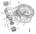
- FIGS. 2-7 Shown in FIGS. 2-7 is a center body section 125 of a conventional double diaphragm pump attached to a valve body 120 incorporating the valve construction of the present invention.
- the center body section 125 is shown in the partial perspective view of FIG. 2 attached to air caps 126 which define first and second opposed axially spaced pressure chambers 127 over which flexible pumping diaphragms (not shown) are mounted as is known in the art.
- FIG. 3 Shown in FIG. 3 is a side view of one of the air caps 126 having a pilot valve comprising a pilot piston 7 and an actuator pin 9 as is known in the art.
- pneumatic pilot signals accordingly shift an actuator 142 to shift within valve body 120 at the end of each pump stroke thereby alternating the exhausting and filling of the pressure chambers 127 via ports 128.
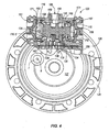
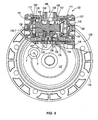
- valve apparatus Shown in the partial sectional views of FIGS. 4 and 6 is the sequential operation of a valve apparatus according to the present invention as configured for and used in conjunction with a pneumatic double diaphragm pump.
- the valve apparatus comprises an actuator 142 disposed within a chamber 159 located in a valve block or body 120 and connected to a motive fluid such as compressed air via fluid pressure inlet 186.
- a first diaphragm 115 and a second diaphragm 116 are integrally attached to actuator 142 and define a first chamber 158 and a second chamber 160, respectively, with the inner surfaces of first and second end caps 157, 161 inserted into valve body 120.
- O-ring seals 171 are provided as shown between the end caps 157, 161 and the inner surface of valve body 120 to effect sealing therebetween.
- First and second chambers 158, 160 are alternately connected via first and second passages 156, 162 to a pneumatic pilot signal or to atmosphere by pilot piston 7 to effect shifting of actuator 142.
- Chamber 159 is disposed between and coaxially aligned with first chamber 158 and second chamber 160.
- Actuator 142 is a generally cylindrical spool member having annular rings with projections 169 on both sides of a valve insert 170.
- Valve insert 170 slides against a valve plate 130 as shown and, preferably, is also engaged by an annular ring 168 provided on actuator 142.
- first diaphragm 115 and second diaphragm 116 are mechanically clamped between first and second end caps 157, 161 and valve body 120, respectively, by an integral bead portion 117 provided around the periphery of the diaphragms. In this manner, the circumferential bead portions seal chamber 159 from chambers 158 and 160.
- valve insert 170 is limited by the wall of valve body 120 to correspond with the range of motion of the travel of the actuator 142 in chamber 159.
- Valve plate 130 includes an exhaust aperture 135, a first aperture 134, and a second aperture 136 defined through its thickness. The relative spacing and positions between exhaust aperture 135, first aperture 134, and second aperture 136 are configured such that during operation of the device, first aperture 134 and second aperture 136 are alternately connected to exhaust aperture 135. When connected to exhaust aperture 135, first aperture 134 and second aperture 136 permit pressure chambers 127 to be exhausted via their respective ports 128.
- supply fluid pressure inlet 186 is connected to chamber 159 and provides fluid pressure to first aperture 134 and second aperture 136 when these apertures are not in fluid connection with exhaust aperture 135, thereby filling pressure chambers 127 via their respective ports 128.
- actuator 142 slides valve insert 170 between a first position in which first aperture 134 is connected to supply air when second aperture 136 is connected to exhaust and a second position in which second aperture 136 is connected to supply air when first aperture 134 is connected to exhaust.
- the diaphragms are preferably of different diameters relative to one another with first diaphragm 115 having a smaller diameter than second diaphragm 116 as shown.
- first diaphragm 115 having a smaller diameter than second diaphragm 116 as shown.
- actuator 142 may be manufactured from a flexible material, preferably, from a thermoplastic elastomer (TPE) or a thermoplastic urethane (TPU) material that is injection molded. As shown by the partial perspective and partial exploded view of FIG. 2 and the sectional views of FIGS. 4 and 6 , "core-outs" may be located longitudinally along the length of these components to facilitate injection molding of these parts.
- TPE thermoplastic elastomer
- TPU thermoplastic urethane
- An exemplary material that can be used to injection mold actuator 142 is a 4300 Series polyurethane material available from Parker Hannifin Corporation, Engineered Polymer Systems Division, Salt Lake City, UT.
- diaphragms 115, 116 may alternatively be provided as discrete components attached thereto to facilitate manufacture and/or use of different materials. It is also contemplated that co-molding may be used to integrally provide diaphragms on the actuator using different materials. The selection of different diaphragm materials may be for various reasons including, for example, variation of the flexure properties of the diaphragms.
- End caps 157, 161 and valve body 120 can be similarly be injected molded preferably using a thermoset plastic material or otherwise fabricated using a composite or metal material. As shown by the perspective exploded view on FIG. 2 and the sectional views of FIGS. 4 and 6 , "core-outs" may be located longitudinally along the length of these components to facilitate injection molding of these parts.
- valve plate 130 and valve insert 170 are constructed of materials that are chemically inert and/or are internally lubricated to minimize chemical compatibility problems and reduce frictional loads, respectively, while also permitting the use of motive gas sources that are dirty.
- valve apparatus may be incorporated into other pneumatic or hydraulic devices. It is understood, therefore, that the invention is capable of modification and therefore is not to be limited to the precise details set forth. Rather, various modifications may be made to the details of the specific disclosed embodiments within the scope of the claims.
Landscapes
- Engineering & Computer Science (AREA)
- Mechanical Engineering (AREA)
- General Engineering & Computer Science (AREA)
- Reciprocating Pumps (AREA)
- Multiple-Way Valves (AREA)
Claims (10)
- Pompe à double diaphragme entraînée de manière pneumatique comprenant :des première et deuxième chambres de pression espacées axialement opposées (127) sur lesquelles les diaphragmes de pompage flexibles sont montés ;un appareil de soupape comportant :(i) un corps de soupape (120) avec un axe longitudinal,(ii) un actionneur (142) comportant un axe avec une première extrémité (55) et une deuxième extrémité (80), les première et deuxième extrémités comportant des premier (115) et deuxième (116) diaphragmes, respectivement, fixés à celles-ci et placés transversalement par rapport à l'axe de l'actionneur (142),
dans lequel, sur insertion de l'actionneur (142) dans le corps de soupape (120), les premier et deuxième diaphragmes (115, 116) sont cramponnés au corps de soupape (120) autour de la périphérie des diaphragmes pour définir des parties de parois des première (158) et deuxième (160) chambres au niveau des première et deuxième extrémités de l'axe de l'actionneur, respectivement, et pour définir une troisième chambre (159) entre les diaphragmes (115, 116) et pour la rendre étanche par les diaphragmes (115, 116) par rapport aux première et deuxième chambres (158, 160), la troisième chambre pouvant être connectée à un fluide moteur via un orifice d'entrée de pression fluidique (186), et(iii) un mécanisme de soupape (170) pouvant coulisser entre une première position, dans laquelle la première chambre de pression est connectée à la troisième chambre de pression (159) lorsque la deuxième chambre de pression est connectée à l'échappement, et une deuxième position, dans laquelle la deuxième chambre de pression est connectée à la troisième chambre de pression (159) lorsque la première chambre de pression est connectée à l'échappement ; etun dispositif de décalage destiné à connecter alternativement les première (158) et deuxième (160) chambres à un signal pilote pneumatique ou à l'atmosphère pour effectuer le décalage de l'actionneur (142) pour faire coulisser le mécanisme de soupape (170) entre lesdites première et deuxième positions. - Pompe à double diaphragme selon la revendication 1, dans laquelle les diaphragmes (115, 116) sont solidaires avec les première et deuxième extrémités de l'actionneur (142).
- Pompe à double diaphragme selon la revendication 1 ou 2, dans laquelle le premier diaphragme (115) présente un premier diamètre et le deuxième diaphragme (116) présente un deuxième diamètre, le premier diamètre étant inférieur au deuxième diamètre.
- Pompe à double diaphragme selon l'une quelconque des revendications 1, 2 ou 3, comprenant de plus des capuchons d'extrémités (157, 161) configurés pour l'insertion dans le corps de soupape (120) le long de l'axe longitudinal pour définir des parties de parois des première et deuxième chambres (158, 160) opposées aux parties de parois définies par les premier et deuxième diaphragmes (115, 116).
- Pompe à double diaphragme selon la revendication 4, dans laquelle les diaphragmes (115, 116) comportent des parties de fixation solidaires comprenant un bourrelet (117) placé sur la périphérie des diaphragmes (115, 116) pour blocage entre le corps de soupape (120) et les capuchons d'extrémités (157, 161) insérés dans le corps de soupape.
- Pompe à double diaphragme selon l'une quelconque des revendications 1 à 5, dans laquelle l'actionneur comprend de plus des bagues annulaires (169) qui définissent une rainure annulaire entre elles.
- Pompe à double diaphragme selon la revendication 6, dans laquelle le mécanisme de soupape (170) est disposé dans la rainure annulaire, le mécanisme de soupape (170) étant actionné pour coulisser par un mouvement de va-et-vient de l'actionneur (142).
- Pompe à double diaphragme selon la revendication 7, dans laquelle l'actionneur comprend de plus une bague annulaire (168), disposée dans la rainure annulaire, qui se met en prise avec une fente placée dans le mécanisme de soupape (170).
- Pompe à double diaphragme selon l'une quelconque des revendications 1 à 8, dans laquelle l'actionneur (142) est fabriqué à partir de l'un parmi un élastomère thermoplastique (TPE) et un uréthane thermoplastique (TPU).
- Pompe à double diaphragme selon l'une quelconque des revendications 1 à 9, dans laquelle l'appareil de soupape comprend de plus une plaque porte-soupape (130) définissant des première (134) et deuxième (136) ouvertures et une ouverture d'échappement (135) ; dans laquelle les première et deuxième chambres de pression (127) communiquent avec la troisième chambre (159) par l'intermédiaire des première et deuxième ouvertures (134, 136) respectives ; dans laquelle le mécanisme de soupape (170) place alternativement l'une parmi les première (134) et deuxième (136) ouvertures en communication avec l'ouverture d'échappement (135) et l'autre parmi les première (134) et deuxième (136) ouvertures en communication avec la troisième chambre (159) en réponse au décalage de l'actionneur (142) ; et dans laquelle la plaque porte-soupape (130) et le mécanisme de soupape (170) sont construits de matériaux chimiquement inertes et lubrifiés de manière interne.
Priority Applications (1)
| Application Number | Priority Date | Filing Date | Title |
|---|---|---|---|
| EP20080167111 EP2012012B1 (fr) | 2004-06-16 | 2005-05-19 | Dispositif à soupape et pompe à diaphragme actionné de manière pneumatique avec un tel dispositif |
Applications Claiming Priority (2)
| Application Number | Priority Date | Filing Date | Title |
|---|---|---|---|
| US10/869,074 US7063517B2 (en) | 2004-06-16 | 2004-06-16 | Valve apparatus and pneumatically driven diaphragm pump incorporating same |
| US869074 | 2004-06-16 |
Related Child Applications (1)
| Application Number | Title | Priority Date | Filing Date |
|---|---|---|---|
| EP20080167111 Division EP2012012B1 (fr) | 2004-06-16 | 2005-05-19 | Dispositif à soupape et pompe à diaphragme actionné de manière pneumatique avec un tel dispositif |
Publications (2)
| Publication Number | Publication Date |
|---|---|
| EP1607632A1 EP1607632A1 (fr) | 2005-12-21 |
| EP1607632B1 true EP1607632B1 (fr) | 2009-02-18 |
Family
ID=34936695
Family Applications (2)
| Application Number | Title | Priority Date | Filing Date |
|---|---|---|---|
| EP20080167111 Ceased EP2012012B1 (fr) | 2004-06-16 | 2005-05-19 | Dispositif à soupape et pompe à diaphragme actionné de manière pneumatique avec un tel dispositif |
| EP20050010865 Expired - Lifetime EP1607632B1 (fr) | 2004-06-16 | 2005-05-19 | Dispositif à soupape et pompe à diaphragme actionné de manière pneumatique avec un tel dispositif |
Family Applications Before (1)
| Application Number | Title | Priority Date | Filing Date |
|---|---|---|---|
| EP20080167111 Ceased EP2012012B1 (fr) | 2004-06-16 | 2005-05-19 | Dispositif à soupape et pompe à diaphragme actionné de manière pneumatique avec un tel dispositif |
Country Status (4)
| Country | Link |
|---|---|
| US (1) | US7063517B2 (fr) |
| EP (2) | EP2012012B1 (fr) |
| CA (1) | CA2509996C (fr) |
| DE (2) | DE602005012756D1 (fr) |
Cited By (1)
| Publication number | Priority date | Publication date | Assignee | Title |
|---|---|---|---|---|
| TWI465641B (zh) * | 2011-01-20 | 2014-12-21 | Ulvac Kiko Inc | 活塞及真空泵浦 |
Families Citing this family (15)
| Publication number | Priority date | Publication date | Assignee | Title |
|---|---|---|---|---|
| US7587897B2 (en) * | 2007-04-10 | 2009-09-15 | Illinois Tool Works Inc. | Magnetically sequenced pneumatic motor |
| US7603854B2 (en) * | 2007-04-10 | 2009-10-20 | Illinois Tool Works Inc. | Pneumatically self-regulating valve |
| US7603855B2 (en) * | 2007-04-10 | 2009-10-20 | Illinois Tool Works Inc. | Valve with magnetic detents |
| US7665974B2 (en) * | 2007-05-02 | 2010-02-23 | Wanner Engineering, Inc. | Diaphragm pump position control with offset valve axis |
| JP5180165B2 (ja) * | 2009-08-19 | 2013-04-10 | 株式会社コガネイ | ダイヤフラム弁 |
| NO20093258A1 (no) * | 2009-10-30 | 2011-05-02 | Fmc Kongsberg Subsea As | Undervannspumpesystem |
| USD667465S1 (en) | 2011-09-23 | 2012-09-18 | Tuthill Corporation | Double diaphragm pump assembly |
| US9028224B2 (en) | 2011-09-23 | 2015-05-12 | Tuthill Corporation | Air operated double diaphragm pump |
| US9752566B2 (en) * | 2013-06-26 | 2017-09-05 | Ingersoll-Rand Company | Air mass control for diaphragm pumps |
| US20170138489A1 (en) * | 2013-11-08 | 2017-05-18 | Fisher Controls International Llc | Hard coated supply biased spool valves |
| USD923060S1 (en) * | 2018-08-09 | 2021-06-22 | Psg Germany Gmbh | Pump |
| CN110725792B (zh) * | 2019-10-14 | 2021-05-25 | 杭州盛维科技有限公司 | 一种液压隔膜泵及组合式筒状隔膜组件 |
| US11746771B2 (en) * | 2021-04-16 | 2023-09-05 | Teryair Equipment Pvt. Ltd. | Actuator valve of an air operated double diaphragm pump |
| US12326142B2 (en) | 2022-03-28 | 2025-06-10 | Wanner Engineering, Inc. | Diaphragm position control system |
| CN117386589A (zh) * | 2023-11-28 | 2024-01-12 | 宁波宇禾环保科技有限公司 | 一种膈膜泵 |
Family Cites Families (23)
| Publication number | Priority date | Publication date | Assignee | Title |
|---|---|---|---|---|
| US2860651A (en) * | 1955-01-24 | 1958-11-18 | Parker Hannifin Corp | Apparatus for controlling the emptying of tanks |
| US3365861A (en) * | 1964-04-09 | 1968-01-30 | Abcor Inc | Gas fractionating apparatus |
| US3762443A (en) * | 1967-09-19 | 1973-10-02 | Tektro Inc | Resilient fluid control valve |
| GB1291102A (en) * | 1969-01-21 | 1972-09-27 | Sperry Rand Ltd | Improvements in, or relating to, fluid flow control valves |
| US3652187A (en) * | 1970-10-29 | 1972-03-28 | Amicon Corp | Pump |
| US3773082A (en) * | 1971-01-05 | 1973-11-20 | Bio Logics Products | Fluid valve |
| US4303003A (en) * | 1977-05-25 | 1981-12-01 | Vapor Corporation | Switching valve |
| US4138089A (en) * | 1977-08-09 | 1979-02-06 | The United States Of America As Represented By The Secretary Of The Department Of Health, Education And Welfare | Slide valve |
| IL53914A (en) * | 1978-01-30 | 1980-09-16 | Givat Chaim Ichud | Two-postion three-way valve |
| DE3119805A1 (de) * | 1981-05-19 | 1982-12-23 | Hartmut 4270 Dorsten Kowalzik | Horizontale membranpumpe mit hydraulisch zwangsgesteuerten, federbelasteten membranventilen |
| GB2112870B (en) | 1981-12-23 | 1985-05-09 | Champion Spark Plug Co | Diaphragm pumps |
| GB2140097A (en) | 1983-05-19 | 1984-11-21 | Kenneth Ian Fitzsimmonds | Valve system |
| US4549467A (en) | 1983-08-03 | 1985-10-29 | Wilden Pump & Engineering Co. | Actuator valve |
| US4854832A (en) | 1987-08-17 | 1989-08-08 | The Aro Corporation | Mechanical shift, pneumatic assist pilot valve for diaphragm pump |
| DE3734136A1 (de) * | 1987-10-09 | 1989-04-20 | Festo Kg | Schieberventil |
| JP2888305B2 (ja) * | 1989-09-13 | 1999-05-10 | 大成プラス株式会社 | 熱融着性に優れた熱可塑性弾性体組成物 |
| JPH0537750A (ja) * | 1991-08-02 | 1993-02-12 | Ricoh Co Ltd | レーザ記録装置 |
| US5391060A (en) | 1993-05-14 | 1995-02-21 | The Aro Corporation | Air operated double diaphragm pump |
| US5649813A (en) * | 1995-04-20 | 1997-07-22 | Ingersoll-Rand Company | Chamber insulation for prevention of icing in air motors |
| US6168394B1 (en) | 1999-06-18 | 2001-01-02 | Wilden Pump & Engineering Co. | Air driven double diaphragm pump |
| US6901960B2 (en) * | 2002-09-06 | 2005-06-07 | Ingersoll-Rand Company | Double diaphragm pump including spool valve air motor |
| US6901961B2 (en) | 2002-09-06 | 2005-06-07 | Ingersoll-Rand Company | Double diaphragm pump having a spool valve |
| US6722256B2 (en) | 2002-09-12 | 2004-04-20 | Ingersoll-Rand Company | Reduced icing valves and gas-driven motor and diaphragm pump incorporating same |
-
2004
- 2004-06-16 US US10/869,074 patent/US7063517B2/en not_active Expired - Lifetime
-
2005
- 2005-05-19 DE DE200560012756 patent/DE602005012756D1/de not_active Expired - Lifetime
- 2005-05-19 EP EP20080167111 patent/EP2012012B1/fr not_active Ceased
- 2005-05-19 DE DE200560024325 patent/DE602005024325D1/de not_active Expired - Lifetime
- 2005-05-19 EP EP20050010865 patent/EP1607632B1/fr not_active Expired - Lifetime
- 2005-06-14 CA CA 2509996 patent/CA2509996C/fr not_active Expired - Fee Related
Cited By (1)
| Publication number | Priority date | Publication date | Assignee | Title |
|---|---|---|---|---|
| TWI465641B (zh) * | 2011-01-20 | 2014-12-21 | Ulvac Kiko Inc | 活塞及真空泵浦 |
Also Published As
| Publication number | Publication date |
|---|---|
| CA2509996C (fr) | 2013-01-22 |
| CA2509996A1 (fr) | 2005-12-16 |
| US20050281688A1 (en) | 2005-12-22 |
| DE602005024325D1 (de) | 2010-12-02 |
| EP2012012A1 (fr) | 2009-01-07 |
| US7063517B2 (en) | 2006-06-20 |
| DE602005012756D1 (de) | 2009-04-02 |
| EP2012012B1 (fr) | 2010-10-20 |
| EP1607632A1 (fr) | 2005-12-21 |
Similar Documents
| Publication | Publication Date | Title |
|---|---|---|
| EP1607632B1 (fr) | Dispositif à soupape et pompe à diaphragme actionné de manière pneumatique avec un tel dispositif | |
| US8167586B2 (en) | Valve assembly with low resistance pilot shifting | |
| EP0304210B1 (fr) | Pompe à double membrane | |
| KR100275913B1 (ko) | 파일럿식 5포트 밸브 | |
| EP1396637B1 (fr) | Pumpe à membrane double avec moteur à air | |
| US8087345B2 (en) | Positive displacement injection pump | |
| US5362212A (en) | Air driven diaphragm pump | |
| JP6503027B2 (ja) | 流体ポンプおよびその製造方法 | |
| EP2529115B1 (fr) | Moteur pneumatique doté d'un tube de descente pourvu d'extrémités d'articulation | |
| US5619786A (en) | Method of forming a seal between a control shaft and bushing | |
| CA2440520C (fr) | Robinets anti-givrage, moteur a gaz, et pompe a membrane equipee de ces derniers | |
| EP0132913B1 (fr) | Pompe à membrane ou à piston | |
| US6145541A (en) | Four-way selector valve | |
| US5611678A (en) | Shaft seal arrangement for air driven diaphragm pumping systems | |
| US20210285430A1 (en) | Swash-plate type piston pump | |
| EP1070854A2 (fr) | Distributeur | |
| CN1209185A (zh) | 气动马达 | |
| US4870891A (en) | Pneumatically controlled air motor | |
| JP3818712B2 (ja) | エアシリンダ | |
| EP1253288B1 (fr) | Machine pneumatique alternative | |
| JP2605521Y2 (ja) | ダイヤフラムポンプ | |
| JP3568866B2 (ja) | 往復動型ポンプ | |
| GB2124737A (en) | Spool valve | |
| EP0898077A1 (fr) | Pompe pour fluides sensibles au cisaillement | |
| JPH04117203U (ja) | ロツドレスシリンダ |
Legal Events
| Date | Code | Title | Description |
|---|---|---|---|
| PUAI | Public reference made under article 153(3) epc to a published international application that has entered the european phase |
Free format text: ORIGINAL CODE: 0009012 |
|
| AK | Designated contracting states |
Kind code of ref document: A1 Designated state(s): AT BE BG CH CY CZ DE DK EE ES FI FR GB GR HU IE IS IT LI LT LU MC NL PL PT RO SE SI SK TR |
|
| AX | Request for extension of the european patent |
Extension state: AL BA HR LV MK YU |
|
| 17P | Request for examination filed |
Effective date: 20060421 |
|
| AKX | Designation fees paid |
Designated state(s): DE FR GB IT SE |
|
| 17Q | First examination report despatched |
Effective date: 20070608 |
|
| GRAP | Despatch of communication of intention to grant a patent |
Free format text: ORIGINAL CODE: EPIDOSNIGR1 |
|
| GRAS | Grant fee paid |
Free format text: ORIGINAL CODE: EPIDOSNIGR3 |
|
| GRAA | (expected) grant |
Free format text: ORIGINAL CODE: 0009210 |
|
| AK | Designated contracting states |
Kind code of ref document: B1 Designated state(s): DE FR GB IT SE |
|
| REG | Reference to a national code |
Ref country code: GB Ref legal event code: FG4D |
|
| REF | Corresponds to: |
Ref document number: 602005012756 Country of ref document: DE Date of ref document: 20090402 Kind code of ref document: P |
|
| REG | Reference to a national code |
Ref country code: SE Ref legal event code: TRGR |
|
| PLBE | No opposition filed within time limit |
Free format text: ORIGINAL CODE: 0009261 |
|
| STAA | Information on the status of an ep patent application or granted ep patent |
Free format text: STATUS: NO OPPOSITION FILED WITHIN TIME LIMIT |
|
| 26N | No opposition filed |
Effective date: 20091119 |
|
| REG | Reference to a national code |
Ref country code: FR Ref legal event code: PLFP Year of fee payment: 12 |
|
| REG | Reference to a national code |
Ref country code: FR Ref legal event code: PLFP Year of fee payment: 13 |
|
| REG | Reference to a national code |
Ref country code: FR Ref legal event code: PLFP Year of fee payment: 14 |
|
| PGFP | Annual fee paid to national office [announced via postgrant information from national office to epo] |
Ref country code: DE Payment date: 20180419 Year of fee payment: 14 |
|
| PGFP | Annual fee paid to national office [announced via postgrant information from national office to epo] |
Ref country code: IT Payment date: 20180420 Year of fee payment: 14 Ref country code: FR Payment date: 20180423 Year of fee payment: 14 |
|
| PGFP | Annual fee paid to national office [announced via postgrant information from national office to epo] |
Ref country code: SE Payment date: 20180426 Year of fee payment: 14 |
|
| PGFP | Annual fee paid to national office [announced via postgrant information from national office to epo] |
Ref country code: GB Payment date: 20180419 Year of fee payment: 14 |
|
| REG | Reference to a national code |
Ref country code: DE Ref legal event code: R119 Ref document number: 602005012756 Country of ref document: DE |
|
| GBPC | Gb: european patent ceased through non-payment of renewal fee |
Effective date: 20190519 |
|
| PG25 | Lapsed in a contracting state [announced via postgrant information from national office to epo] |
Ref country code: SE Free format text: LAPSE BECAUSE OF NON-PAYMENT OF DUE FEES Effective date: 20190520 |
|
| PG25 | Lapsed in a contracting state [announced via postgrant information from national office to epo] |
Ref country code: IT Free format text: LAPSE BECAUSE OF NON-PAYMENT OF DUE FEES Effective date: 20190519 Ref country code: GB Free format text: LAPSE BECAUSE OF NON-PAYMENT OF DUE FEES Effective date: 20190519 Ref country code: DE Free format text: LAPSE BECAUSE OF NON-PAYMENT OF DUE FEES Effective date: 20191203 |
|
| REG | Reference to a national code |
Ref country code: SE Ref legal event code: EUG |
|
| PG25 | Lapsed in a contracting state [announced via postgrant information from national office to epo] |
Ref country code: FR Free format text: LAPSE BECAUSE OF NON-PAYMENT OF DUE FEES Effective date: 20190531 |