EP0624737B1 - Vorrichtung zur Verminderung des Laufgeräusches von Fahrzeugen - Google Patents
Vorrichtung zur Verminderung des Laufgeräusches von Fahrzeugen Download PDFInfo
- Publication number
- EP0624737B1 EP0624737B1 EP94401063A EP94401063A EP0624737B1 EP 0624737 B1 EP0624737 B1 EP 0624737B1 EP 94401063 A EP94401063 A EP 94401063A EP 94401063 A EP94401063 A EP 94401063A EP 0624737 B1 EP0624737 B1 EP 0624737B1
- Authority
- EP
- European Patent Office
- Prior art keywords
- wheel
- actuators
- masses
- component
- rotor
- Prior art date
- Legal status (The legal status is an assumption and is not a legal conclusion. Google has not performed a legal analysis and makes no representation as to the accuracy of the status listed.)
- Expired - Lifetime
Links
- 238000005096 rolling process Methods 0.000 title claims description 5
- 230000001133 acceleration Effects 0.000 claims description 10
- 229920001971 elastomer Polymers 0.000 claims description 8
- 239000000806 elastomer Substances 0.000 claims description 8
- 238000001914 filtration Methods 0.000 claims description 4
- 230000003068 static effect Effects 0.000 claims description 4
- 238000004804 winding Methods 0.000 description 11
- 238000010586 diagram Methods 0.000 description 5
- 230000006698 induction Effects 0.000 description 5
- 238000013016 damping Methods 0.000 description 2
- 210000000056 organ Anatomy 0.000 description 2
- 230000006978 adaptation Effects 0.000 description 1
- 230000005540 biological transmission Effects 0.000 description 1
- 238000006243 chemical reaction Methods 0.000 description 1
- 230000000295 complement effect Effects 0.000 description 1
- 238000006073 displacement reaction Methods 0.000 description 1
- 238000009826 distribution Methods 0.000 description 1
- 239000000428 dust Substances 0.000 description 1
- 239000012530 fluid Substances 0.000 description 1
- 239000004519 grease Substances 0.000 description 1
- 230000001939 inductive effect Effects 0.000 description 1
- 238000004519 manufacturing process Methods 0.000 description 1
- 238000000034 method Methods 0.000 description 1
- 239000003921 oil Substances 0.000 description 1
- 238000002834 transmittance Methods 0.000 description 1
- XLYOFNOQVPJJNP-UHFFFAOYSA-N water Substances O XLYOFNOQVPJJNP-UHFFFAOYSA-N 0.000 description 1
Images


Classifications
-
- B—PERFORMING OPERATIONS; TRANSPORTING
- B60—VEHICLES IN GENERAL
- B60B—VEHICLE WHEELS; CASTORS; AXLES FOR WHEELS OR CASTORS; INCREASING WHEEL ADHESION
- B60B9/00—Wheels of high resiliency, e.g. with conical interacting pressure-surfaces
- B60B9/005—Comprising a resilient hub
-
- F—MECHANICAL ENGINEERING; LIGHTING; HEATING; WEAPONS; BLASTING
- F16—ENGINEERING ELEMENTS AND UNITS; GENERAL MEASURES FOR PRODUCING AND MAINTAINING EFFECTIVE FUNCTIONING OF MACHINES OR INSTALLATIONS; THERMAL INSULATION IN GENERAL
- F16F—SPRINGS; SHOCK-ABSORBERS; MEANS FOR DAMPING VIBRATION
- F16F15/00—Suppression of vibrations in systems; Means or arrangements for avoiding or reducing out-of-balance forces, e.g. due to motion
- F16F15/10—Suppression of vibrations in rotating systems by making use of members moving with the system
- F16F15/14—Suppression of vibrations in rotating systems by making use of members moving with the system using masses freely rotating with the system, i.e. uninvolved in transmitting driveline torque, e.g. rotative dynamic dampers
- F16F15/1407—Suppression of vibrations in rotating systems by making use of members moving with the system using masses freely rotating with the system, i.e. uninvolved in transmitting driveline torque, e.g. rotative dynamic dampers the rotation being limited with respect to the driving means
- F16F15/1414—Masses driven by elastic elements
-
- F—MECHANICAL ENGINEERING; LIGHTING; HEATING; WEAPONS; BLASTING
- F16—ENGINEERING ELEMENTS AND UNITS; GENERAL MEASURES FOR PRODUCING AND MAINTAINING EFFECTIVE FUNCTIONING OF MACHINES OR INSTALLATIONS; THERMAL INSULATION IN GENERAL
- F16F—SPRINGS; SHOCK-ABSORBERS; MEANS FOR DAMPING VIBRATION
- F16F15/00—Suppression of vibrations in systems; Means or arrangements for avoiding or reducing out-of-balance forces, e.g. due to motion
- F16F15/10—Suppression of vibrations in rotating systems by making use of members moving with the system
- F16F15/18—Suppression of vibrations in rotating systems by making use of members moving with the system using electric, magnetic or electromagnetic means
-
- F—MECHANICAL ENGINEERING; LIGHTING; HEATING; WEAPONS; BLASTING
- F16—ENGINEERING ELEMENTS AND UNITS; GENERAL MEASURES FOR PRODUCING AND MAINTAINING EFFECTIVE FUNCTIONING OF MACHINES OR INSTALLATIONS; THERMAL INSULATION IN GENERAL
- F16F—SPRINGS; SHOCK-ABSORBERS; MEANS FOR DAMPING VIBRATION
- F16F7/00—Vibration-dampers; Shock-absorbers
- F16F7/10—Vibration-dampers; Shock-absorbers using inertia effect
- F16F7/1005—Vibration-dampers; Shock-absorbers using inertia effect characterised by active control of the mass
- F16F7/1011—Vibration-dampers; Shock-absorbers using inertia effect characterised by active control of the mass by electromagnetic means
Definitions
- the present invention relates to an attenuation device wheel rolling noise or vibration vehicles comprising, for one wheel, one or more inertial masses distributed around the tree of this wheel, these masses being connected to a fixed rotating part and connected to the wheel so as to receive the vibrations.
- the invention aims to implement active means, i.e. actuators, arranged near the wheels so that they act as close as possible to the source of the noise of rolling, which will avoid multiplying these actuators.
- a device is characterized in that said inertial masses are connected by controlled actuators, which are variable reluctance motors, to this fixed part in rotation, part such as a rocket of said shaft, or alternatively to a rotating part which is integral with the wheel so as to receive the vibrations, part such as rim of said wheel.
- controlled actuators which are variable reluctance motors
- the inertial mass (s) therefore act both as masses of inertia and as as supports for all linear motors at variable reluctance.
- the forces transmitted to said part can be exercised along one or two axes depending on the number of motors linear used.
- elastic members are provided capable of collecting the static forces exerted between the inertial mass or masses and said part.
- the elastic members may be arranged by example in each interval between two linear motors neighbors.
- Elastomer blocks may in particular be used bonded between the inertial mass or masses and the rocket wheel. This will prevent the actuators from having to generate static forces; we can also reduce the dimensions of the actuators by choosing for said elastomer blocks a stiffness reducing the forces to provide, for the predominant frequency band of wheel vibrations.
- the actuators can advantageously be mounted in a rotating part, namely in a wheel rim.
- the invention still provides original means for food actuators, avoiding the need for systems ring or brush classics, which would pose protection problems against dust, water, oil, grease, etc.).
- This solution allows both to obtain a floor additional filtering and not to solicit tire deformations.
- FIGS. 4 and 5 we represented the adaptation of the device of the invention directly on a wheel rim.
- the index "prime” the same references as on the previous figures to designate similar parts or playing the same role as in the two embodiments previous.
- the rim of the wheel which carries a fixing ring 3 'fixed by screws, which plays the same role as the rocket 3 of the other modes of production.
- This fixing ring is connected by blocks of elastomer 9 ', taking up the static forces, at a inertial mass 5 ', 6'; the latter includes the 6 'laminated magnetic casing of two linear motors variable reluctance slaves, fitted with 7 'windings, as well as 5 'clamps in which the 6 'frame is bolted.
- the ring of fixing 3 ' carries magnetic parts 8' allowing close the magnetic circuits of the two motors.
- This third solution proposed by the invention eliminates the need to modify the wheel spindle.
- the system turn can receive the necessary electrical power (a few tens of W) by any power system appropriate.
- Wave transmission electromagnetic could also be provided by a system of waveguides carried by the stirrups, and receiving antennas fixed on the rim.
- the different embodiments above described may require different types of power actuators, and different algorithms control.
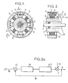
- accelerations measured on rocket 3 which leads to the need for a feedback-type control, and this from a accelerometer A mounted on this rocket.
- This accelerometer provides electrical signals representative of accelerations vertical z and horizontal x, the latter acting on the wheels in the direction of travel of the vehicle.
- the algorithm could then be that of the figure 2a, in which rectangle 6-7 represents the actuator horizontal or vertical concerned, and rectangle 14 a phase correcting circuit. Entrance disruption (horizontal or vertical vibration of the wheel) is shown by arrow 15, and is therefore exerted on rocket 3 concurrently with the output of the actuator 6-7.
- the accelerometer A provided by the feedback loop 16 a control signal, representative of the acceleration residual on the rocket, to an operator 17 receiving on his other input 18 a zero reference signal.
- FIG. 3 makes it possible to modify this diagram using a signal accelerometer reference Ar placed on the housing 11 and an accelerometer AE on rocket 3, whose signal therefore represents the residual accelerations undergone by the wheel, according to directions z and x above.
- FIG. 3a shows the diagram of the algorithm then usable, which is of the type called "feed-forward".
- Hp represents the transfer (or transmittance) function between the reference accelerations noted on the housing 11 (receiving the vibrations of the wheel), and residual accelerations recorded on rocket 3, measured by the AE accelerometer.
- the signal for these accelerations is used to set an F filter arranged in the actuator loop 6, 7, between the accelerometer output Ar and the rocket 3.
- the invention is directly creates the power required for power actuators using an alternator between the rim and the wheel brake caliper, the part attached to the caliper being the stator, and the part fixed to the rim being the rotor.
- the stator is powered so as to create an induction magnetic in the air gap, and the rotor is wound so to be able to recover the current induced during the rotation of wheel.
- stator supply current allows to control the vertical and horizontal forces to be created on the rim through actuators.
- stator is wound with two independent windings which create two magnetic induction distributions in the air gap of the wheel alternator, the first winding allowing create the vertical forces in the z direction, and the second winding to create horizontal forces in the direction x.
- FIG. 6 is shown by way of example a winding 19 of stator 20 for creating the vertical forces (it being understood that the same principle could be used to generate the horizontal forces), this stator 20 being mounted for example on a bracket Disc brake 26, as shown in FIG. 12.
- the arrow I S in FIG. 6 represents the supply current of the stator; in FIG. 12, I SH designates the supply current of the stator winding capable of creating the horizontal forces and I SV designates the supply current of the stator winding capable of creating the vertical forces.
- FIG. 13 a variant is shown according to which control of the different actuators 6'-7 'is determined by a computer 28 mounted directly in the rim and connected to the rotor 21 by a rectifier circuit 29 also mounted in the rim.
- the stator 20 is still mounted on the disc brake caliper 25, and can be powered in constant current.
Landscapes
- Engineering & Computer Science (AREA)
- General Engineering & Computer Science (AREA)
- Mechanical Engineering (AREA)
- Physics & Mathematics (AREA)
- Acoustics & Sound (AREA)
- Aviation & Aerospace Engineering (AREA)
- Electromagnetism (AREA)
- Arrangement Or Mounting Of Propulsion Units For Vehicles (AREA)
- Connection Of Motors, Electrical Generators, Mechanical Devices, And The Like (AREA)
Claims (11)
- Vorrichtung zur Dämpfung von Rollgerauschen oder Rollschwingungen bei Fahrzeugrädern, enthaltend je Rad eine oder mehrere um die Achswelle (2, 2') dieses Rades herum angeordnete träge Massen (5), wobei die Massen (5) mit einem drehbeweglich angeordneten Bauelement (3) verbunden und derart am Rad befestigt sind, daß sie die Schwingungen aufnehmen, dadurch gekennzeichnet, daß die Massen (5) über gesteuerte Betätigungselemente (6 bis 8, 6' bis 8'), bei denen es sich um Motoren mit veränderlichem magnetischen Widerstand handelt, mit dem drehbeweglich angeordneten Bauelement (3') verbunden sind, wobei das Bauelement (3') ein Achsschenkel der Achswelle sein kann oder stattdessen auch ein sich drehendes Bauelement (3', 3"), wie etwa eine Felge (3") des Rades, das auf eine solche Weise einstückig mit dem Rad ausgebildet ist, daß es dessen Schwingungen aufnimmt.
- Vorrichtung nach Anspruch 1, gekennzeichnet durch elastische Elemente (9), die geeignet sind, die zwischen der trägen Masse bzw. den trägen Massen (5, 6; 5', 6') und dem Bauelement (3, 3') auftretenden statischen Kräfte aufzunehmen.
- Vorrichtung nach Anspruch 1 oder 2, gekennzeichnet durch eine zusätzliche schwingungsdämpfende Schicht (12, 13), die zwischen dem Bauelement (3) und einem starren, über Lager (1) auf der Achswelle (2) des Rades befestigten Gehäuse (11) angeordnet ist.
- Vorrichtung nach Anspruch 3, dadurch gekennzeichnet, daß die schwingungsdämpfende Schicht Elastomerblöcke (12) mit geringer radialer Steifigkeit und als axiale Anschlagelemente dienende Elastomerblöcke (13) mit hoher Steifigkeit aufweist.
- Vorrichtung nach einem der vorangegangenen Ansprüche, dadurch gekennzeichnet, daß die träge Masse bzw. die trägen Massen (5) und die Betätigungselemente relativ zum Achsschenkel (3) nach Innen hin angeordnet sind.
- Vorrichtung gemäß Anspruch 1 oder 2, dadurch gekennzeichnet, daß die Betätigungselemente mit veränderbarem magnetischem Widerstand (6' bis 8'), die durch Linearmotoren mit verstellbarem magnetischen Widerstand gebildet werden, ebenso wie ein sie speisender Wechselstromgenerator an der Felge (3") des Rades angebracht sind.
- Vorrichtung nach Anspruch 1 oder 2, dadurch gekennzeichnet, daß der Achsschenkel (3) einstückig mit einem Geschwindigkeitsmeßgerät (A) ausgebildet ist, welches Signale liefern kann, die einer auf das Rad in vertikaler (z) bzw. horizontaler (x) Richtung einwirkenden Beschleunigung entsprechen.
- Vorrichtung nach Anspruch 3 oder 4, gekennzeichnet durch ein mit dem steifen Gehäuse (11) einstückig ausgebildetes Referenzgeschwindigkeitsmeßgerät (Ar), welches Signale liefern kann, die der Beschleunigung des Rades in vertikaler (z) bzw. in horizontaler (x) Richtung entsprechen, sowie durch ein mit dem Achsschenkel (3) einstückig ausgebildetes Geschwindigkeitsmeßgerät (Aε), welches Signale liefert, die der jeweiligen Restbeschleunigung in diesen Richtungen entsprechen, wobei diese unterschiedlichen Signale in einem Algorithmus vom "Mischkopplungs"-Typ eingesetzt werden.
- Vorrichtung nach Anspruch 6, dadurch gekennzeichnet, daß der Wechselstromgenerator einen auf dem Sattel (25) einer Scheibenbremse angeordneten Stator (20) und einen Rotor (21) umfaßt, dessen Induktionswindungen (23, 24) mit den Spulen (7') der Betätigungselemente in Verbindung stehen.
- Vorrichtung nach Anspruch 9, enthaltend zwei Paare von Betätigungselementen (6 bis 7, 6' bis 7'), die sich paarweise diametral gegenüberliegen, dadurch gekennzeichnet daß der Rotor (21) zwei um 90° zueinander versetzte Induktionswindungen (23, 24) aufweist.
- Vorrichtung nach Anspruch 9, dadurch gekennzeichnet, daß der Rotor (21) des Wechselstromgenerators die Betätigungselemente (6' bis 7') über eine Gleichrichterschaltung (29) und einen Rechner (28) speist.
Applications Claiming Priority (2)
| Application Number | Priority Date | Filing Date | Title |
|---|---|---|---|
| FR9305862A FR2705418B1 (fr) | 1993-05-14 | 1993-05-14 | Dispositif d'atténuation des bruits de roulement des véhicules. |
| FR9305862 | 1993-05-14 |
Publications (2)
| Publication Number | Publication Date |
|---|---|
| EP0624737A1 EP0624737A1 (de) | 1994-11-17 |
| EP0624737B1 true EP0624737B1 (de) | 1998-01-21 |
Family
ID=9447161
Family Applications (1)
| Application Number | Title | Priority Date | Filing Date |
|---|---|---|---|
| EP94401063A Expired - Lifetime EP0624737B1 (de) | 1993-05-14 | 1994-05-11 | Vorrichtung zur Verminderung des Laufgeräusches von Fahrzeugen |
Country Status (5)
| Country | Link |
|---|---|
| US (1) | US5468055A (de) |
| EP (1) | EP0624737B1 (de) |
| JP (1) | JPH07305743A (de) |
| DE (1) | DE69408032T2 (de) |
| FR (1) | FR2705418B1 (de) |
Families Citing this family (43)
| Publication number | Priority date | Publication date | Assignee | Title |
|---|---|---|---|---|
| US5906254A (en) * | 1994-10-12 | 1999-05-25 | Lord Corporation | Active systems and devices including active vibration absorbers (AVAS) |
| GB9610253D0 (en) * | 1996-05-16 | 1996-07-24 | Holset Engineering Co | An isolating device |
| AU722808B2 (en) * | 1997-01-31 | 2000-08-10 | Kenneth Sydney Hoskins | Wheel noise reduction |
| DE29818444U1 (de) * | 1998-10-16 | 2000-02-24 | Müller, Gerd, Dipl.-Ing., 66459 Kirkel | Fahrzeugrad |
| FR2801083B1 (fr) * | 1999-11-17 | 2002-01-04 | Renault | Procede et dispositif pour reduire les acyclismes d'un arbre tournant tel qu'un vilebrequin entraine par un moteur de vehicule automobile, et ensemble motopropulseur equipe d'un tel dispositif |
| JP4845323B2 (ja) * | 2000-06-30 | 2011-12-28 | ビステック, インコーポレイテッド | 機械的信号フィルタ |
| AU2002310051A1 (en) * | 2001-05-23 | 2002-12-03 | Bryan P. Prucher | Motor in wheel electric drive system |
| US7387306B2 (en) | 2002-01-29 | 2008-06-17 | Woflcraft Gmbh | Dolly |
| DE10260719B4 (de) * | 2002-01-29 | 2016-11-24 | Wolfcraft Gmbh | Transportkarre |
| CN1684851B (zh) * | 2002-08-29 | 2010-05-05 | 株式会社普利司通 | 轮内马达系统 |
| US6889803B2 (en) * | 2002-10-11 | 2005-05-10 | American Axle & Manufacturing, Inc. | Torsional active vibration control system |
| JP4575298B2 (ja) * | 2003-12-22 | 2010-11-04 | 株式会社ブリヂストン | インホイールモータシステム |
| JP2005206140A (ja) * | 2003-12-24 | 2005-08-04 | Bridgestone Corp | インホイールモータシステム |
| JP4287319B2 (ja) * | 2004-04-05 | 2009-07-01 | 株式会社ブリヂストン | インホイールモータシステム |
| JP4139353B2 (ja) * | 2004-05-25 | 2008-08-27 | トヨタ自動車株式会社 | 車輪支持装置 |
| US20060290200A1 (en) * | 2005-06-24 | 2006-12-28 | Davison Kent E | Wheel-end mounted multipurpose acceleration sensing device |
| US7862056B2 (en) * | 2007-02-02 | 2011-01-04 | Ford Global Technologies, Llc | Steering gear inertia damper |
| CN101550986B (zh) * | 2009-05-02 | 2011-06-22 | 罗清 | 主动控制型电动扭振减振器及其实现方法 |
| DE102009022872A1 (de) * | 2009-05-27 | 2010-12-02 | Voith Turbo Smi Technologies Gmbh & Co. Kg | Kraftfahrzeug mit einem Retarder |
| WO2014044496A2 (en) * | 2012-09-19 | 2014-03-27 | Asml Netherlands B.V. | Method of calibrating a reluctance actuator assembly, reluctance actuator and lithographic apparatus comprising such reluctance actuator |
| CN103267107A (zh) * | 2013-05-10 | 2013-08-28 | 哈尔滨工程大学 | 一种布拉格型压电声子晶体减振齿轮 |
| KR102152577B1 (ko) * | 2014-12-09 | 2020-09-07 | 현대자동차주식회사 | 공명음을 저감시킬 수 있는 휠캡 |
| US10300760B1 (en) | 2015-03-18 | 2019-05-28 | Apple Inc. | Fully-actuated suspension system |
| DE102015009259A1 (de) * | 2015-07-16 | 2016-06-23 | Audi Ag | Radaufhängung |
| DE102017103811A1 (de) * | 2017-02-24 | 2018-08-30 | Inventus Engineering Gmbh | Fahrwerkkomponente mit einem Drehdämpfer |
| US10814690B1 (en) | 2017-04-18 | 2020-10-27 | Apple Inc. | Active suspension system with energy storage device |
| CN110997362B (zh) | 2017-05-08 | 2023-07-28 | 苹果公司 | 主动悬架系统 |
| US10899340B1 (en) | 2017-06-21 | 2021-01-26 | Apple Inc. | Vehicle with automated subsystems |
| US11173766B1 (en) | 2017-09-07 | 2021-11-16 | Apple Inc. | Suspension system with locking structure |
| US11065931B1 (en) | 2017-09-15 | 2021-07-20 | Apple Inc. | Active suspension system |
| US11124035B1 (en) | 2017-09-25 | 2021-09-21 | Apple Inc. | Multi-stage active suspension actuator |
| US10960723B1 (en) * | 2017-09-26 | 2021-03-30 | Apple Inc. | Wheel-mounted suspension actuators |
| US11285773B1 (en) | 2018-09-12 | 2022-03-29 | Apple Inc. | Control system |
| US11634167B1 (en) | 2018-09-14 | 2023-04-25 | Apple Inc. | Transmitting axial and rotational movement to a hub |
| US11345209B1 (en) | 2019-06-03 | 2022-05-31 | Apple Inc. | Suspension systems |
| US11938922B1 (en) | 2019-09-23 | 2024-03-26 | Apple Inc. | Motion control system |
| US11179991B1 (en) | 2019-09-23 | 2021-11-23 | Apple Inc. | Suspension systems |
| US11707961B1 (en) | 2020-04-28 | 2023-07-25 | Apple Inc. | Actuator with reinforcing structure for torsion resistance |
| US11897557B2 (en) | 2020-06-02 | 2024-02-13 | Deere & Company | Track assembly vibration limiting system and method |
| US11828339B1 (en) | 2020-07-07 | 2023-11-28 | Apple Inc. | Vibration control system |
| CN117396339A (zh) | 2021-06-07 | 2024-01-12 | 苹果公司 | 质量阻尼器系统 |
| US12251973B2 (en) | 2022-06-10 | 2025-03-18 | Apple Inc. | Vibration absorber |
| US12168375B1 (en) | 2023-01-26 | 2024-12-17 | Apple Inc. | Motion control system |
Family Cites Families (20)
| Publication number | Priority date | Publication date | Assignee | Title |
|---|---|---|---|---|
| DE325363C (de) * | 1917-05-04 | 1920-12-16 | Siemens Schuckertwerke G M B H | Einrichtung zur Daempfung von Verdrehungsschwingungen umlaufender Wellen |
| US1655807A (en) * | 1926-10-18 | 1928-01-10 | Trinity Wheel Corp | Brake drum and wheel construction |
| US2034816A (en) * | 1933-12-26 | 1936-03-24 | Huguenin Albert | Wheel for vehicles running on rails |
| NL58578C (de) * | 1938-07-19 | 1900-01-01 | ||
| NL276156A (de) * | 1961-04-25 | |||
| SU868182A1 (ru) * | 1978-01-06 | 1981-09-30 | Московский Ордена Трудового Красного Знамени Автомобильно-Дорожный Институт | Магнитный виброизол тор |
| DE2922585B1 (de) * | 1979-06-02 | 1980-12-11 | Krupp Ag Huettenwerke | Schwingungsabsorber fuer Resonanzschwingungen rotierender Koerper |
| JPS59501945A (ja) * | 1982-07-07 | 1984-11-22 | ヴオロシロフグラ−ドスキ− マシノストロイチエルヌイ インスチツ−ト | 鉄道車両用弾性車輪 |
| GB2192041B (en) * | 1986-06-24 | 1990-10-10 | Fokker Bv | Vibration absorber with controllable resonance frequency |
| FR2609133B1 (fr) * | 1986-12-31 | 1989-12-15 | Mecanique Magnetique Sa | Dispositif electromagnetique de reduction des vibrations dans une machine tournante equipee de paliers fluides |
| GB8710998D0 (en) * | 1987-05-08 | 1987-06-10 | Btr Plc | Vehicle engine suspension systems |
| SU1449360A1 (ru) * | 1987-06-24 | 1989-01-07 | Ворошиловградский машиностроительный институт | Ведуща колесна пара рельсового транспортного средства с односторонним расположением ведомой шестерни на оси |
| US4935651A (en) * | 1987-12-04 | 1990-06-19 | Hyundai Heavy Industries Co., Ltd. | Automatically controlled dynamic absorber |
| US4991698A (en) * | 1988-05-16 | 1991-02-12 | Bose Corporation | Damping with damping mass inside wheel |
| DE68903245T2 (de) * | 1988-05-16 | 1993-09-16 | Bose Corp | Fahrzeugaufhaengungssystem. |
| JPH0263901A (ja) * | 1988-07-12 | 1990-03-05 | Nippon Dorai Suraido Kk | 鉄道用消音車輪 |
| DE4004333A1 (de) * | 1989-03-08 | 1990-09-13 | Volkswagen Ag | Schwingungstilger fuer kraftfahrzeug-raeder |
| DE4007443A1 (de) * | 1989-03-16 | 1991-09-12 | Topexpress Ltd | Aktive vibrationssteuerung |
| DE4138405C1 (de) * | 1991-11-22 | 1993-02-25 | Fa. Carl Freudenberg, 6940 Weinheim, De | |
| DE9209913U1 (de) * | 1992-07-23 | 1993-07-22 | Delic, Dusan, 79639 Grenzach-Wyhlen | Schwingungsdämpfer |
-
1993
- 1993-05-14 FR FR9305862A patent/FR2705418B1/fr not_active Expired - Lifetime
-
1994
- 1994-05-11 EP EP94401063A patent/EP0624737B1/de not_active Expired - Lifetime
- 1994-05-11 DE DE69408032T patent/DE69408032T2/de not_active Expired - Fee Related
- 1994-05-13 US US08/242,096 patent/US5468055A/en not_active Expired - Fee Related
- 1994-05-16 JP JP6101315A patent/JPH07305743A/ja active Pending
Also Published As
| Publication number | Publication date |
|---|---|
| DE69408032T2 (de) | 1998-05-20 |
| DE69408032D1 (de) | 1998-02-26 |
| JPH07305743A (ja) | 1995-11-21 |
| FR2705418B1 (fr) | 1995-08-04 |
| US5468055A (en) | 1995-11-21 |
| EP0624737A1 (de) | 1994-11-17 |
| FR2705418A1 (fr) | 1994-11-25 |
Similar Documents
| Publication | Publication Date | Title |
|---|---|---|
| EP0624737B1 (de) | Vorrichtung zur Verminderung des Laufgeräusches von Fahrzeugen | |
| EP1553324B1 (de) | Lagerträger mit doppelter Steifigkeit | |
| EP0275791B1 (de) | Elektromagnetische Einrichtung zur Begrenzung der Schwingungen in einer drehenden Maschine mit Flüssigkeitslagerung | |
| FR2760492A1 (fr) | Systeme de production d'energie electrique associe a une eolienne | |
| CA1204821A (fr) | Agencement de roue cinetique a paliers magnetiques, notamment pour le stockage d'energie | |
| FR2500688A1 (fr) | Groupe electrique d'entrainement avec poulie supportee par le carter | |
| EP0995260B1 (de) | Rotierendes elektromotorisches system mit schwingungsfähigkeit und verfahren zum betrieb eines rotierenden elektromotors mit schwingungsfähigkeit | |
| FR2794204A1 (fr) | Systeme d'amortissement de vibrations pour un systeme d'entrainement d'un vehicule automobile | |
| CA3106491A1 (fr) | Dispositif roulant adapte a rouler sur un sol | |
| EP0509911B1 (de) | Hybridschwingungsdämpfer mit aktivem magnetischen Schwingungserzeuger | |
| FR2728695A1 (fr) | Dispositif de commande en rotation de grande precision, notamment pour telescope | |
| FR2768995A1 (fr) | Resonateur pendulaire de tete de rotor | |
| FR3020427A1 (fr) | Dispositif de transmission de couple, notamment pour vehicule automobile | |
| FR2662099A1 (fr) | Vibreur basse frequence a grande amplitude. | |
| FR2986842A1 (fr) | Dispositif de reduction des vibrations actif peu couteux constitue de plots elastiques | |
| EP0381575A1 (de) | Mechanisches Stabilisierungssystem mit Gegendrehung und einzigem Motor | |
| FR3084126A1 (fr) | Systeme de transmission pour engin electrique roulant comprenant deux boitiers fermes par une meme plaque et un mecanisme de transmission formant pont entre ces derniers | |
| WO2013114043A2 (fr) | Machine électrique présentant une structure statorique modulaire | |
| FR2857072A1 (fr) | Dispositif anti-vibratoire | |
| FR2785734A1 (fr) | Dispositif magnetique pour corps tournant et ensemble mecanique le comportant | |
| EP0299855A1 (de) | Verfahren zur Verminderung der elektromagnetischen Schwingungen in elektrischen Maschinen und Maschinen, die mit Hilfe eines solchen Verfahrens hergestellt sind | |
| EP0828335A1 (de) | Kraftfahrzeuggenerator mit Dreiphasenwicklungen | |
| WO2025062011A1 (fr) | Roue a dispositif de freinage magnetique; atterrisseur d'aeronef et aeronef equipes d'une telle roue | |
| WO2019048778A1 (fr) | Boitier d'accessoires pour turbomachine | |
| EP4316884A1 (de) | Antriebssystem für ein elektro- oder hybrid-fahrzeug |
Legal Events
| Date | Code | Title | Description |
|---|---|---|---|
| PUAI | Public reference made under article 153(3) epc to a published international application that has entered the european phase |
Free format text: ORIGINAL CODE: 0009012 |
|
| AK | Designated contracting states |
Kind code of ref document: A1 Designated state(s): DE GB IT |
|
| 17P | Request for examination filed |
Effective date: 19941124 |
|
| 17Q | First examination report despatched |
Effective date: 19951012 |
|
| GRAG | Despatch of communication of intention to grant |
Free format text: ORIGINAL CODE: EPIDOS AGRA |
|
| GRAG | Despatch of communication of intention to grant |
Free format text: ORIGINAL CODE: EPIDOS AGRA |
|
| GRAH | Despatch of communication of intention to grant a patent |
Free format text: ORIGINAL CODE: EPIDOS IGRA |
|
| GRAH | Despatch of communication of intention to grant a patent |
Free format text: ORIGINAL CODE: EPIDOS IGRA |
|
| GRAA | (expected) grant |
Free format text: ORIGINAL CODE: 0009210 |
|
| AK | Designated contracting states |
Kind code of ref document: B1 Designated state(s): DE GB IT |
|
| GBT | Gb: translation of ep patent filed (gb section 77(6)(a)/1977) |
Effective date: 19980126 |
|
| REF | Corresponds to: |
Ref document number: 69408032 Country of ref document: DE Date of ref document: 19980226 |
|
| ITF | It: translation for a ep patent filed | ||
| PLBE | No opposition filed within time limit |
Free format text: ORIGINAL CODE: 0009261 |
|
| STAA | Information on the status of an ep patent application or granted ep patent |
Free format text: STATUS: NO OPPOSITION FILED WITHIN TIME LIMIT |
|
| 26N | No opposition filed | ||
| REG | Reference to a national code |
Ref country code: GB Ref legal event code: IF02 |
|
| PGFP | Annual fee paid to national office [announced via postgrant information from national office to epo] |
Ref country code: GB Payment date: 20030506 Year of fee payment: 10 |
|
| PGFP | Annual fee paid to national office [announced via postgrant information from national office to epo] |
Ref country code: DE Payment date: 20030512 Year of fee payment: 10 |
|
| PG25 | Lapsed in a contracting state [announced via postgrant information from national office to epo] |
Ref country code: GB Free format text: LAPSE BECAUSE OF NON-PAYMENT OF DUE FEES Effective date: 20040511 |
|
| PG25 | Lapsed in a contracting state [announced via postgrant information from national office to epo] |
Ref country code: DE Free format text: LAPSE BECAUSE OF NON-PAYMENT OF DUE FEES Effective date: 20041201 |
|
| GBPC | Gb: european patent ceased through non-payment of renewal fee |
Effective date: 20040511 |
|
| PG25 | Lapsed in a contracting state [announced via postgrant information from national office to epo] |
Ref country code: IT Free format text: LAPSE BECAUSE OF NON-PAYMENT OF DUE FEES;WARNING: LAPSES OF ITALIAN PATENTS WITH EFFECTIVE DATE BEFORE 2007 MAY HAVE OCCURRED AT ANY TIME BEFORE 2007. THE CORRECT EFFECTIVE DATE MAY BE DIFFERENT FROM THE ONE RECORDED. Effective date: 20050511 |