EP0995260B1 - Rotierendes elektromotorisches system mit schwingungsfähigkeit und verfahren zum betrieb eines rotierenden elektromotors mit schwingungsfähigkeit - Google Patents
Rotierendes elektromotorisches system mit schwingungsfähigkeit und verfahren zum betrieb eines rotierenden elektromotors mit schwingungsfähigkeit Download PDFInfo
- Publication number
- EP0995260B1 EP0995260B1 EP98925347A EP98925347A EP0995260B1 EP 0995260 B1 EP0995260 B1 EP 0995260B1 EP 98925347 A EP98925347 A EP 98925347A EP 98925347 A EP98925347 A EP 98925347A EP 0995260 B1 EP0995260 B1 EP 0995260B1
- Authority
- EP
- European Patent Office
- Prior art keywords
- electric motor
- vibrating
- stator
- control signal
- rotor
- Prior art date
- Legal status (The legal status is an assumption and is not a legal conclusion. Google has not performed a legal analysis and makes no representation as to the accuracy of the status listed.)
- Expired - Lifetime
Links
- 238000000034 method Methods 0.000 title claims abstract description 16
- 238000012360 testing method Methods 0.000 claims description 9
- 230000001360 synchronised effect Effects 0.000 claims description 5
- 230000001939 inductive effect Effects 0.000 abstract 1
- 238000011156 evaluation Methods 0.000 description 5
- 239000004020 conductor Substances 0.000 description 4
- 238000010586 diagram Methods 0.000 description 4
- 230000002093 peripheral effect Effects 0.000 description 4
- 238000006243 chemical reaction Methods 0.000 description 3
- 239000000463 material Substances 0.000 description 3
- 229910000838 Al alloy Inorganic materials 0.000 description 2
- XEEYBQQBJWHFJM-UHFFFAOYSA-N Iron Chemical compound [Fe] XEEYBQQBJWHFJM-UHFFFAOYSA-N 0.000 description 2
- 230000000295 complement effect Effects 0.000 description 2
- 238000005259 measurement Methods 0.000 description 2
- 238000004804 winding Methods 0.000 description 2
- ZOXJGFHDIHLPTG-UHFFFAOYSA-N Boron Chemical compound [B] ZOXJGFHDIHLPTG-UHFFFAOYSA-N 0.000 description 1
- 229910052779 Neodymium Inorganic materials 0.000 description 1
- 229910000831 Steel Inorganic materials 0.000 description 1
- 229910052796 boron Inorganic materials 0.000 description 1
- 239000003990 capacitor Substances 0.000 description 1
- 230000006835 compression Effects 0.000 description 1
- 238000007906 compression Methods 0.000 description 1
- 239000000428 dust Substances 0.000 description 1
- 229920001971 elastomer Polymers 0.000 description 1
- 239000000806 elastomer Substances 0.000 description 1
- 238000007689 inspection Methods 0.000 description 1
- 229910052742 iron Inorganic materials 0.000 description 1
- 229910052751 metal Inorganic materials 0.000 description 1
- 239000002184 metal Substances 0.000 description 1
- QEFYFXOXNSNQGX-UHFFFAOYSA-N neodymium atom Chemical compound [Nd] QEFYFXOXNSNQGX-UHFFFAOYSA-N 0.000 description 1
- 238000009659 non-destructive testing Methods 0.000 description 1
- 230000035515 penetration Effects 0.000 description 1
- 230000005236 sound signal Effects 0.000 description 1
- 239000010959 steel Substances 0.000 description 1
- 238000010408 sweeping Methods 0.000 description 1
- 210000002105 tongue Anatomy 0.000 description 1
- XLYOFNOQVPJJNP-UHFFFAOYSA-N water Substances O XLYOFNOQVPJJNP-UHFFFAOYSA-N 0.000 description 1
Images


Classifications
-
- H—ELECTRICITY
- H02—GENERATION; CONVERSION OR DISTRIBUTION OF ELECTRIC POWER
- H02P—CONTROL OR REGULATION OF ELECTRIC MOTORS, ELECTRIC GENERATORS OR DYNAMO-ELECTRIC CONVERTERS; CONTROLLING TRANSFORMERS, REACTORS OR CHOKE COILS
- H02P27/00—Arrangements or methods for the control of AC motors characterised by the kind of supply voltage
-
- G—PHYSICS
- G01—MEASURING; TESTING
- G01M—TESTING STATIC OR DYNAMIC BALANCE OF MACHINES OR STRUCTURES; TESTING OF STRUCTURES OR APPARATUS, NOT OTHERWISE PROVIDED FOR
- G01M7/00—Vibration-testing of structures; Shock-testing of structures
- G01M7/02—Vibration-testing by means of a shake table
- G01M7/022—Vibration control arrangements, e.g. for generating random vibrations
-
- H—ELECTRICITY
- H02—GENERATION; CONVERSION OR DISTRIBUTION OF ELECTRIC POWER
- H02P—CONTROL OR REGULATION OF ELECTRIC MOTORS, ELECTRIC GENERATORS OR DYNAMO-ELECTRIC CONVERTERS; CONTROLLING TRANSFORMERS, REACTORS OR CHOKE COILS
- H02P25/00—Arrangements or methods for the control of AC motors characterised by the kind of AC motor or by structural details
- H02P25/02—Arrangements or methods for the control of AC motors characterised by the kind of AC motor or by structural details characterised by the kind of motor
- H02P25/032—Reciprocating, oscillating or vibrating motors
-
- G—PHYSICS
- G01—MEASURING; TESTING
- G01H—MEASUREMENT OF MECHANICAL VIBRATIONS OR ULTRASONIC, SONIC OR INFRASONIC WAVES
- G01H3/00—Measuring characteristics of vibrations by using a detector in a fluid
Definitions
- the present invention relates to a motorized system rotational electric vibrator and a method to make operate a rotating electric motor capable of vibrating having a rotor and a stator.
- the rotor and the stator forming a unit capable of vibrating allowing mechanical vibrations.
- the unit includes a radiator rotary acoustic device comprising an enclosure having a wall cylindrical side and end walls forming together a cylindrical chamber.
- An engine is planned to rotate a rotor in a rotary motion and alternative.
- the apparatus described in this patent is capable of reproduce sounds with very little distortion from from a frequency of 80 Hertz to a lower frequency around 20 Hertz in the audible frequency range.
- Japanese Patent 63-138230 discloses a device for analyzing car vibrations.
- the objective of this invention is to carry out an evaluation of the components of an automobile by subjecting it to vibrations. To make such a evaluation, the front and rear wheels of the automobile are placed on rollers and the automobile is started. A vibration signal is detected and analyzed to allow the evaluation of the components of the automobile.
- An object of the present invention is to propose a rotary electric motorized system capable of vibrating and a method for operating an electric motor rotary vibrating device where the electric motor can vibrate according to a range of audible frequencies regardless of whether or not he is in rotation.
- a rotating electric motorized system able to vibrate according to the present invention. It includes an engine electrical 7 having a rotor and a stator. Engine electric will be described in more detail when we refer to Figures 5 and 6.
- the electric motor is preferably a synchronous electric wheel motor with permanent magnets.
- the rotor and the stator form a unit capable of vibrating having a first bandwidth allowing mechanical vibrations inside a audible frequency range.
- An amplifier of power 4 is provided to power the electric motor 7.
- This power amplifier has an output of power 6 connected to the electric motor 7 and an input of a control signal 8 to receive a signal from control.
- the power amplifier 4 has a second bandwidth including at least the first band bandwidth.
- a signal generator 11 is provided to generate the control signal.
- the signal generator 11 has a third bandwidth including at least the first bandwidth.
- the control signal has a component continues to rotate the rotor relative to stator, and an alternative component to induce mechanical vibrations in the unit able to vibrate at within a range of audible frequencies.
- the signal generator 11 includes a signal generator audio 30 to generate an alternative component that will do vibrate the unit composed of the rotor and the stator of the motor 7.
- a control signal generator 32 is also planned to generate a continuous component that will induce a rotation of the rotor relative to the stator.
- a adder 34 is provided for adding the signal of output of the audio signal generator 30 to the signal of output of the control signal generator 32 and produce a control signal that will be applied to the input of control 8 of the power amplifier 4.
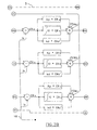
- the power amplifier 4 comprises a regulator of current 3 and a converter 5.
- the motor-wheel electrical 7 is preferably a synchronous machine three-phase permanent magnets.
- the output signal of the signal generator 11 is sent to the current regulator 3.
- the regulator current 3 also receives via its input 16 a signal encoded the position of the rotor of the machine 7 of the encoder 9, via its inputs 18 three current measurements of the output 6, and via its input 35 the signal of the power supply Vdc. Each current measurement represents a current flowing in one of the three phases of the synchronous machine 7. Based on the signals received by the current regulator 3 via inputs 8, 16, 18 and 35, this produces modulation signals by pulses of variable width PWMa, PWMb and PWMc at its output 20 that are sent to the input 21 of the converter 5.
- Control current values Iac, Ibc and Icc are calculated from the values AVE and PVE derived from inputs 16 and 8.
- the values of force against Electromotive FEMa, FEMb and FEMc are calculated from values PVE, ⁇ and ⁇ d where ⁇ d is a constant representative of the magnetomotive force.
- the values of errors ERa, ERb and ERc are calculated from current control values Iac, Ibc and Icc and values of currents Ia, Ib and Ic.
- the values REa, REb and REc are calculated using a PID algorithm (Proportional Integral Differential) which uses the values of FEMa, FEMb and FEMc.
- the values PWMa, PWMb and PWMc are calculated from the values of Vdc, REa, REb and REc and are applied to the output 20.
- FIG. 1 we show a preferred embodiment of the converter 5 shown in Figure 1.
- This converter 5 is used to apply power currents to the electric motor 7 shown in Figure 1 via the outputs 6.
- Six switches IGBT type power supplies 22 are connected to the power supply Vdc via the input 24.
- the power switches 22 have 26 inputs for receive control signals from the outputs of control circuit 28.
- the control circuits 28 have inputs 30 to respectively receive the signals PWMa, PWMb and PWMc via input 21.
- a capacitor of power 32 is connected in parallel to the input 24 for filter the power supply Vdc, and is used as decoupling of the converter 5.
- the converter 5 receives signals PWMa, PWMb and PWMc and amplifies them.
- Three power signals are sent to the machine 7 via the outputs 6 to induce a rotation and a vibration of the machine 7 according to the signals emitted respectively by the generators 32 and 30.
- the method to operate the engine rotary electric device capable of vibrating 7 includes the steps of (a) produce a control signal having a component continues to rotate the rotor relative to stator, and an alternative component to induce mechanical vibrations within a range of audible frequencies in the unit composed of the rotor and the stator of the electric motor; (b) produce a signal in response to the control signal produced at step (a) for powering the electric motor 7; and (c) power the electric motor 7 with the signal Power. So, in operation, the electric motor vibrates in response to the alternative component of the signal of control and the rotor rotates in response to the component continuous control signal.
- FIG 4 we show a second embodiment of the invention which an apparatus and method for locating a noise due to an unwanted vibration problem in a electric wheel motor 7 or in a vehicle equipped with less an electric wheel motor 7.
- the same numerical benchmarks as those appearing in the Figure 1 indicate similar elements.
- the mechanic must perform vibration tests on different parts of the engine electric or vehicle.
- An object of this second mode of realization is to propose a system and method for locate easily and accurately a noise due to a unwanted vibration.
- the signal generator 11 includes a scan generator 23 for generating a control signal having an alternative component of sweeping to perform a mechanical vibration test on the electric motor 7 or the armature 40 connected to the electric motor 7.
- a link mechanical is of course planned to connect the engine electrical 7 to the frame 40 so that the test of Mechanical vibration can be performed on the frame.
- electric wheel motors are represented by the electric motors 7 and where the part remaining of the automobile constitutes the frame 40.
- the scanning of frequency signals is carried out at within a range of audible frequencies with predetermined amplitudes for performing the test of mechanical vibrations on the vehicle.
- the generator scan 23 generates a scan of frequency signals that are combined with the control signals generated by the control signal generator 32 via the adder 34.
- the output signal of the adder 34 supplies the current regulator 3 which produces in turn pulse modulated signals variable width PWMa, PWMb and PWMc also commonly called PWM signals which are then sent to the converter 5 which converts the PWM signals into three-phase signals supplying the electric motor 7.
- a microphone 29 is provided to pick up noises due to mechanical vibrations generated by the vehicle. The noises measured will help locate the vehicle parts causing said noises.
- the system further includes a dB 27 meter connected to the microphone 29 for indicate the level of noise present near the vehicle 15.
- the method according to this second embodiment includes the following steps of (a) producing a scan of frequency signals in a frequency range audible with predetermined amplitudes; (b) apply the signals produced in step (a) at the input of a amplifier 4 controlling the electric motor-wheel 7 attached to the vehicle 15; and (c) pick up noises due to vibrations generated by the vehicle by means of a microphone 29 during the scanning of the frequency signals to locate the parts in the vehicle producing unwanted vibrations.
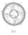
- FIG. 5 and 6 shows a side view partially in section of an embodiment of an electric wheel motor in combination with a rim 28, a tire 32 and a connecting rod articulated 50; and a front view partially in section of the rotor 10 and stator 6 of the electric motor-wheel shown in Figure 5.
- This motor-wheel is known in the art and is described in more detail in US Patent No. 5,327,0344 to P. Couture et al.
- the motor-wheel describes in this patent represents, by way of example only, a engine which can constitute a unit able to vibrate according to the present invention because it has a bandwidth sufficient to allow mechanical vibrations to within a range of audible frequencies.
- other electric motors can be used if they allow mechanical vibrations within a range of audible frequencies.
- the electric wheel motor comprises a hollow shaft 2 having a first opening at one of its ends and a second opening.
- the first opening receives 4 conductors from the outside of the motor-wheel.
- the stator 6 is coaxial with and attached to shaft 2, the stator 6 being provided with hollow portions 11 and coils 8. In Figure 6, only a few winding sections are indicated by No. 8, but it should be understood that there is windings all around the stator 6.
- the rotor 10 is coaxial with the stator 6 and is mounted to be able to turn around the stator 6.
- the stator 6 includes openings forming the hollow portions 11 between the arms 13 to reduce its weight.
- the motor-wheel is also equipped with a conversion system to convert an electric input current into an electric current alternative and variable.
- the conversion system 12 includes a microprocessor unit 44, a converter direct current / alternating current having electronics 14, mounted inside the hollow parts 11, input terminals 15 for receiving the current electrical input brought by means of conductors 4 and output terminals 16 to generate the electric current alternative and variable.
- the frequency of the electric current alternative and variable is representative of a speed of desired rotation of the rotor 10
- the phase angle of the current alternating and variable electric determines if the motor-wheel will work as a motor or as a generator and the amplitude of the alternating and variable current is representative of the desired couple.
- the stator 6 includes a central portion attached to the shaft 2, arms 13 extending radically from the central part, and a circular pole piece and peripheral including metal blades 27 on which coils 8 are wound.
- the pole piece is fixed at the peripheral ends of the arms 13.
- the rotor 10 comprises a housing having a wall cylindrical 17 having an inner surface provided with a means magnetic 26 surrounding the stator and separated from it by a gap. Since the gap is relatively small, it can not be seen in the figures 5 and 6.
- the housing comprises an inner wall 18 disposed on one side of the cylindrical wall 17, and another wall 20 disposed on the other side of the cylindrical wall 17.
- the tree 2 extends through a central part of the inner wall 18. The second opening of said shaft 2 is open inside said housing.
- the housing which is part of the rotor 10 encloses sealed way the shaft 2, the stator 6 and the system of conversion 12.
- a seal 123 is provided.
- the motor-wheel includes a first ball bearing 22 connected to the inner wall 18, and a second ball bearing 24 connected to the outer wall 20.
- the ball bearings 22 and 24 are respectively mounted on both sides of the tree 2 so that the rotor 10 can rotate relative to to the stator 6 by means of ball bearings 22 and 24.
- threaded bolt 23 is provided for fixing the stator 6 by relation to the shaft 2.
- a stop ring 21 is also planned.
- a compression ring 127 is provided to fix the ball bearing 22.
- the stator 6 comprises four arms 13 equally spaced.
- the means magnetic rotor 10 includes a series of magnets 26.
- the stator 6 is made in part of a material of light weight that can lead to heat. Preferably, this material is an aluminum alloy.
- the motor-wheel further comprises a rim 28 fixed around a surface external housing, and a strip 30 made of an elastomer and mounted between the rim 28 and the housing.
- the rim 28 is adapted to receive the tire 32.
- the rim 28 is flat bottom.
- the magnets 26 are preferably made of neodymium, iron and boron.
- the band 30 prevents a water or dust penetration between the housing and the rim 28 to avoid the imbalance of the wheel.
- the peripheral ends of the arms 13 are fixed on the pole piece of the stator 6 by means of a member circular 34 which is an integral part of the extremities peripherals of the arms 13.
- the circular member 34 has his outer surface with notches 36.
- the pole piece of the stator 6 has an internal surface with protruding tongues 37 of complementary shape which are able to cooperate with the notches 36 to fix the pole piece of the stator 6 on the circular member 34.
- the circular member 34 has a internal surface provided with protruding parts 38, thus a efficient exchange of heat can be achieved by means of protruding parts 38 when an air flow is produced inside the housing. Only a few protruding parts are indicated by the number 38 of to avoid overloading Figure 6. Support for stator 6 and the circular member 34 are made of a aluminum alloy while the pole piece of the stator 6 is made of steel.
- protruding parts 38 which are arranged along the limb circular 34 are, in relation to their size longitudinal, preferably out of phase with respect to the motor-wheel shaft, along the direction circumference of limb 34 so as to strengthen it mechanically.
- the central axis 3 is that of the shaft 2.
- the annular section 58 has notches and parts protruding complementary shape which are adapted for cooperate with protruding parts and notches corresponding to the outer border of the annular limb 52. Also, a key 66 is provided to lock the shaft 2 relative to the articulated rod 50.
- the connecting rod articulated 50 is provided with an elongate internal slot 70 having a first end adjacent to the section annular 58 and a second end remote from said annular section 58, so drivers can be brought to the shaft 2 along said elongated slot 70. can also see the ball joint 100.
- the outer wall of the housing includes sections convex and concave 112 and 114 which alternate along its circumferential direction, so that, when the rotor rotates, an air flow is produced inside the housing by means of the section convex 112, and a flow of air is produced along external parts of the concave section 114.
- An air hose 120 is provided. He has one end arranged inside the housing. A room is disposed at the outer end of the pipe 120 and a material desiccation is arranged inside the chamber. Thus when the rotor 10 is rotating, an air circulation is produced inside the pipe 120 and through the room to dry the air inside the housing.
- the tire 32 is attached to the rim 28 in a manner permanent when assembling the motor-wheel.
- the motor-wheel is provided with a flat-bottomed rim 28, a first side flange that can be welded to the rim 28, and a second side flange, which is attached to the rim 28 by means of bolts 146 and an L-shaped member 148 welded on the rim 28.
Landscapes
- Engineering & Computer Science (AREA)
- Power Engineering (AREA)
- Physics & Mathematics (AREA)
- General Physics & Mathematics (AREA)
- Electric Propulsion And Braking For Vehicles (AREA)
- Apparatuses For Generation Of Mechanical Vibrations (AREA)
- Control Of Ac Motors In General (AREA)
- Measurement Of Mechanical Vibrations Or Ultrasonic Waves (AREA)
- Connection Of Motors, Electrical Generators, Mechanical Devices, And The Like (AREA)
- Percussion Or Vibration Massage (AREA)
Claims (6)
- Rotierendes elektrisches Motoranthebssystem, das schwingen kann und umfasst:wobei das elektrische Motorantriebssystem dadurch gekennzeichnet ist, dass die schwingfähige Einheit ein erstes Durchlassband besitzt, das in einem Bereich hörbarer Frequenzen mechanische Schwingungen ermöglicht, der Leistungsverstärker (4) und der Signalgenerator (11) Durchlassbänder besitzen, die das erste Durchlassband enthalten, der Elektromotor (7) ein synchroner elektrischer Radmotor mit Permanentmagneten für ein Fahrzeug ist und der Leistungsverstärker (4) einen Stromregler (3) und einen Umsetzer umfasst.einen Elektromotor (7), der einen Rotor und einen Stator besitzt, wobei der Rotor und der Stator eine schwingfähige Einheit bilden;einen Leistungsverstärker (4), der den Elektromotor (7) speist und einen mit dem Elektromotor (7) verbundenen Leistungsausgang (6) sowie einen Steuersignaleingang (8), der ein Steuersignal empfängt, besitzt; undeinen Signalgenerator (11), der das Steuersignal erzeugt, das eine Gleichstromkomponente zum Drehen des Rotors relativ zum Stator sowie eine Wechselstromkomponente zum Versetzen des Elektromotors (7) in Schwingungen besitzt;
- System nach Anspruch 1, bei dem der Signalgenerator einen Wobbelgenerator (23) umfasst, um ein Steuersignal zu erzeugen, einschließlich eines Wobbelns der Signale mit einer Frequenz im Bereich hörbarer Frequenzen mit vorgegebenen Amplituden, um an dem Fahrzeug eine Prüfung mit mechanischen Schwingungen zu erzeugen.
- System nach Anspruch 2, das außerdem ein Mikrophon (29) umfasst, um ein Geräusch aufzunehmen, das vom Fahrzeug erzeugt wird, um somit jene Teile des Fahrzeugs, die das Geräusch erzeugen, lokalisieren zu können.
- Verfahren zum Betreiben eines Elektromotors (7), der einen Rotor und einen Stator besitzt, wobei der Rotor und der Stator eine schwingfähige Einheit bilden und wobei das Verfahren die folgenden Schritte umfasst:wobei das Verfahren dadurch gekennzeichnet ist, dass die schwingfähige Einheit ein erstes Durchlassband besitzt, das mechanische Schwingungen in einem Bereich hörbarer Frequenzen ermöglicht, der Leistungsverstärker (4) des Schrittes a) und der Signalgenerator (11) des Schrittes b) jeweils Durchlassbänder besitzen, die das erste Durchlassband enthalten, der Elektromotor (7) ein synchroner elektrischer Radmotor mit Permanentmagneten ist und der Leistungsverstärker (4) des Schrittes a) einen Stromregler (3) und einen Umsetzer (5) umfasst.(a) Speisen des Elektromotors (7) mit einem Leistungsverstärker (4), der einen mit dem Elektromotor (7) verbundenen Leistungsausgang (6) und einen Steuersignaleingang (8) zum Empfangen eines Steuersignals besitzt; und(b) Erzeugen des Steuersignals mittels eines Signalgenerators (11), wobei das Steuersignal eine Gleichstromkomponente zum Drehen des Rotors relativ zum Stator und eine Wechselstromkomponente zum Versetzen des Elektromotors (7) in Schwingungen besitzt;
- Verfahren nach Anspruch 4, bei dem das im Schritt (b) erzeugte Steuersignal ein Wobbeln von Signalen mit einer Frequenz im Bereich hörbarer Frequenzen und mit vorgegebenen Amplituden umfasst, um an dem Fahrzeug eine Prüfung mit mechanischen Schwingungen auszuführen.
- Verfahren nach Anspruch 5, das außerdem den Schritt umfasst, bei dem ein vom Fahrzeug erzeugtes Geräusch aufgenommen wird, um jene Teile des Fahrzeugs, die das Geräusch verursachen, zu lokalisieren.
Applications Claiming Priority (3)
| Application Number | Priority Date | Filing Date | Title |
|---|---|---|---|
| CA002208499A CA2208499A1 (en) | 1997-06-16 | 1997-06-16 | Electrically audible motorized wheel assembly and method thereof |
| CA2208499 | 1997-06-16 | ||
| PCT/CA1998/000483 WO1998058446A1 (fr) | 1997-06-16 | 1998-06-10 | Systeme motorise electrique rotatif apte a vibrer et une methode pour faire fonctionner un moteur electrique rotatif apte a vibrer |
Publications (2)
| Publication Number | Publication Date |
|---|---|
| EP0995260A1 EP0995260A1 (de) | 2000-04-26 |
| EP0995260B1 true EP0995260B1 (de) | 2004-12-22 |
Family
ID=4160927
Family Applications (1)
| Application Number | Title | Priority Date | Filing Date |
|---|---|---|---|
| EP98925347A Expired - Lifetime EP0995260B1 (de) | 1997-06-16 | 1998-06-10 | Rotierendes elektromotorisches system mit schwingungsfähigkeit und verfahren zum betrieb eines rotierenden elektromotors mit schwingungsfähigkeit |
Country Status (9)
| Country | Link |
|---|---|
| US (2) | US6229234B1 (de) |
| EP (1) | EP0995260B1 (de) |
| JP (1) | JP2002504853A (de) |
| KR (1) | KR20010013870A (de) |
| AT (1) | ATE285630T1 (de) |
| AU (1) | AU7753198A (de) |
| CA (1) | CA2208499A1 (de) |
| DE (1) | DE69828282T2 (de) |
| WO (1) | WO1998058446A1 (de) |
Cited By (1)
| Publication number | Priority date | Publication date | Assignee | Title |
|---|---|---|---|---|
| CN101281086B (zh) * | 2008-05-20 | 2010-06-09 | 上海电气电站设备有限公司 | 一种大型汽轮发电机定子铁心振动性能分析方法 |
Families Citing this family (18)
| Publication number | Priority date | Publication date | Assignee | Title |
|---|---|---|---|---|
| JP2002514502A (ja) * | 1998-05-08 | 2002-05-21 | ゲディプ・インジェニールビューロ・ウント・イノバツィオーンスベラトゥング・ゲーエムベーハー | 不平衡指向性振動子のための調整装置を動作させるための方法 |
| US6429610B1 (en) * | 2000-09-05 | 2002-08-06 | General Electric Co. | Method and system for reducing motor vibration by controlling flux producing current |
| AU2002310051A1 (en) * | 2001-05-23 | 2002-12-03 | Bryan P. Prucher | Motor in wheel electric drive system |
| US7592900B2 (en) * | 2001-12-05 | 2009-09-22 | Deka Products Limited Partnership | Transporter motor alarm |
| US7268503B2 (en) * | 2002-04-04 | 2007-09-11 | Matsushita Electric Industrial Co., Ltd. | Vibration linear actuating device, method of driving the same device, and portable information apparatus using the same device |
| US20100033315A1 (en) * | 2002-12-03 | 2010-02-11 | Deka Products Limited Partnership | Transporter motor alarm |
| US7213461B2 (en) * | 2004-03-05 | 2007-05-08 | Siemens Power Generation, Inc. | Torsional shaker apparatus for inspecting rotatable power generation machinery |
| DE502007007086D1 (de) * | 2007-12-19 | 2011-06-09 | Klingelnberg Ag | Fertigungsanlage oder Automatisierungsanlage mit Signalerzeugung mittels Direktantrieb und Verfahren zum Erzeugung von Signalen in einer solchen Anlage |
| DE102009042555B4 (de) * | 2009-09-22 | 2021-06-17 | Siemens Mobility GmbH | Prüfverfahren für ein Schienenfahrzeug und Schienenfahrzeug |
| EP2363851B1 (de) * | 2010-03-02 | 2013-07-17 | Siemens Aktiengesellschaft | Vibrations- und Geräuschsteuerungsstrategie in elektrischen Maschinen |
| EP3112826A1 (de) * | 2015-07-02 | 2017-01-04 | Siemens Aktiengesellschaft | Verfahren und umrichter zur lokalisierung einer an einem umrichter angeschlossenen elektrischen maschine oder zur identifizierung eines an der elektrischen maschine angeschlossenen umrichters |
| DE102016201197A1 (de) * | 2016-01-27 | 2017-07-27 | Bayerische Motoren Werke Aktiengesellschaft | Anordnung, Fortbewegungsmittel und Verfahren zur Untersuchung einer mechanischen Struktur |
| RU2672855C1 (ru) * | 2018-02-19 | 2018-11-20 | Федеральное государственное бюджетное образовательное учреждение высшего образования "Петербургский государственный университет путей сообщения Императора Александра I" | Электропривод колебательного движения |
| CN108919114A (zh) * | 2018-04-26 | 2018-11-30 | 江苏大学 | 一种轮毂电机实验台架装置及其实验系统 |
| CN110954826B (zh) * | 2019-12-17 | 2022-01-07 | 四川安和精密电子电器股份有限公司 | 基于音频分析的步进丝杆马达缺陷诊断装置及缺陷识别方法 |
| CN111207896B (zh) * | 2020-01-21 | 2021-05-04 | 苏州市瑞昌机电工程有限公司 | 一种电机性能自动检测装置 |
| US12590862B2 (en) * | 2023-07-07 | 2026-03-31 | Toyota Motor North America, Inc. | Devices, systems, and methods for inducing automotive body vibration |
| CN119508405A (zh) * | 2024-11-18 | 2025-02-25 | 西北工业大学 | 一种高温超导钉扎悬浮主被动混合隔振系统及方法 |
Family Cites Families (40)
| Publication number | Priority date | Publication date | Assignee | Title |
|---|---|---|---|---|
| SU368540A1 (ru) | 1970-12-25 | 1973-01-26 | Библиотека | | |
| US3677077A (en) | 1971-01-07 | 1972-07-18 | George B Merryman | Vibration monitoring system |
| US3844175A (en) | 1973-02-26 | 1974-10-29 | E Hixson | Noise source level detection |
| US3913084A (en) | 1973-03-26 | 1975-10-14 | Wisconsin Alumni Res Found | Noise quality detector for electric motors or other machines |
| JPS566181A (en) | 1979-06-27 | 1981-01-22 | Sanyo Electric Co Ltd | Body detector |
| JPS5617754A (en) | 1979-07-20 | 1981-02-19 | Hitachi Ltd | Vehicle vibration controller |
| JPS5672316A (en) | 1979-11-16 | 1981-06-16 | Hitachi Ltd | Rubbing position identifier |
| US4327518A (en) | 1980-02-27 | 1982-05-04 | Knauff Robert J | Inertial device for sight and sound effects in rotating apparatus |
| JPS57538A (en) | 1980-06-03 | 1982-01-05 | Mitsubishi Heavy Ind Ltd | Inspecting and diagnosing device for automobile or the like |
| ATE38607T1 (de) | 1983-01-28 | 1988-11-15 | Intersonics Inc | Lautsprechersystem fuer sehr tiefe frequenzen. |
| US4522347A (en) | 1983-10-05 | 1985-06-11 | Brunswick Corporation | Drag adjustment click spring assembly |
| US4748659A (en) * | 1984-05-30 | 1988-05-31 | Fujitsu Limited | Calling signal transmission apparatus |
| JPS6388410A (ja) | 1986-10-01 | 1988-04-19 | Babcock Hitachi Kk | 原子炉流体路で発生したル−スパ−ツの監視装置 |
| GB8626059D0 (en) | 1986-10-31 | 1986-12-03 | Helitune Ltd | Testing vehicle |
| JPH068766B2 (ja) | 1986-11-29 | 1994-02-02 | アンリツ株式会社 | 自動車の振動解析装置 |
| JPS63186122A (ja) | 1987-01-28 | 1988-08-01 | Power Reactor & Nuclear Fuel Dev Corp | 構造物の異常診断方式 |
| DE3744802A1 (de) | 1987-04-08 | 1989-07-20 | Helmut Pelzer | Daempfungsmittel zum daempfen der schallabstrahlung als luftschall oder koerperschall fuer ein in der scheibe senkrecht zur achse geteiltes und aus zwei solchen teilen zusammengesetztes rad |
| DE3875398T2 (de) | 1987-06-03 | 1993-04-08 | Kawasaki Steel Co | Vorrichtung zum feststellen von fehlern in lagern. |
| US4793186A (en) | 1987-10-21 | 1988-12-27 | Westinghouse Electric Corp. | Monitoring of exciter shaft torsional vibrations |
| JPH01180425A (ja) | 1988-01-13 | 1989-07-18 | Honda Motor Co Ltd | エンジン振動検出器取り付け装置 |
| JPH0279800A (ja) | 1988-09-14 | 1990-03-20 | Matsushita Electric Works Ltd | ステップモータの制御回路 |
| US4913084A (en) | 1989-04-19 | 1990-04-03 | Seymour Ronald P | Apparatus useful in devices for controlling the thickness of coating applied to a substrate |
| JPH02298825A (ja) | 1989-05-13 | 1990-12-11 | Nippondenso Co Ltd | 回転機のための異常検査装置 |
| JPH0368834A (ja) | 1989-08-08 | 1991-03-25 | Nec Corp | ネジゆるみの検査方法及び装置 |
| US4997404A (en) | 1989-12-06 | 1991-03-05 | May Richard L | Toy vehicle sound system |
| JP2748626B2 (ja) | 1989-12-29 | 1998-05-13 | 日産自動車株式会社 | 能動型騒音制御装置 |
| CH679847A5 (de) | 1990-01-12 | 1992-04-30 | Bruno Mueller | |
| US5029477A (en) | 1990-01-31 | 1991-07-09 | Servo Corporation Of America | Integrity test for acoustic bearing defect detector |
| JPH03289561A (ja) | 1990-04-06 | 1991-12-19 | Iwatsu Electric Co Ltd | 欠陥及び異硬度部分の検出方法及び装置 |
| US5062296A (en) | 1990-09-20 | 1991-11-05 | The United States Of America As Represented By The Department Of Energy | Resonant ultrasound spectroscopy |
| US5191618A (en) | 1990-12-20 | 1993-03-02 | Hisey Bradner L | Rotary low-frequency sound reproducing apparatus and method |
| DE4104961A1 (de) | 1991-02-18 | 1992-08-20 | Siemens Ag | Verfahren und vorrichtung zur pruefung von motoren auf lagerschaeden und/oder unzulaessige vibrationen |
| US5109715A (en) | 1991-02-19 | 1992-05-05 | Fmc Corporation | Location designator for wheel service machines |
| JP2559509Y2 (ja) * | 1991-12-20 | 1998-01-19 | 松下電器産業株式会社 | 速度制御可能なブラシレスモータのコイル焼損防止装置 |
| US5297757A (en) | 1992-07-08 | 1994-03-29 | Abu Garcia Produktion Ab | Buzzer mechanism in a fishing reel |
| JP3448937B2 (ja) | 1994-01-25 | 2003-09-22 | 神鋼電機株式会社 | 振動制御装置 |
| GB2287536A (en) | 1994-03-09 | 1995-09-20 | Ford Motor Co | Identification of vibration induced noises in vehicles |
| JP2997632B2 (ja) * | 1995-04-27 | 2000-01-11 | 核燃料サイクル開発機構 | 回転体に対する電磁的回転加振装置及びそれを用いた回転体の制振装置 |
| DE19531402C2 (de) | 1995-08-26 | 1999-04-01 | Mannesmann Sachs Ag | Vorrichtung und Verfahren zum Beeinflussen von Schwingungen in einem Fahrgastraum eines Kraftfahrzeugs und Vorrichtung und Verfahren zum Erkennen von Defekten an einem Kraftfahrzeug |
| GB2305488B (en) * | 1995-09-21 | 1999-04-28 | Moog Inc | Modular vibratory force generator, and method of operating same |
-
1997
- 1997-06-16 CA CA002208499A patent/CA2208499A1/en not_active Abandoned
-
1998
- 1998-06-10 AU AU77531/98A patent/AU7753198A/en not_active Abandoned
- 1998-06-10 AT AT98925347T patent/ATE285630T1/de not_active IP Right Cessation
- 1998-06-10 US US09/445,805 patent/US6229234B1/en not_active Expired - Fee Related
- 1998-06-10 WO PCT/CA1998/000483 patent/WO1998058446A1/fr not_active Ceased
- 1998-06-10 EP EP98925347A patent/EP0995260B1/de not_active Expired - Lifetime
- 1998-06-10 JP JP50344099A patent/JP2002504853A/ja active Pending
- 1998-06-10 DE DE69828282T patent/DE69828282T2/de not_active Expired - Fee Related
- 1998-06-10 KR KR1019997011892A patent/KR20010013870A/ko not_active Withdrawn
-
2001
- 2001-04-05 US US09/825,984 patent/US6384549B2/en not_active Expired - Fee Related
Cited By (1)
| Publication number | Priority date | Publication date | Assignee | Title |
|---|---|---|---|---|
| CN101281086B (zh) * | 2008-05-20 | 2010-06-09 | 上海电气电站设备有限公司 | 一种大型汽轮发电机定子铁心振动性能分析方法 |
Also Published As
| Publication number | Publication date |
|---|---|
| ATE285630T1 (de) | 2005-01-15 |
| WO1998058446A1 (fr) | 1998-12-23 |
| US6384549B2 (en) | 2002-05-07 |
| US20010017527A1 (en) | 2001-08-30 |
| JP2002504853A (ja) | 2002-02-12 |
| EP0995260A1 (de) | 2000-04-26 |
| DE69828282T2 (de) | 2005-12-08 |
| US6229234B1 (en) | 2001-05-08 |
| AU7753198A (en) | 1999-01-04 |
| CA2208499A1 (en) | 1998-12-16 |
| DE69828282D1 (de) | 2005-01-27 |
| KR20010013870A (ko) | 2001-02-26 |
Similar Documents
| Publication | Publication Date | Title |
|---|---|---|
| EP0995260B1 (de) | Rotierendes elektromotorisches system mit schwingungsfähigkeit und verfahren zum betrieb eines rotierenden elektromotors mit schwingungsfähigkeit | |
| CA2139118C (fr) | Moteur-roue electrique | |
| CA2163355A1 (fr) | Moteur-roue electrique muni d'une bande peripherique | |
| FR2935564A1 (fr) | Dispositif de montage d'un resolver dans une machine electrique | |
| EP3002853A2 (de) | Dynamometer für prüfstand eines luftfahrzeug-turbotriebwerks | |
| EP0729664A1 (de) | Rotor mit gehaeuse zum verbesserten waermeaustausch fuer antriebsrad mit elektromotor | |
| FR2857520A1 (fr) | Machine dynamoelectrique a rotor avec poles a griffes a deux bobines et configuration a deux ventilateurs internes | |
| EP4078803A1 (de) | Vorrichtung zur bestimmung der winkellage eines rotors einer rotierenden elektrischen maschine | |
| EP1929611A1 (de) | Lüftungssystem für elektrische drehmaschinen mit einer kühlvorrichtung mit erzwungenem flüssigkeitsfluss und elektrische drehmaschine damit | |
| FR3049784A1 (fr) | Flasque avant perfectionne de machine electrique tournante et machine electrique tournante comportant un tel flasque | |
| WO2004079888A2 (fr) | Procede et dispositif de traitement de signaux pour la detection des defauts des circuits magnetiques statorique et rotorique d'une machine synchrone | |
| FR2591346A1 (fr) | Generateur d'impulsions | |
| FR2794579A1 (fr) | Generateur de courant alternatif pour automobile | |
| CA2293545A1 (fr) | Systeme motorise electrique rotatif apte a vibrer et une methode pour faire fonctionner un moteur electrique rotatif apte a vibrer | |
| EP3382856A1 (de) | Elektrisch umlaufende maschine mit optimierter kühlung | |
| CA2317818C (fr) | Moteur-roue electrique | |
| WO2021099023A1 (fr) | Rotor pour machine électrique tournante | |
| EP1958326A1 (de) | Verfahren zur steuerung eines elektromagnetischen retarders und system mit einem retarder und einer steuereinheit | |
| EP2879274B1 (de) | Elektromaschine zum Antrieb eines elektrischen Kompressors und elektrischer Kompressor mit einer derartigen elektrischen Maschine | |
| FR2864367A1 (fr) | Dispositif de ventilation pour machine electrique tournante autour d'un arbre, a ventilateur independant de l'arbre | |
| FR2903245A1 (fr) | Stator pour machine electrique tournante et machine electrique tournante comportant un tel stator | |
| EP3249788A1 (de) | Elektrisch umlaufende maschine mit einem wicklungskopf | |
| FR2864368A1 (fr) | Dispositif de renforcement de la ventilation d'une machine electrique et machine electrique comportant un tel dispositif | |
| FR3103330A1 (fr) | Rotor pour machine électrique tournante | |
| WO2018197624A1 (fr) | Machine électrique tournante à refroidissement optimisé |
Legal Events
| Date | Code | Title | Description |
|---|---|---|---|
| PUAI | Public reference made under article 153(3) epc to a published international application that has entered the european phase |
Free format text: ORIGINAL CODE: 0009012 |
|
| 17P | Request for examination filed |
Effective date: 20000105 |
|
| AK | Designated contracting states |
Kind code of ref document: A1 Designated state(s): AT BE CH CY DE DK ES FI FR GB GR IE IT LI LU MC NL PT SE |
|
| 17Q | First examination report despatched |
Effective date: 20020308 |
|
| GRAP | Despatch of communication of intention to grant a patent |
Free format text: ORIGINAL CODE: EPIDOSNIGR1 |
|
| GRAS | Grant fee paid |
Free format text: ORIGINAL CODE: EPIDOSNIGR3 |
|
| GRAA | (expected) grant |
Free format text: ORIGINAL CODE: 0009210 |
|
| AK | Designated contracting states |
Kind code of ref document: B1 Designated state(s): AT BE CH CY DE DK ES FI FR GB GR IE IT LI LU MC NL PT SE |
|
| PG25 | Lapsed in a contracting state [announced via postgrant information from national office to epo] |
Ref country code: NL Free format text: LAPSE BECAUSE OF FAILURE TO SUBMIT A TRANSLATION OF THE DESCRIPTION OR TO PAY THE FEE WITHIN THE PRESCRIBED TIME-LIMIT Effective date: 20041222 Ref country code: IE Free format text: LAPSE BECAUSE OF FAILURE TO SUBMIT A TRANSLATION OF THE DESCRIPTION OR TO PAY THE FEE WITHIN THE PRESCRIBED TIME-LIMIT Effective date: 20041222 Ref country code: FI Free format text: LAPSE BECAUSE OF FAILURE TO SUBMIT A TRANSLATION OF THE DESCRIPTION OR TO PAY THE FEE WITHIN THE PRESCRIBED TIME-LIMIT Effective date: 20041222 Ref country code: AT Free format text: LAPSE BECAUSE OF FAILURE TO SUBMIT A TRANSLATION OF THE DESCRIPTION OR TO PAY THE FEE WITHIN THE PRESCRIBED TIME-LIMIT Effective date: 20041222 |
|
| REG | Reference to a national code |
Ref country code: GB Ref legal event code: FG4D Free format text: NOT ENGLISH |
|
| REG | Reference to a national code |
Ref country code: CH Ref legal event code: EP |
|
| REG | Reference to a national code |
Ref country code: IE Ref legal event code: FG4D Free format text: FRENCH |
|
| REF | Corresponds to: |
Ref document number: 69828282 Country of ref document: DE Date of ref document: 20050127 Kind code of ref document: P |
|
| PG25 | Lapsed in a contracting state [announced via postgrant information from national office to epo] |
Ref country code: SE Free format text: LAPSE BECAUSE OF FAILURE TO SUBMIT A TRANSLATION OF THE DESCRIPTION OR TO PAY THE FEE WITHIN THE PRESCRIBED TIME-LIMIT Effective date: 20050322 Ref country code: GR Free format text: LAPSE BECAUSE OF FAILURE TO SUBMIT A TRANSLATION OF THE DESCRIPTION OR TO PAY THE FEE WITHIN THE PRESCRIBED TIME-LIMIT Effective date: 20050322 Ref country code: DK Free format text: LAPSE BECAUSE OF FAILURE TO SUBMIT A TRANSLATION OF THE DESCRIPTION OR TO PAY THE FEE WITHIN THE PRESCRIBED TIME-LIMIT Effective date: 20050322 |
|
| PG25 | Lapsed in a contracting state [announced via postgrant information from national office to epo] |
Ref country code: ES Free format text: LAPSE BECAUSE OF FAILURE TO SUBMIT A TRANSLATION OF THE DESCRIPTION OR TO PAY THE FEE WITHIN THE PRESCRIBED TIME-LIMIT Effective date: 20050402 |
|
| NLV1 | Nl: lapsed or annulled due to failure to fulfill the requirements of art. 29p and 29m of the patents act | ||
| GBT | Gb: translation of ep patent filed (gb section 77(6)(a)/1977) |
Effective date: 20050518 |
|
| PG25 | Lapsed in a contracting state [announced via postgrant information from national office to epo] |
Ref country code: IT Free format text: LAPSE BECAUSE OF NON-PAYMENT OF DUE FEES Effective date: 20050610 Ref country code: GB Free format text: LAPSE BECAUSE OF NON-PAYMENT OF DUE FEES Effective date: 20050610 Ref country code: CY Free format text: LAPSE BECAUSE OF FAILURE TO SUBMIT A TRANSLATION OF THE DESCRIPTION OR TO PAY THE FEE WITHIN THE PRESCRIBED TIME-LIMIT Effective date: 20050610 |
|
| PG25 | Lapsed in a contracting state [announced via postgrant information from national office to epo] |
Ref country code: MC Free format text: LAPSE BECAUSE OF NON-PAYMENT OF DUE FEES Effective date: 20050630 Ref country code: LI Free format text: LAPSE BECAUSE OF NON-PAYMENT OF DUE FEES Effective date: 20050630 Ref country code: CH Free format text: LAPSE BECAUSE OF NON-PAYMENT OF DUE FEES Effective date: 20050630 Ref country code: BE Free format text: LAPSE BECAUSE OF NON-PAYMENT OF DUE FEES Effective date: 20050630 |
|
| REG | Reference to a national code |
Ref country code: IE Ref legal event code: FD4D |
|
| PLBE | No opposition filed within time limit |
Free format text: ORIGINAL CODE: 0009261 |
|
| STAA | Information on the status of an ep patent application or granted ep patent |
Free format text: STATUS: NO OPPOSITION FILED WITHIN TIME LIMIT |
|
| 26N | No opposition filed |
Effective date: 20050923 |
|
| PG25 | Lapsed in a contracting state [announced via postgrant information from national office to epo] |
Ref country code: DE Free format text: LAPSE BECAUSE OF NON-PAYMENT OF DUE FEES Effective date: 20060103 |
|
| REG | Reference to a national code |
Ref country code: CH Ref legal event code: PL |
|
| PG25 | Lapsed in a contracting state [announced via postgrant information from national office to epo] |
Ref country code: FR Free format text: LAPSE BECAUSE OF NON-PAYMENT OF DUE FEES Effective date: 20060228 |
|
| GBPC | Gb: european patent ceased through non-payment of renewal fee |
Effective date: 20050610 |
|
| REG | Reference to a national code |
Ref country code: FR Ref legal event code: ST Effective date: 20060228 |
|
| BERE | Be: lapsed |
Owner name: *HYDRO QUEBEC Effective date: 20050630 |
|
| PG25 | Lapsed in a contracting state [announced via postgrant information from national office to epo] |
Ref country code: PT Free format text: LAPSE BECAUSE OF NON-PAYMENT OF DUE FEES Effective date: 20050522 |