EP0624738B1 - Complexe tissu-caoutchouc, courroie à nervures en V l'utilisant et méthode de fabrication d'une courroie à nervures en V - Google Patents
Complexe tissu-caoutchouc, courroie à nervures en V l'utilisant et méthode de fabrication d'une courroie à nervures en V Download PDFInfo
- Publication number
- EP0624738B1 EP0624738B1 EP94303315A EP94303315A EP0624738B1 EP 0624738 B1 EP0624738 B1 EP 0624738B1 EP 94303315 A EP94303315 A EP 94303315A EP 94303315 A EP94303315 A EP 94303315A EP 0624738 B1 EP0624738 B1 EP 0624738B1
- Authority
- EP
- European Patent Office
- Prior art keywords
- rubber
- canvas
- rubber layer
- layer
- belt
- Prior art date
- Legal status (The legal status is an assumption and is not a legal conclusion. Google has not performed a legal analysis and makes no representation as to the accuracy of the status listed.)
- Expired - Lifetime
Links
- 229920001971 elastomer Polymers 0.000 title claims description 447
- 239000005060 rubber Substances 0.000 title claims description 447
- 238000000034 method Methods 0.000 title claims description 9
- 239000000203 mixture Substances 0.000 claims description 88
- 229920000642 polymer Polymers 0.000 claims description 35
- 238000005299 abrasion Methods 0.000 claims description 34
- 239000002075 main ingredient Substances 0.000 claims description 34
- 238000005470 impregnation Methods 0.000 claims description 31
- OKTJSMMVPCPJKN-UHFFFAOYSA-N Carbon Chemical compound [C] OKTJSMMVPCPJKN-UHFFFAOYSA-N 0.000 claims description 28
- 229910052799 carbon Inorganic materials 0.000 claims description 28
- 239000004568 cement Substances 0.000 claims description 23
- BPQQTUXANYXVAA-UHFFFAOYSA-N Orthosilicate Chemical compound [O-][Si]([O-])([O-])[O-] BPQQTUXANYXVAA-UHFFFAOYSA-N 0.000 claims description 20
- 239000000945 filler Substances 0.000 claims description 20
- 230000006835 compression Effects 0.000 claims description 19
- 238000007906 compression Methods 0.000 claims description 19
- 238000004073 vulcanization Methods 0.000 claims description 19
- 229910021385 hard carbon Inorganic materials 0.000 claims description 15
- 229910021384 soft carbon Inorganic materials 0.000 claims description 13
- 239000003960 organic solvent Substances 0.000 claims description 12
- 239000002131 composite material Substances 0.000 claims 1
- 238000013329 compounding Methods 0.000 description 57
- 230000001070 adhesive effect Effects 0.000 description 18
- 239000000853 adhesive Substances 0.000 description 16
- 239000004744 fabric Substances 0.000 description 13
- 229920000742 Cotton Polymers 0.000 description 11
- 239000002245 particle Substances 0.000 description 8
- 238000003892 spreading Methods 0.000 description 8
- 230000005540 biological transmission Effects 0.000 description 7
- 230000001965 increasing effect Effects 0.000 description 6
- 239000010734 process oil Substances 0.000 description 6
- 235000021355 Stearic acid Nutrition 0.000 description 4
- 239000000395 magnesium oxide Substances 0.000 description 4
- CPLXHLVBOLITMK-UHFFFAOYSA-N magnesium oxide Inorganic materials [Mg]=O CPLXHLVBOLITMK-UHFFFAOYSA-N 0.000 description 4
- AXZKOIWUVFPNLO-UHFFFAOYSA-N magnesium;oxygen(2-) Chemical compound [O-2].[Mg+2] AXZKOIWUVFPNLO-UHFFFAOYSA-N 0.000 description 4
- QIQXTHQIDYTFRH-UHFFFAOYSA-N octadecanoic acid Chemical compound CCCCCCCCCCCCCCCCCC(O)=O QIQXTHQIDYTFRH-UHFFFAOYSA-N 0.000 description 4
- OQCDKBAXFALNLD-UHFFFAOYSA-N octadecanoic acid Natural products CCCCCCCC(C)CCCCCCCCC(O)=O OQCDKBAXFALNLD-UHFFFAOYSA-N 0.000 description 4
- 239000008117 stearic acid Substances 0.000 description 4
- YXFVVABEGXRONW-UHFFFAOYSA-N Toluene Chemical compound CC1=CC=CC=C1 YXFVVABEGXRONW-UHFFFAOYSA-N 0.000 description 3
- 239000003795 chemical substances by application Substances 0.000 description 3
- 230000000694 effects Effects 0.000 description 3
- NLZUEZXRPGMBCV-UHFFFAOYSA-N Butylhydroxytoluene Chemical group CC1=CC(C(C)(C)C)=C(O)C(C(C)(C)C)=C1 NLZUEZXRPGMBCV-UHFFFAOYSA-N 0.000 description 2
- XLOMVQKBTHCTTD-UHFFFAOYSA-N Zinc monoxide Chemical compound [Zn]=O XLOMVQKBTHCTTD-UHFFFAOYSA-N 0.000 description 2
- 230000001464 adherent effect Effects 0.000 description 2
- 239000003963 antioxidant agent Substances 0.000 description 2
- 230000003078 antioxidant effect Effects 0.000 description 2
- 238000010009 beating Methods 0.000 description 2
- 239000004020 conductor Substances 0.000 description 2
- 238000010586 diagram Methods 0.000 description 2
- 239000004615 ingredient Substances 0.000 description 2
- 239000000463 material Substances 0.000 description 2
- 125000000325 methylidene group Chemical group [H]C([H])=* 0.000 description 2
- 239000004014 plasticizer Substances 0.000 description 2
- GHMLBKRAJCXXBS-UHFFFAOYSA-N resorcinol Chemical compound OC1=CC=CC(O)=C1 GHMLBKRAJCXXBS-UHFFFAOYSA-N 0.000 description 2
- 229960001755 resorcinol Drugs 0.000 description 2
- 238000005452 bending Methods 0.000 description 1
- KVBYPTUGEKVEIJ-UHFFFAOYSA-N benzene-1,3-diol;formaldehyde Chemical compound O=C.OC1=CC=CC(O)=C1 KVBYPTUGEKVEIJ-UHFFFAOYSA-N 0.000 description 1
- 239000006229 carbon black Substances 0.000 description 1
- 238000010276 construction Methods 0.000 description 1
- 238000001816 cooling Methods 0.000 description 1
- 230000003247 decreasing effect Effects 0.000 description 1
- 230000001419 dependent effect Effects 0.000 description 1
- 238000000151 deposition Methods 0.000 description 1
- 230000002708 enhancing effect Effects 0.000 description 1
- 239000004816 latex Substances 0.000 description 1
- 229920000126 latex Polymers 0.000 description 1
- 239000003921 oil Substances 0.000 description 1
- 239000012466 permeate Substances 0.000 description 1
- 229920001084 poly(chloroprene) Polymers 0.000 description 1
- 239000000843 powder Substances 0.000 description 1
- 238000009751 slip forming Methods 0.000 description 1
- XLYOFNOQVPJJNP-UHFFFAOYSA-N water Substances O XLYOFNOQVPJJNP-UHFFFAOYSA-N 0.000 description 1
- 239000011787 zinc oxide Substances 0.000 description 1
Images
Classifications
-
- F—MECHANICAL ENGINEERING; LIGHTING; HEATING; WEAPONS; BLASTING
- F16—ENGINEERING ELEMENTS AND UNITS; GENERAL MEASURES FOR PRODUCING AND MAINTAINING EFFECTIVE FUNCTIONING OF MACHINES OR INSTALLATIONS; THERMAL INSULATION IN GENERAL
- F16G—BELTS, CABLES, OR ROPES, PREDOMINANTLY USED FOR DRIVING PURPOSES; CHAINS; FITTINGS PREDOMINANTLY USED THEREFOR
- F16G5/00—V-belts, i.e. belts of tapered cross-section
- F16G5/20—V-belts, i.e. belts of tapered cross-section with a contact surface of special shape, e.g. toothed
-
- F—MECHANICAL ENGINEERING; LIGHTING; HEATING; WEAPONS; BLASTING
- F16—ENGINEERING ELEMENTS AND UNITS; GENERAL MEASURES FOR PRODUCING AND MAINTAINING EFFECTIVE FUNCTIONING OF MACHINES OR INSTALLATIONS; THERMAL INSULATION IN GENERAL
- F16G—BELTS, CABLES, OR ROPES, PREDOMINANTLY USED FOR DRIVING PURPOSES; CHAINS; FITTINGS PREDOMINANTLY USED THEREFOR
- F16G1/00—Driving-belts
- F16G1/28—Driving-belts with a contact surface of special shape, e.g. toothed
Definitions
- This invention relates to a canvas-rubber complex, a V-ribbed belt using it and a method of producing a V-ribbed belt.
- the V-ribbed belt in particular, it relates to a V-ribbed belt suitably used as an auxiliary driving belt for driving an auxiliary for automobile which is driven by an engine such as a generator, a cooling fan, an oil pump, in such a manner as to take a driving power from the back of the belt.
- the V-ribbed belt has both of flexibility as in a flat belt and high transmissibility as in a V-belt. For this reason, the V-ribbed belt has been widely used as an suitable belt for driving an auxiliary for automobile.
- the V-ribbed belt is composed of, for example, a tension rubber located on the belt back side, a compression rubber located inside of the belt, and tension members which are arranged between the tension rubber and the compression rubber and extend in a longitudinal direction of the belt.
- a plurality of grooves in the form of V in section are continuously formed at the compression rubber in the longitudinal direction of the belt.
- An upper surface of the tension rubber which serves as the belt back is covered with a covering canvas.
- Both faces of the covering canvas are coated with rubber or subjected to RFL (resorcin formaldehyde latex) adhesion treatment.
- RFL resorcin formaldehyde latex
- one face of the covering canvas is coated with a rubber composition based on a compounding example including ingredients as shown in Table 1 (conventional compounding example) by frictioning according to a calender and successively, another face of the covering canvas is coated by the same manner.
- the weight of rubber coated on the canvas is in a range from about 230 to 300 g/m 2 as both faces of the covering canvas.
- the rubber is provided so as to be deposited on the face of the covering canvas which is located on the back face's side of the V-ribbed belt at the rate of 70 to 80 % thereof and on the other face of the covering canvas at the remaining rate of 30 to 20 %, respectively.
- Table 1 (conventional compounding example) CR polymer 100 parts by weight FEF carbon (carbon black) 40 parts by weight plasticizer 5 parts by weight tackifier 3 parts by weight process oil 15 parts by weight stearic acid 1 parts by weight zinc oxide 5 parts by weight magnesium oxide 5 parts by weight vulcanization accelerator 0.5 parts by weight antioxidant 3 parts by weight total 170 parts by weight
- the V-ribbed belt is trained between a crank pulley of the automobile engine and a pulley provided at the auxiliary so as to contact outer peripheries of the respective pulleys at the inner surface of the belt.
- the belt is often used so as to contact a flat pulley at the back of the belt, in order to transmit a sufficient driving force to the auxiliary pulley by increasing a contact angle (bending angle) of the belt with respect to the auxiliary pulley when the belt is wrapped around the auxiliary pulley, or in order to prevent the contact of the belt with engine elements for consideration for a layout of the engine elements.
- the rubber does not permeate inside of weft and warp yarns forming the covering canvas because the method of depositing the rubber on both of the faces of the covering canvas is a frictioning method according to a calender.
- the rubber composition is so compounded that the rubber to be obtained is flexible, in order that the rubber is readily rubbed on the faces of the covering canvas. Resulting from these, the conventional V-ribbed belt has inferior abrasion resistance in its belt back.
- the rubber or the adherent by the RFL adhesion treatment which is coated on the face of the covering canvas as the belt back, is readily abraded owing to slips occurring at the contact of the belt back with the flat pulley, so that particles of the rubber or the adherent, which are rubbed out in the form of powders because of the abrasion, gradually stick to the pulleys.
- the above-mentioned low abrasion resistance of the belt back i.e., a rubber layer coated on the face of the covering canvas, against the contact with the flat pulley, results from abrasion resistance of the rubber composition applied to the covering canvas.
- the stick of the rubbed-out particles to the pulley results from that the process oil used for the improvement of workability of the rubber composition to be coated on the covering canvas gradually bleeds from the belt back and the bled process oil is mixed with the rubbed-out particles of the rubber or the like.
- DE-A-2715199 discloses an antistatic V-ribbed transmission belt comprising an impregnated covering canvas with an outer and inner rubber layer, said outer layer being electrically conductive.
- EP-A-0198308 discloses an antistatic driving belt having a durable destaticising function.
- the belt comprises a cushion rubber layer disposed between a tension rubber layer and compression rubber layer, and tension members are buried in the cushion rubber layer.
- a layer of conductive material is arranged on the underside of the cushion rubber layer.
- the present invention has its object of, by applying a rubber composition having abrasion resistance and conductivity to a first face of a covering canvas which is located on the back face's side of a V-ribbed belt and using a rubber composition compounded so as to perform good workability without process oil, restricting abrasion of the rubber layer of the belt back at the contact with a flat pulley thereby preventing generation of peeling sounds when the belt moves away from the flat pulley and beating sounds that the belt beats the flat pulley at the contact with the flat pulley.
- At least one rubber layer disposed on a first face of a covering canvas which is located on the back face's side of a V-ribbed belt among a rubber complex combined with the covering canvas for covering the back of the V-ribbed belt is composed of a rubber composition which has excellent abrasion resistance and conductivity and which can be coated by spreading without process oil.
- the invention provides a canvas-rubber complex suitable for forming a back of a V-ribbed belt (1), comprising:
- the outer rubber layer in the canvas-rubber complex is formed of a rubber composition including as main ingredients thereof CR polymer (chloroprene rubber polymer), hard carbon and conductive carbon.
- CR polymer chloroprene rubber polymer
- hard carbon conductive carbon
- each of the outer rubber layer, inner rubber layer and impregnation rubber may be formed of a rubber composition including as main ingredients thereof CR polymer, hard carbon and conductive carbon and the adhesion rubber layer may be formed of a rubber composition as main ingredients thereof CR polymer, soft carbon and silicate filler.
- the covering canvas is first immersed into rubber cement which is so formed that a rubber composition including as main ingredients thereof CR polymer, hard carbon and conductive carbon is dissolved in organic solvent, thereby impregnating the covering canvas with the rubber composition.
- the same rubber cement as the above is applied to the first and second faces of the covering canvas to form an outer rubber layer and an inner rubber layer.
- the rubber cement so formed that a rubber composition including as main ingredients thereof CR polymer, soft carbon and silicate filler is dissolved in organic solvent is applied to the outer rubber layer to form the adhesion rubber layer.
- the canvas-rubber complex is produced.
- the canvas-rubber complex thus obtained is adhered to the tension rubber through the adhesion rubber layer by vulcanization.
- the outer rubber layer may be formed of a rubber composition including main ingredients thereof CR polymer, hard carbon and conductive carbon
- the impregnation rubber may be formed of a rubber composition including as main ingredients thereof CR polymer and silicate filler
- the inner rubber layer and adhesion rubber layer may be each formed of a rubber composition including as main ingredients thereof CR polymer, soft carbon and silicate filler.
- the weight of the impregnation rubber is in a range from 32 to 64 g/m 2
- the weight of the outer rubber layer is in a range from 16 to 48 g/m 2
- the total weight of the inner rubber layer and adhesion rubber layer is in a range from 112 to 176 g/m 2 .
- the covering canvas is first immersed into rubber cement so formed that a rubber composition including as main ingredients thereof CR polymer and silicate filler is dissolved in organic solvent, so that the covering canvas is impregnated with the rubber composition. Then, rubber cement so formed that a rubber composition including as main ingredients thereof CR polymer, hard carbon and conductive carbon is dissolved in organic solvent is applied to the first face of the covering canvas which is located on the back face's side of the V-ribbed belt, thereby forming the outer rubber layer. Further, rubber cement so formed that a rubber composition including as main ingredients thereof CR polymer, soft carbon and silicate filler is dissolved in organic solvent is applied to the back of the covering canvas to form the inner rubber layer and adhesion rubber layer. Thus, the canvas-rubber complex is produced. Then, the canvas-rubber complex is adhered to the tension rubber through the adhesion rubber layer by vulcanization.
- the outer rubber layer of the canvas-rubber complex located on the back face's side of the V-ribbed belt is formed of a rubber composition having excellent abrasion resistance and conductivity (rubber composition including as main ingredients thereof CR polymer, hard carbon and conductive carbon). Accordingly, the V-ribbed belt is difficult to slip on the flat pulley, even when belt transmission is made in such a manner that the belt is trained between two shafts and the flat pulley is arranged on the back face's side of the belt. Further, even if the belt back slips on the flat pulley, the outer rubber layer is difficult to abrade.
- the rubber composition forming the inner rubber layer includes no process oil, even when belt abrasion generates, rubbed-out rubber particles do not stick to the pulley. Accordingly, no peeling sound generates when the belt moves away from the pulley. Moreover, since rubbed-out rubber particles do not become adhesives, the particles is prevented from sticking to the flat pulley. This prevents generation of beating sound that the belt beats the pulley.
- the adhesion rubber layer of the canvas-rubber complex is formed of a rubber composition including as main ingredients thereof CR polymer, soft carbon and silicate filler
- adhesive strength of the rubber composition is increased because of mixture of the silicate filler, thereby increasing adhesive strength between the adhesion rubber layer and the tension rubber of the V-ribbed belt. Accordingly, peeling between the layers is difficult to generate after time has passed, thereby enhancing endurance of the belt.
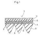
- Fig.1 is a sectional view showing an embodiment of a V-ribbed belt of this invention.
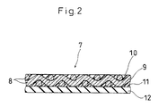
- Fig.2 is an enlarged sectional view of a canvas-rubber complex used for the above V-ribbed belt.
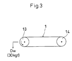
- Fig.3 is a diagram showing a layout of each pulley used for conducting an abrasion test of the back of the V-ribbed belt.
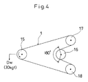
- Fig.4 is a diagram showing a layout of each pulley used for measuring transmission performance of the back of the V-ribbed belt.
- Fig.1 shows an embodiment of a V-ribbed belt 1 of this invention.
- the V-ribbed belt 1 comprises: a tension rubber 2, a compression rubber 3, tension members 5 which are arranged between the tension rubber 2 and the compression rubber 3 so as to extend in a longitudinal direction of the belt and fixed to the rubbers 2, 3 through adhesion rubber 4.
- the compression rubber 3 has a plurality of V-grooves 6, 6, ... in the form of V in section which extend in a longitudinal direction of the belt 1.
- An upper surface of the tension rubber 2 is covered with a canvas-rubber complex 7.
- the canvas-rubber complex 7 is composed of a covering canvas 8, impregnation rubber 9 with which the covering canvas 8 is impregnated, an outer rubber layer 10 applied to a first face of the covering canvas 8 which is located at the back face's side of the V-ribbed belt, an inner rubber layer 11 applied to a second face of the covering canvas 8 which is the back of the first face, and an adhesion rubber layer 12 applied to the inner rubber layer 11.
- the outer rubber layer 10 and the inner rubber layer 11 are applied to the covering canvas 8 in order to fill the texture of the covering canvas 8.
- a fabric having high strength such as a cotton fabric is used for the covering canvas 8.
- the outer rubber layer 10 and the inner rubber layer 11 are formed of a rubber composition having excellent abrasion resistance and conductivity (e.g., a compounding example B shown in Table 3).
- the adhesion rubber layer 12 is formed of a rubber composition such as a compounding example A shown in Table 2 so as to be rigidly adhered by vulcanization to the upper surface of the tension rubber 2 of the V-ribbed belt.
- Table 2 (compounding example A) CR polymer 100 parts by weight FEF carbon (as soft carbon) 20 parts by weight silicate filler 30 parts by weight magnesium oxide 5 parts by weight stearic acid 1 parts by weight processing adjutant 3 parts by weight antioxidant 4 parts by weight vulcanization accelerator 2 parts by weight vulcanizing agent 5 parts by weight total 170 parts by weight Table 3 (compounding example B) CR polymer 100 parts by weight HAF carbon (as hard carbon) 10 to 20 parts by weight conductive carbon 30 to 40 parts by weight plasticizer 5 parts by weight stearic acid 1 parts by weight magnesium oxide 5 parts by weight processing adjutant 3 parts by weight antioxidant 4 parts by weight vulcanization accelerator 0.2 parts by weight vulcanizing agent 5 parts by weight total 163.2 to 183.2 parts by weight
- each weight of rubber calculated on the basis of the areas of the impregnation rubber 9, the outer rubber layer 10, the inner rubber layer 11 and the adhesion rubber layer 12 is a factor on which abrasion of the belt back and generation of sounds at the use of the belt are dependent.
- the impregnation rubber 9 a rubber composition having ingredients as in the compounding example B or a compounding example C of Table 4 is dissolved in organic solvent such as toluene so as to form rubber cement.
- the covering canvas 8 is immersed into the rubber cement and then squeezed.
- the covering canvas 8 is impregnated to the inside of the weft and warp yarns forming the covering canvas 8 with the rubber composition in order that its weight of the impregnation rubber 9 calculated on the basis of the area is in a range from 32 to 64 g/m 2 .
- the weight of the impregnation rubber 9 is less than 32 g/m 2 , adhesive property is lowered between the rubber and the covering canvas 8. As a result, not only the rubber cannot be sufficiently permeated inside the weft and warp yarns forming the covering canvas 8, but also influence of such as water cannot be avoided. On the contrary, in case that the weight is more than 64 g/m 2 , this affects the thickness of the covering canvas 8 thereby affecting the weight of rubber calculated on the basis of the areas of the outer rubber layer 10 and the inner rubber layer 11. Therefore, the weight of the impregnation rubber 9 is preferably in a range from 32 to 64 g/m 2 .
- Table 4 (compounding example C) CR polymer 100 parts by weight FEF carbon (as soft carbon) 5 parts by weight silicate filler 25 parts by weight magnesium oxide 7 parts by weight stearic acid 1.5 parts by weight processing adjutant 3 parts by weight antioxidant 6 parts by weight vulcanization accelerator 2 parts by weight vulcanizing agent 10 parts by weight total 159.5 parts by weight
- rubber cement so formed that a rubber composition shown in the compounding example B is dissolved in organic solvent is applied, by spreading, to the first face of the covering canvas 8 subjected to the above impregnation treatment so that its weight of the outer rubber layer 10 calculated on the basis of the area is in a range from 16 to 48 g/m 2 .
- the weight of the outer rubber layer 10 is less than 16 g/m 2 , electric resistance thereof is increased, and the effect of filling the texture of the covering canvas 8 is decreased so that printability of marks to be printed on the belt back is lowered.
- the weight of the outer rubber layer 10 is preferably set to a range from 16 to 48 g/m 2 .
- a rubber composition of the compounding example B for the inner rubber layer 11 is applied to the second face of the covering canvas 8 by spreading and then another rubber composition of the compounding example A for the adhesion rubber layer 12 is applied thereto by spreading.
- a single rubber composition of the compounding example A is applied to the second face of the covering canvas 8 by spreading at a time.
- the inner rubber layer 11 and the adhesion rubber layer 12 is so formed that the total weight thereof calculated on the basis of the areas is in a range from 112 to 176 g/m 2 .
- the total weight of the inner rubber layer 11 and the adhesion rubber layer 12 is less than 112 g/m 2 , not only sufficient effect of filling the texture of the covering canvas 8 cannot be obtained, but also there cannot be obtained sufficient adhesion effect for fixing the weft and warp yarns of the covering canvas 8 subjected to spreading treatment in order that the yarns cannot move.
- the total weight is more than 176 g/m 2 , efficiency of the spreading treatment to be conducted gradually at plural times is lowered. Therefore, the total weight of the inner rubber layer 11 and the adhesion rubber layer 12 is preferably in a range from 112 to 176 g/m 2 .
- the V-ribbed belt 1 thus obtained has excellent abrasion resistance in the back thereof, so that the outer rubber layer 10 of the canvas-rubber complex 7 is prevented from being abraded even after the belt is used for a long time. Accordingly, abrasion of rubber and generation of sounds at the belt back are prevented. This leads to smooth belt driving.
- a fabric having high strength such as a cotton fabric is used for the covering canvas 8
- the outer rubber layer 10 is formed of a rubber composition of the compounding example B.
- the impregnation rubber 9 is formed of a rubber composition of a compounding example D shown in Table 5, in which the rubber composition of the compounding example C of Table 4 is mixed with specified adhesives (i.e., an adhesive including as main ingredient thereof resorcin or denatured material thereof and an adhesive including methylene donor as main ingredient thereof).
- the rubber composition of the compounding example A is used for the inner rubber layer 9 and the adhesion rubber layer 12.
- the canvas-rubber complex 7 is produced by using the above rubber compositions. As in the first-mentioned embodiment, the canvas-rubber complex 7 is adhered to the upper surface of the tension rubber 2 of the V-ribbed belt 1 by vulcanization to cover the tension rubber 2.
- the V-ribbed belt 1 obtained in this embodiment has excellent abrasion resistance in the back thereof, so that the outer rubber layer 10 of the canvas-rubber complex 7 is prevented from being abraded even after the belt 1 is used for a long time. Accordingly, stick of rubber to the pulley and generation of sounds of the belt back are prevented. This leads to smooth belt driving.
- the impregnation rubber 9 with which the covering canvas 8 is impregnated is compounded so as to perform excellent adhesive property in particular, thereby further increasing adhesive strength between the outer rubber layer 10 and the covering canvas 8 and adhesive strength between the inner rubber layer 11 and the covering canvas 8. Accordingly, even after the belt 1 is used for a long time, peeling does not generate between the adjacent layers of the belt 1, thereby further increasing durability of the belt 1.
- respective V-ribbed belts 1 in which the outer rubber layers 10 are each formed of a CR rubber composition including carbon based on compounding examples Z213 to Z216 are excellent especially in conductivity, as compared with a V-ribbed belt in which another kind of carbon is used or a V-ribbed belt in which an outer rubber layer is formed based on the compounding example A using silicate filler or based on the conventional compounding example.
- ranges of compounding of HAF carbon and conductive carbon are set to 10 to 20 parts by weight and 30 to 40 parts by weight, respectively.
- Table 7 shows results of abrasion test to the belt back.
- a Tabor-type abrasion tester is used.
- a grinding disc having a grindstone of Japanese Industrial Standard H-18
- a load of 500g applied to the belt back is measured.
- an abrasion amount of rubber and generation of stick to the pulley of the belt back is measured.
- V-ribbed belts of Examples 1-8 of this invention and V-ribbed belt of a conventional example are produced, and the respective V-ribbed belts are judged in relation to respective test items of electric resistance, adhesive strength between the layers of the covering canvas (unit:kg/cm), adhesive strength between the covering canvas and rubber (unit:kg/cm), an abrasion test of the belt back (method of measuring abrasion of the belt back on a table), transmission performance of the belt back, printability of mark to the belt back, and a general judgment.
- the test results is shown in Table 8.
- the adhesive strength between the layers of the covering canvas and the adhesive strength between the covering canvas and rubber are referred to as "adhesive strength: canvas-canvas” and “adhesive strength: canvas-rubber”, respectively.
- the abrasion test and the transmission performance of the belt back is carried out in the following manners.
- each of belts 1 of Examples 1-8 of this invention and the conventional example is looped between a driving pulley 13 and a driven pulley 14 which are flat pulleys of 100mm diameter, and is run by rotating the driving pulley 13 at 3500 rpm with the driving pulley 13 loaded with deadweight of 30kg.
- the condition of the belt back is checked to judge generation of stick to the pulleys and the degree of abrasion.
- each of belts 1 of Examples 1-8 of the present invention and the conventional example is looped over a driving pulley 15, a driven pulley 16 and idler pulleys 17, 18, and is run by rotating the driving pulley 16 at 3500 rpm with the driving pulley 16 loaded with deadweight of 30 kg. Then, metric horse-power PS of each belt 1 at 0.5 % slipping is measured. All the pulleys 15-18 are flat pulleys of 100mm diameter. A contact angle of the back of the belt 1 to the driven pulley 16 is 180°.
- V-ribbed belts 1 of the Examples 1-8 of this invention and the conventional example have the following structures.
- the canvas-rubber complex for covering the upper face of the tension belt of the V-ribbed belt is produced in the following manner. That is, a cotton fabric is used for the covering canvas.
- the canvas-rubber complex is formed by using a rubber composition of 30 g/m 2 according to the compounding example D as the impregnation rubber, a rubber composition of 16 g/m 2 according to the compounding example B as the outer rubber layer and a rubber composition of 111 g/m 2 according to the compounding example A as the inner rubber layer. Rubber cement as commonly used is applied to the inner rubber layer of the canvas-rubber complex. Then, and then the canvas-rubber complex is joined at the inner rubber layer to the upper face of the tension rubber of the V-ribbed belt and adhered thereto under set conditions of vulcanization.
- a cotton fabric is used for the covering canvas.
- the canvas-rubber complex is formed by using a rubber composition of 50 g/m 2 according to the compounding example D as the impregnation rubber, a rubber composition of 32 g/m 2 according to the compounding example B as the outer rubber layer and a rubber composition of 140 g/m 2 according to the compounding example A as the inner rubber layer. Rubber cement as commonly used is applied to the inner rubber layer of the canvas-rubber complex. Then, the canvas-rubber complex is joined at the inner rubber layer to the upper face of the tension rubber of the V-ribbed belt and adhered thereto under set conditions of vulcanization.
- a cotton fabric is used for the covering canvas.
- the canvas-rubber complex is formed by using a rubber composition of 64 g/m 2 according to the compounding example D as the impregnation rubber, a rubber composition of 48 g/m 2 according to the compounding example B as the outer rubber layer and a rubber composition of 165 g/m 2 according to the compounding example A as the inner rubber layer. Rubber cement as commonly used is applied to the inner rubber layer of the canvas-rubber complex. Then, the canvas-rubber complex is joined at the inner rubber layer to the upper face of the tension rubber of the V-ribbed belt and adhered thereto under set conditions of vulcanization.
- a cotton fabric is used for the covering canvas.
- the canvas-rubber complex is formed by using a rubber composition of 70 g/m 2 according to the compounding example D as the impregnation rubber, a rubber composition of 64 g/m 2 according to the compounding example B as the outer rubber layer and a rubber composition of 180 g/m 2 according to the compounding example A as the inner rubber layer. Rubber cement as commonly used is applied to the inner rubber layer of the canvas-rubber complex. Then, the canvas-rubber complex is joined at the inner rubber layer to the upper face of the tension rubber of the V-ribbed belt and adhered thereto under set conditions of vulcanization.
- a cotton fabric is used for the covering canvas.
- the canvas-rubber complex is formed by using a rubber composition of 32 g/m 2 according to the compounding example B as the impregnation rubber, a rubber composition of 16 g/m 2 according to the compounding example B as the outer rubber layer, a rubber composition of 14 g/m 2 according to the compounding example B as the inner rubber layer and a rubber composition of 110 g/m 2 according to the compounding example A as the adhesion rubber layer. Then, the obtained canvas-rubber complex is joined at the inner rubber layer to the upper face of the tension rubber of the V-ribbed belt and adhered thereto under set conditions of vulcanization.
- a cotton fabric is used for the covering canvas.
- the canvas-rubber complex is formed by using a rubber composition of 49 g/m 2 according to the compounding example B as the impregnation rubber, a rubber composition of 33 g/m 2 according to the compounding example B as the outer rubber layer, a rubber composition of 30 g/m 2 according to the compounding example B as the inner rubber layer and a rubber composition of 135 g/m 2 according to the compounding example A as the adhesion rubber layer. Then, the obtained canvas-rubber complex is joined at the inner rubber layer to the upper face of the tension rubber of the V-ribbed belt and adhered thereto under set conditions of vulcanization.
- a cotton fabric is used for the covering canvas.
- the canvas-rubber complex is formed by using a rubber composition of 65 g/m 2 according to the compounding example B as the impregnation rubber, a rubber composition of 45 g/m 2 according to the compounding example B as the outer rubber layer, a rubber composition of 44 g/m 2 according to the compounding example B as the inner rubber layer and a rubber composition of 164 g/m 2 according to the compounding example A as the adhesion rubber layer. Then, the obtained canvas-rubber complex is joined at the inner rubber layer to the upper face of the tension rubber of the V-ribbed belt and adhered thereto under set conditions of vulcanization.
- a cotton fabric is used for the covering canvas.
- the canvas-rubber complex is formed by using a rubber composition of 71 g/m 2 according to the compounding example B as the impregnation rubber, a rubber composition of 65 g/m 2 according to the compounding example B as the outer rubber layer, a rubber composition of 60 g/m 2 according to the compounding example B as the inner rubber layer and a rubber composition of 181 g/m 2 according to the compounding example A as the adhesion rubber layer. Then, the obtained canvas-rubber complex is joined at the inner rubber layer to the upper face of the tension rubber of the V-ribbed belt and adhered thereto under set conditions of vulcanization.
- the canvas-rubber complex is produced in the following manner.
- a cotton fabric is used for the covering canvas.
- the canvas-rubber complex is formed by using a rubber composition of 52 to 78 g/m 2 according to the conventional compounding example as the outer rubber layer and the same rubber composition of 182 to 208 g/m 2 as the inner rubber layer. Rubber cement as commonly used is applied to the inner rubber layer of the canvas-rubber complex. Then, the canvas-rubber complex is joined at the inner rubber layer to the upper face of the tension rubber of the V-ribbed belt and adhered thereto under set conditions of vulcanization. The impregnation rubber is not used in the conventional example.
Landscapes
- Engineering & Computer Science (AREA)
- General Engineering & Computer Science (AREA)
- Mechanical Engineering (AREA)
- Compositions Of Macromolecular Compounds (AREA)
- Laminated Bodies (AREA)
Claims (11)
- Un complexe toile-caoutchouc convenant pour former le dos d'une courroie à nervures en V (1), comprenant :une toile de recouvrement (8) ;un caoutchouc d'imprégnation (9) avec lequel la toile de recouvrement (8) est imprégnée ;une couche de caoutchouc externe (10) qui est appliquée à une première face de la toile de recouvrement (8) qui est située du côté de la face dorsale de la courroie à nervures en V (1) ; etune couche de caoutchouc interne (11) qui est appliquée à une seconde face de la toile de recouvrement (8) qui est l'envers de la première face,caractérisé en ce que :une couche de caoutchouc d'adhérence (12) est disposée sur la couche de caoutchouc interne (11) pour faire adhérer le complexe toile-caoutchouc (7) à la face supérieure d'un caoutchouc de tension de la courroie à nervures en V (1) ; etparmi les éléments de caoutchouc à l'exception de la couche de caoutchouc d'adhérence, au moins la couche de caoutchouc externe (10) est formée d'une composition de caoutchouc ayant une grande résistance à l'abrasion et une grande conductivité électrique.
- Le complexe toile-caoutchouc selon la revendication 1, dans lequel la couche de caoutchouc externe (10) est formée d'une composition de caoutchouc dont les principaux ingrédients sont un caoutchouc polychloroprène, du carbone dur et du carbone conducteur.
- Le complexe toile-caoutchouc selon la revendication 1, dans lequel la couche de caoutchouc externe (10), la couche de caoutchouc interne (11) et le caoutchouc d'imprégnation (9) sont chacun formés d'une composition de caoutchouc dont les principaux ingrédients sont un caoutchouc polychloroprène, du carbone dur et du carbone conducteur; et
la couche de caoutchouc d'adhérence (12) est formée d'une composition de caoutchouc dont les principaux ingrédients sont un caoutchouc polychloroprène, du carbone tendre et une charge de silicate. - Le complexe toile-caoutchouc selon la revendication 1, dans lequel la couche de caoutchouc externe (10) est formée d'une composition de caoutchouc dont les principaux ingrédients sont un caoutchouc polychloroprène, du carbone dur et du carbone conducteur ;la couche d'imprégnation (9) est formée d'une composition de caoutchouc dont les principaux ingrédients sont un caoutchouc polychloroprène et une charge de silicate ; etchacune de la couche de caoutchouc interne (11) et de la couche de caoutchouc d'adhérence est formée d'une composition de caoutchouc dont les principaux ingrédients sont un caoutchouc polychloroprène, du carbone tendre et une charge de silicate.
- Une courroie à nervures en V (1) qui comporte un caoutchouc de tension (2), un caoutchouc de compression (3) et des éléments de tension (5) qui sont disposés entre le caoutchouc de tension (2) et le caoutchouc de compression (3) de manière à s'étendre dans la direction longitudinale de la courroie (1) et fixés au caoutchouc de tension (2) et au caoutchouc de compression par un caoutchouc d'adhérence (4), le caoutchouc de compression (3) comportant plusieurs rainures (6) à section en forme de V qui s'étendent dans la direction longitudinale de la courroie (1), le caoutchouc de tension (2) étant recouvert sur sa face supérieure d'un complexe toile-caoutchouc ;le complexe toile-caoutchouc comprenant :une toile de recouvrement (8) ;un caoutchouc d'imprégnation (9) avec lequel la toile de recouvrement (8) est imprégnée ;une couche de caoutchouc externe (10) qui est appliquée à une première face de la toile de recouvrement qui est située du côté de la face dorsale de la courroie à nervures en V (1) ; etune couche de caoutchouc interne (11) qui est appliquée à une seconde face de la toile de recouvrement qui est l'envers de la première face,caractérisée en ce que :une couche de caoutchouc d'adhérence (12) est disposée sur la couche de caoutchouc interne (11) pour faire adhérer le complexe toile-caoutchouc à la face supérieure du caoutchouc de tension de la courroie à nervures en V (1) ; etparmi les éléments de caoutchouc à l'exception de la couche de caoutchouc d'adhérence, au moins la couche de caoutchouc externe (10) est formée d'une composition de caoutchouc ayant une grande résistance à l'abrasion et une grande conductivité électrique.
- La courroie à nervures en V selon la revendication 5, dans laquelle la couche de caoutchouc externe (10) est formée d'une composition de caoutchouc dont les principaux ingrédients sont un caoutchouc polychloroprène, du carbone dur et du carbone conducteur.
- La courroie à nervures en V (1) selon la revendication 5, dans laquelle la couche de caoutchouc externe (10), la couche de caoutchouc interne (11) et le caoutchouc d'imprégnation (9) sont chacun formés d'une composition de caoutchouc dont les principaux ingrédients sont un caoutchouc polychloroprène, du carbone dur et du carbone conducteur; et
la couche de caoutchouc d'adhérence (12) est formée d'une composition de caoutchouc dont les principaux ingrédients sont un caoutchouc polychloroprène, du carbone tendre et une charge de silicate. - La courroie à nervures en V (1) selon la revendication 5, dans laquelle la couche de caoutchouc externe (10) est formée d'une composition de caoutchouc dont les principaux ingrédients sont un caoutchouc polychloroprène, du carbone dur et du carbone conducteur ;la couche d'imprégnation (9) est formée d'une composition de caoutchouc dont les principaux ingrédients sont un caoutchouc polychloroprène, et une charge de silicate ; etchacune de la couche de caoutchouc interne (11) et de la couche de caoutchouc d'adhérence (12) est formée d'une composition de caoutchouc dont les principaux ingrédients sont un caoutchouc polychloroprène, du carbone tendre et une charge de silicate.
- La courroie à nervures en V (1) selon la revendication 8, dans laquelle le poids du caoutchouc d'imprégnation (9) est dans l'intervalle de 32 à 64 g/m2 ;le poids de la couche de caoutchouc externe (10) est dans l'intervalle de 16 à 48 g/m2 ; etle poids total de la couche de caoutchouc interne (11) et de la couche de caoutchouc d'adhérence (12) est dans l'intervalle de 112 à 176 g/m2.
- Un procédé de production d'une courroie à nervures en V (1) qui comporte un caoutchouc de tension (2), un caoutchouc de compression (3) et des éléments de tension (5) qui sont disposés entre le caoutchouc de tension (2) et le caoutchouc de compression (3) de manière à s'étendre dans la direction longitudinale de la courroie (1) et fixés au caoutchouc de tension (2) et au caoutchouc de compression (3) par un caoutchouc d'adhérence (4), le caoutchouc de compression (3) comportant plusieurs rainures (6) à section en forme de V qui s'étendent dans la direction longitudinale de la courroie (1), et le caoutchouc de tension (2) étant recouvert sur sa face supérieure d'un complexe toile-caoutchouc formé d'une toile de recouvrement (8) et de caoutchouc,
ledit procédé comprenant les étapes suivantes :a) plonger la toile de recouvrement (8) dans un enduit de caoutchouc pour imprégner la toile de recouvrement (8) avec la composition de caoutchouc ; etb) former une couche de caoutchouc externe (10) et une couche de caoutchouc interne (11) en appliquant un enduit de caoutchouc à une première face de la toile de recouvrement (8) qui est située du côté de la face dorsale de la courroie à nervures en V (1) et à une seconde face de la toile de recouvrement qui est l'envers de la première face ;caractérisé par les étapes supplémentaires suivante :c) former une couche de caoutchouc d'adhérence (12) en appliquant, à la couche de caoutchouc externe (10), un enduit de caoutchouc formé à partir d'une composition de caoutchouc dont les principaux ingrédients sont un caoutchouc polychloroprène, du carbone tendre et une charge de silicate, dissous dans un solvant organique, pour former ainsi le complexe toile-caoutchouc ; etd) faire adhérer par vulcanisation le complexe toile-caoutchouc au caoutchouc de tension (2) au moyen de la couche de caoutchouc d'adhérence ; et l'utilisation dans les étapes a) et b) d'un enduit de caoutchouc dont les principaux ingrédients sont un caoutchouc polychloroprène, du carbone dur et du carbone conducteur dissous dans un solvant organique. - Un procédé de production d'une courroie à nervures en V (1) qui comporte un caoutchouc de tension (2), un caoutchouc de compression (3) et des éléments de tension (5) qui sont disposés entre le caoutchouc de tension (2) et le caoutchouc de compression (3) de manière à s'étendre dans la direction longitudinale de la courroie (1) et fixés au caoutchouc de tension (2) et au caoutchouc de compression (3) par un caoutchouc d'adhérence (4), le caoutchouc de compression (3) comportant plusieurs rainures (6) à section en forme de V qui s'étendent dans la direction longitudinale de la courroie (1), et le caoutchouc de tension (2) étant recouvert sur sa face supérieure d'un complexe toile-caoutchouc formé d'une toile de recouvrement (8) et de caoutchouc,
ledit procédé comprenant les étapes suivantes :a) plonger la toile de recouvrement (8) dans un enduit de caoutchouc dissous dans un solvant organique pour imprégner la toile de recouvrement (8) avec la composition de caoutchouc ; etb) former une couche de caoutchouc externe (10) en appliquant un enduit de caoutchouc dissous dans un solvant organique à une première face de la toile de recouvrement qui est située du côté de la face dorsale de la courroie à nervures en V (1) ;caractérisé par les étapes supplémentaires suivantes :c) former une couche de caoutchouc interne (11) et une couche de caoutchouc d'adhérence (12) en appliquant un enduit de caoutchouc dont les principaux ingrédients sont un caoutchouc polychloroprène, du carbone tendre et une charge de silicate dissous dans un solvant organique à une seconde face de la toile de recouvrement (8) qui est l'envers de la première face, pour former ainsi le complexe toile-caoutchouc ; etd) faire adhérer par vulcanisation le complexe toile-caoutchouc au caoutchouc de tension (2) au moyen de la couche de caoutchouc d'adhérence (12) ; et l'utilisation dans l'étape a) d'un enduit de caoutchouc dont les principaux ingrédients sont un caoutchouc polychloroprène et une charge de silicate et l'utilisation dans l'étape b) d'un enduit de caoutchouc dont les principaux ingrédients sont un caoutchouc polychloroprène, du carbone dur et du carbone conducteur.
Applications Claiming Priority (2)
| Application Number | Priority Date | Filing Date | Title |
|---|---|---|---|
| JP5108982A JPH07117123B2 (ja) | 1993-05-11 | 1993-05-11 | Vリブドベルト |
| JP108982/93 | 1993-05-11 |
Publications (2)
| Publication Number | Publication Date |
|---|---|
| EP0624738A1 EP0624738A1 (fr) | 1994-11-17 |
| EP0624738B1 true EP0624738B1 (fr) | 1997-07-30 |
Family
ID=14498588
Family Applications (1)
| Application Number | Title | Priority Date | Filing Date |
|---|---|---|---|
| EP94303315A Expired - Lifetime EP0624738B1 (fr) | 1993-05-11 | 1994-05-09 | Complexe tissu-caoutchouc, courroie à nervures en V l'utilisant et méthode de fabrication d'une courroie à nervures en V |
Country Status (5)
| Country | Link |
|---|---|
| US (1) | US5417619A (fr) |
| EP (1) | EP0624738B1 (fr) |
| JP (1) | JPH07117123B2 (fr) |
| CA (1) | CA2122939C (fr) |
| DE (1) | DE69404547T2 (fr) |
Families Citing this family (22)
| Publication number | Priority date | Publication date | Assignee | Title |
|---|---|---|---|---|
| JP2740452B2 (ja) * | 1994-02-04 | 1998-04-15 | 株式会社椿本チエイン | 歯付きベルト及びその製造方法 |
| JP2942459B2 (ja) * | 1994-04-21 | 1999-08-30 | 株式会社椿本チエイン | 歯付きベルト |
| JP3025418B2 (ja) * | 1995-05-11 | 2000-03-27 | バンドー化学株式会社 | 伝動ベルト及びその製造方法 |
| EP0819741A3 (fr) * | 1996-07-16 | 1998-10-21 | Bridgestone Corporation | Solution de caoutchouc conducteur de l'électricité et son utilisation dans les pneumatiques |
| JPH10120137A (ja) * | 1996-10-21 | 1998-05-12 | Mitsuboshi Belting Ltd | 搬送用ベルトおよび同ベルトの製造方法 |
| AU3114599A (en) * | 1999-03-26 | 2000-10-16 | Goodyear Tire And Rubber Company, The | Electrically conductive timing belt |
| US6770004B1 (en) | 1999-03-26 | 2004-08-03 | The Goodyear Tire & Rubber Company | Electrically conductive timing belt |
| JP3474808B2 (ja) * | 1999-08-19 | 2003-12-08 | バンドー化学株式会社 | 摩擦伝動ベルトの伝動能力評価方法及びベルト伝動装置の設計支援方法 |
| CA2330648A1 (fr) | 1999-10-05 | 2001-04-05 | Caterpillar Commercial Sarl | Systeme de reglage de pelle a benne trainante |
| JP2001262483A (ja) * | 2000-03-13 | 2001-09-26 | Ichikawa Woolen Textile Co Ltd | シュープレス用ベルト |
| US6672983B2 (en) | 2000-12-21 | 2004-01-06 | The Goodyear Tire & Rubber Company | Power transmission drive system |
| CN101238176B (zh) * | 2005-08-05 | 2011-09-28 | 邦多化学株式会社 | 传动带用橡胶组合物以及传动带 |
| EP2105460B1 (fr) | 2006-12-22 | 2016-10-12 | Bando Chemical Industries Ltd. | Composition de caoutchouc pour une courroie de transmission et courroie de transmission |
| US7621114B1 (en) * | 2008-07-17 | 2009-11-24 | Fenner U.S., Inc. | Reinforced belt having reduced electrical resistivity and method for producing same |
| US7950213B2 (en) * | 2008-07-17 | 2011-05-31 | Fenner U.S., Inc. | Reinforced belt having reduced electrical resistivity and method for producing same |
| US8192316B2 (en) * | 2009-02-03 | 2012-06-05 | The Gates Corporation | Belt with wear-resistant anti-static fabric |
| DE102011114918A1 (de) * | 2011-10-06 | 2013-04-11 | Arntz Beteiligungs Gmbh & Co. Kg | Keilrippenriemen und Verfahren zu dessen Herstellung |
| US9829066B2 (en) | 2014-04-07 | 2017-11-28 | Gates Corporation | Electrically conductive power transmission belt |
| WO2019018068A1 (fr) | 2017-07-19 | 2019-01-24 | The Timken Company | Ceinture électroconductrice |
| CN110799770B (zh) * | 2017-07-19 | 2020-09-01 | 阪东化学株式会社 | 传动带及其制造方法 |
| JP6626226B2 (ja) * | 2018-02-15 | 2019-12-25 | 三ツ星ベルト株式会社 | Vリブドベルトおよびその使用方法 |
| WO2021145348A1 (fr) * | 2020-01-16 | 2021-07-22 | 三ツ星ベルト株式会社 | Fil central pour courroie d'entraînement, courroie d'entraînement, et procédé de fabrication de fil central et de courroie d'entraînement |
Family Cites Families (9)
| Publication number | Priority date | Publication date | Assignee | Title |
|---|---|---|---|---|
| US3563103A (en) * | 1969-04-18 | 1971-02-16 | Uniroyal Inc | Transmission belt |
| US4031761A (en) * | 1975-02-20 | 1977-06-28 | Dayco Corporation | Engine power take-off system with single belt drive |
| DE2715199A1 (de) * | 1976-04-08 | 1977-10-13 | Dayco Corp | Endloser transmissionsriemen |
| JPS6136534A (ja) * | 1984-07-26 | 1986-02-21 | Mitsuboshi Belting Ltd | Vリブドベルト |
| JPS61136036A (ja) * | 1984-11-30 | 1986-06-23 | Nitta Kk | デイスクドライブ用平ベルト |
| JPH0511402Y2 (fr) * | 1985-04-01 | 1993-03-22 | ||
| JP2604443B2 (ja) * | 1988-03-31 | 1997-04-30 | バンドー化学株式会社 | 伝動ベルトおよびその製造方法 |
| JPH071054B2 (ja) * | 1990-04-24 | 1995-01-11 | 三ツ星ベルト株式会社 | 歯付ベルト |
| US5232400A (en) * | 1991-09-26 | 1993-08-03 | E. I. Du Pont De Nemours And Company | Connector device |
-
1993
- 1993-05-11 JP JP5108982A patent/JPH07117123B2/ja not_active Expired - Fee Related
-
1994
- 1994-05-05 CA CA002122939A patent/CA2122939C/fr not_active Expired - Fee Related
- 1994-05-05 US US08/238,691 patent/US5417619A/en not_active Expired - Fee Related
- 1994-05-09 EP EP94303315A patent/EP0624738B1/fr not_active Expired - Lifetime
- 1994-05-09 DE DE69404547T patent/DE69404547T2/de not_active Expired - Fee Related
Also Published As
| Publication number | Publication date |
|---|---|
| CA2122939C (fr) | 1997-09-16 |
| JPH06323368A (ja) | 1994-11-25 |
| DE69404547D1 (de) | 1997-09-04 |
| CA2122939A1 (fr) | 1994-11-12 |
| DE69404547T2 (de) | 1998-03-19 |
| JPH07117123B2 (ja) | 1995-12-18 |
| EP0624738A1 (fr) | 1994-11-17 |
| US5417619A (en) | 1995-05-23 |
Similar Documents
| Publication | Publication Date | Title |
|---|---|---|
| EP0624738A1 (fr) | Complexe tissu-caoutchouc, courroie à nervures en V l'utilisant et méthode de fabrication d'une courroie à nervures en V | |
| CA2319739C (fr) | Courroie de transmission d'energie | |
| CN1128945C (zh) | 耐磨皮带及其制造方法 | |
| US6875144B2 (en) | Rubber composition, a method of making the rubber composition, a power transmission belt made from the rubber composition and a method of making the power transmission belt | |
| US5860883A (en) | Power transmission belt | |
| DE112007000568B4 (de) | Treibriemen, Verfahren zum Herstellen eines Treibriemens | |
| US6056656A (en) | V-ribbed belt | |
| US9353827B2 (en) | Toothed belt | |
| US6764422B2 (en) | Method of bonding an ethylene•α-olefin rubber composition and a fiber and a power transmission belt made using the method | |
| EP2449284B1 (fr) | Courroie crantée et son utilisation dans l'huile | |
| KR101598509B1 (ko) | 마찰전동벨트 | |
| EP2784346A1 (fr) | Courroie de transmission | |
| US20020132692A1 (en) | Low growth power transmission belt | |
| EP0892007B1 (fr) | Fibre traitée pour adhérer à une composition de caoutchouc et courroie de transmission incorporant la fibre ainsi traitée | |
| JP2001032887A (ja) | ゴムベルト | |
| US6177202B1 (en) | Power transmission belt | |
| EP0451983A2 (fr) | Courroie de transmission | |
| EP0204545B1 (fr) | Courroie de transmission | |
| JP3403938B2 (ja) | ゴム組成物およびこれを用いた伝動ベルト | |
| JP2003012871A (ja) | 短繊維含有ゴム組成物及びこれを用いた動力伝動用ベルト | |
| JP4416060B2 (ja) | 動力伝動用ベルト | |
| US20230057811A1 (en) | Synchronous belt fabric treatment and belt | |
| JPH111577A (ja) | 補強用短繊維含有ゴム組成物及びこれを用いた伝動ベルト | |
| JP2001279024A (ja) | 補強用短繊維含有ゴム組成物及びこれを用いた伝動ベルト | |
| JP2001343050A (ja) | 動力伝動用ベルト |
Legal Events
| Date | Code | Title | Description |
|---|---|---|---|
| PUAI | Public reference made under article 153(3) epc to a published international application that has entered the european phase |
Free format text: ORIGINAL CODE: 0009012 |
|
| AK | Designated contracting states |
Kind code of ref document: A1 Designated state(s): DE FR GB |
|
| 17P | Request for examination filed |
Effective date: 19950315 |
|
| 17Q | First examination report despatched |
Effective date: 19960326 |
|
| GRAG | Despatch of communication of intention to grant |
Free format text: ORIGINAL CODE: EPIDOS AGRA |
|
| GRAH | Despatch of communication of intention to grant a patent |
Free format text: ORIGINAL CODE: EPIDOS IGRA |
|
| GRAH | Despatch of communication of intention to grant a patent |
Free format text: ORIGINAL CODE: EPIDOS IGRA |
|
| GRAA | (expected) grant |
Free format text: ORIGINAL CODE: 0009210 |
|
| AK | Designated contracting states |
Kind code of ref document: B1 Designated state(s): DE FR GB |
|
| REF | Corresponds to: |
Ref document number: 69404547 Country of ref document: DE Date of ref document: 19970904 |
|
| ET | Fr: translation filed | ||
| PLBE | No opposition filed within time limit |
Free format text: ORIGINAL CODE: 0009261 |
|
| STAA | Information on the status of an ep patent application or granted ep patent |
Free format text: STATUS: NO OPPOSITION FILED WITHIN TIME LIMIT |
|
| 26N | No opposition filed | ||
| REG | Reference to a national code |
Ref country code: GB Ref legal event code: IF02 |
|
| PGFP | Annual fee paid to national office [announced via postgrant information from national office to epo] |
Ref country code: GB Payment date: 20020508 Year of fee payment: 9 |
|
| PG25 | Lapsed in a contracting state [announced via postgrant information from national office to epo] |
Ref country code: GB Free format text: LAPSE BECAUSE OF NON-PAYMENT OF DUE FEES Effective date: 20030509 |
|
| GBPC | Gb: european patent ceased through non-payment of renewal fee |
Effective date: 20030509 |
|
| PGFP | Annual fee paid to national office [announced via postgrant information from national office to epo] |
Ref country code: FR Payment date: 20040510 Year of fee payment: 11 |
|
| PG25 | Lapsed in a contracting state [announced via postgrant information from national office to epo] |
Ref country code: FR Free format text: LAPSE BECAUSE OF NON-PAYMENT OF DUE FEES Effective date: 20060131 |
|
| REG | Reference to a national code |
Ref country code: FR Ref legal event code: ST Effective date: 20060131 |
|
| PGFP | Annual fee paid to national office [announced via postgrant information from national office to epo] |
Ref country code: DE Payment date: 20070503 Year of fee payment: 14 |
|
| PG25 | Lapsed in a contracting state [announced via postgrant information from national office to epo] |
Ref country code: DE Free format text: LAPSE BECAUSE OF NON-PAYMENT OF DUE FEES Effective date: 20081202 |