EP0624742A1 - Passage d'arbre avec joint à fluide de barrage - Google Patents
Passage d'arbre avec joint à fluide de barrage Download PDFInfo
- Publication number
- EP0624742A1 EP0624742A1 EP94106396A EP94106396A EP0624742A1 EP 0624742 A1 EP0624742 A1 EP 0624742A1 EP 94106396 A EP94106396 A EP 94106396A EP 94106396 A EP94106396 A EP 94106396A EP 0624742 A1 EP0624742 A1 EP 0624742A1
- Authority
- EP
- European Patent Office
- Prior art keywords
- piston
- storage container
- shaft
- reservoir
- level
- Prior art date
- Legal status (The legal status is an assumption and is not a legal conclusion. Google has not performed a legal analysis and makes no representation as to the accuracy of the status listed.)
- Withdrawn
Links
- 230000004888 barrier function Effects 0.000 title claims abstract description 18
- 238000007789 sealing Methods 0.000 title claims abstract description 16
- 239000012530 fluid Substances 0.000 title abstract 4
- 239000007788 liquid Substances 0.000 claims abstract description 25
- 239000012528 membrane Substances 0.000 claims description 10
- 230000002950 deficient Effects 0.000 abstract 1
- 210000004907 gland Anatomy 0.000 abstract 1
- 229920002635 polyurethane Polymers 0.000 description 2
- 239000004814 polyurethane Substances 0.000 description 2
- 229920001973 fluoroelastomer Polymers 0.000 description 1
- 239000012948 isocyanate Substances 0.000 description 1
- 150000002513 isocyanates Chemical class 0.000 description 1
- 238000004519 manufacturing process Methods 0.000 description 1
- 230000003287 optical effect Effects 0.000 description 1
- 229920005862 polyol Polymers 0.000 description 1
- 150000003077 polyols Chemical class 0.000 description 1
- 230000000630 rising effect Effects 0.000 description 1
- 230000011664 signaling Effects 0.000 description 1
- 229920002379 silicone rubber Polymers 0.000 description 1
- 239000004945 silicone rubber Substances 0.000 description 1
- 238000003466 welding Methods 0.000 description 1
Images

Classifications
-
- F—MECHANICAL ENGINEERING; LIGHTING; HEATING; WEAPONS; BLASTING
- F16—ENGINEERING ELEMENTS AND UNITS; GENERAL MEASURES FOR PRODUCING AND MAINTAINING EFFECTIVE FUNCTIONING OF MACHINES OR INSTALLATIONS; THERMAL INSULATION IN GENERAL
- F16J—PISTONS; CYLINDERS; SEALINGS
- F16J15/00—Sealings
- F16J15/16—Sealings between relatively-moving surfaces
- F16J15/166—Sealings between relatively-moving surfaces with means to prevent the extrusion of the packing
-
- F—MECHANICAL ENGINEERING; LIGHTING; HEATING; WEAPONS; BLASTING
- F04—POSITIVE - DISPLACEMENT MACHINES FOR LIQUIDS; PUMPS FOR LIQUIDS OR ELASTIC FLUIDS
- F04D—NON-POSITIVE-DISPLACEMENT PUMPS
- F04D15/00—Control, e.g. regulation, of pumps, pumping installations or systems
- F04D15/02—Stopping of pumps, or operating valves, on occurrence of unwanted conditions
- F04D15/0245—Stopping of pumps, or operating valves, on occurrence of unwanted conditions responsive to a condition of the pump
- F04D15/0263—Stopping of pumps, or operating valves, on occurrence of unwanted conditions responsive to a condition of the pump the condition being temperature, ingress of humidity or leakage
-
- F—MECHANICAL ENGINEERING; LIGHTING; HEATING; WEAPONS; BLASTING
- F04—POSITIVE - DISPLACEMENT MACHINES FOR LIQUIDS; PUMPS FOR LIQUIDS OR ELASTIC FLUIDS
- F04D—NON-POSITIVE-DISPLACEMENT PUMPS
- F04D29/00—Details, component parts, or accessories
- F04D29/08—Sealings
- F04D29/10—Shaft sealings
- F04D29/106—Shaft sealings especially adapted for liquid pumps
- F04D29/108—Shaft sealings especially adapted for liquid pumps the sealing fluid being other than the working liquid or being the working liquid treated
-
- G—PHYSICS
- G01—MEASURING; TESTING
- G01F—MEASURING VOLUME, VOLUME FLOW, MASS FLOW OR LIQUID LEVEL; METERING BY VOLUME
- G01F23/00—Indicating or measuring liquid level or level of fluent solid material, e.g. indicating in terms of volume or indicating by means of an alarm
- G01F23/30—Indicating or measuring liquid level or level of fluent solid material, e.g. indicating in terms of volume or indicating by means of an alarm by floats
- G01F23/56—Indicating or measuring liquid level or level of fluent solid material, e.g. indicating in terms of volume or indicating by means of an alarm by floats using elements rigidly fixed to, and rectilinearly moving with, the floats as transmission elements
- G01F23/60—Indicating or measuring liquid level or level of fluent solid material, e.g. indicating in terms of volume or indicating by means of an alarm by floats using elements rigidly fixed to, and rectilinearly moving with, the floats as transmission elements using electrically actuated indicating means
-
- G—PHYSICS
- G01—MEASURING; TESTING
- G01F—MEASURING VOLUME, VOLUME FLOW, MASS FLOW OR LIQUID LEVEL; METERING BY VOLUME
- G01F23/00—Indicating or measuring liquid level or level of fluent solid material, e.g. indicating in terms of volume or indicating by means of an alarm
- G01F23/30—Indicating or measuring liquid level or level of fluent solid material, e.g. indicating in terms of volume or indicating by means of an alarm by floats
- G01F23/76—Indicating or measuring liquid level or level of fluent solid material, e.g. indicating in terms of volume or indicating by means of an alarm by floats characterised by the construction of the float
Definitions
- the invention relates to a shaft bushing, consisting of two shaft seals arranged in a housing-like chamber surrounding the shaft, between which a space filled with sealing liquid is left, from which a connecting line leads to a storage container arranged above the level of the chamber.
- shaft feedthroughs have to be sealed against critical media, such as pumps, which have to promote the reaction components polyol and isocyanate in the production of polyurethane.
- the barrier liquid is intended to prevent the critical medium from escaping outdoors.
- the storage container usually has a transparent wall so that you can see the level. A sudden increase or decrease in the level indicates a damaged seal. Such reservoirs cannot be observed continuously, however, and leaks that are not recognized in time can cause considerable damage.
- This object is achieved in that the surface of the barrier liquid contained in the reservoir is covered by a piston which interacts outside the reservoir with an associated signal transmitter, the target fill level of the barrier liquid being matched to the signal transmitter.
- Such signal transmitters available on the market generally have an upper and a lower limit contact, which cooperate with a closing contact which can be actuated directly by the piston or via a plunger.
- a closing contact When the closing contact is actuated, a circuit is closed and, depending on the type of signal generator, it gives an optical and / or acoustic alarm.
- the piston must seal against the wall of the storage container and that there must be no air between the piston and the surface of the sealing liquid, because this would distort the signaling due to its compressibility. Rising and falling levels indicate a leak in the reservoir.
- the barrier liquid is normally under atmospheric pressure.
- a membrane, on which the piston rests is arranged between the piston and the surface of the sealing liquid, hermetically sealing against the wall of the storage container and movable by changing the fill level.
- the membrane consists, for example, of an elastic polyurethane or of fluororubber and is preferably clamped in a sealing manner between a base part and a cover part of the storage container.
- the diameter of the piston is smaller than the inside diameter of the storage container, and the membrane forms a fold between the rim of the piston and the inner wall of the container, the height of which changes with the change in level changes.
- the storage container must not be completely filled at the desired fill level, but that at least as much space or free height must be present above the sealing liquid that the upper limit contact can respond when the fill level rises.
- the piston and membrane are preferably firmly connected.
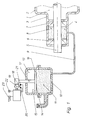
- the shaft bushing sealing against the interior 1 of a pump 2 consists of a chamber 4 arranged in the pump housing 3, in which two lip seals 6, 7 surrounding a shaft 5 are arranged are, between which a space 8 filled with sealing liquid is left.
- This is connected via a connecting line 9 to a storage container 10 arranged above the level of the chamber 4.
- barrier liquid 11 In the reservoir 10 there is barrier liquid 11, the nominal level of which is matched to a signal transmitter 12.
- a free space 13 in which there is a piston 16 covering the surface 14 of the barrier liquid 11 and sealingly sealing against the wall 15.
- the piston 16 is equipped with a plunger 17 which leads out of the reservoir 10 and which interacts with a wheel 19 of the signal transmitter 12 which has a make contact 18 and which has limit contacts 20, 21 which can be actuated with the make contact 18.
- the target fill level of the barrier liquid 11 in the reservoir 10 is set so that the make contact 18 is at the same distance from the two limit contacts 20, 21.
- the limit contact 20 is closed and when the fill level rises, the limit contact 21 is closed, whereby an alarm lamp 22 and an acoustic warning device 23 are actuated.
- the shaft bushing sealing against the interior 31 of a pump 32 consists of a chamber 34 arranged in the pump housing 33, in which two lip seals 36, 37 surrounding a shaft 35 are arranged, between which a space 38 filled with sealing liquid is left.
- This is connected via a connecting line 39 to a storage container 40 arranged above the level of the chamber 34.
- barrier liquid 41 In the reservoir 40 there is barrier liquid 41, the nominal level of which is matched to a signal transmitter 42.
- barrier liquid 41 There is a free space 43 above the barrier liquid 41, in which a piston 46 is arranged. Between the piston 46 and the surface 44 The barrier liquid 41 has a membrane 54 made of silicone rubber covering the surface 44 of the barrier liquid 41, which is clamped hermetically in the reservoir.
- the piston 46 in this embodiment has a smaller diameter than the inside diameter of the storage container 40, and the mobility of the membrane is made possible by the fact that it forms a fold 55 extending into the space 43 between the piston 46 and the wall 45. So that the simultaneous movement of piston 46 and membrane 54 is ensured, both are firmly connected to one another by welding.
- the piston 46 is equipped with a plunger 47 which leads out of the reservoir 40 and which interacts with a wheel 49 of the signal transmitter 42 which has a make contact 48 and which has limit contacts 50, 51 which can be actuated by the make contact 48.
- the target level of the barrier liquid 41 in the reservoir 40 is set so that the make contact 48 is at the same distance from the two limit contacts 50, 51. When the fill level drops, the limit contact 50 is closed and when the fill level rises, the limit contact 51 is closed, as a result of which an alarm lamp 52 and an acoustic warning device 53 are actuated.
Landscapes
- Engineering & Computer Science (AREA)
- General Engineering & Computer Science (AREA)
- Mechanical Engineering (AREA)
- Physics & Mathematics (AREA)
- Fluid Mechanics (AREA)
- General Physics & Mathematics (AREA)
- Sealing Devices (AREA)
- Infusion, Injection, And Reservoir Apparatuses (AREA)
- Measurement Of Levels Of Liquids Or Fluent Solid Materials (AREA)
Applications Claiming Priority (2)
| Application Number | Priority Date | Filing Date | Title |
|---|---|---|---|
| DE9307024U DE9307024U1 (de) | 1993-05-08 | 1993-05-08 | Wellendurchführung mit Sperrflüssigkeitsabdichtung |
| DE9307024U | 1993-05-08 |
Publications (1)
| Publication Number | Publication Date |
|---|---|
| EP0624742A1 true EP0624742A1 (fr) | 1994-11-17 |
Family
ID=6893050
Family Applications (1)
| Application Number | Title | Priority Date | Filing Date |
|---|---|---|---|
| EP94106396A Withdrawn EP0624742A1 (fr) | 1993-05-08 | 1994-04-25 | Passage d'arbre avec joint à fluide de barrage |
Country Status (3)
| Country | Link |
|---|---|
| EP (1) | EP0624742A1 (fr) |
| JP (1) | JPH06341553A (fr) |
| DE (1) | DE9307024U1 (fr) |
Cited By (4)
| Publication number | Priority date | Publication date | Assignee | Title |
|---|---|---|---|---|
| EP1104518A4 (fr) * | 1998-08-17 | 2004-12-01 | Donald Philip Arbuckle | Appareil d'etancheite integre a fluide barriere pourvu d'un indicateur visuel de volume |
| EP1625314A4 (fr) * | 2003-05-15 | 2006-05-31 | Woodward Governor Co | Agencement d'etancheite dynamique pour arbre mobile |
| WO2014181074A3 (fr) * | 2013-05-09 | 2014-12-31 | A.E.S. Engineering Ltd | Système de support de joint mécanique |
| CN111255704A (zh) * | 2018-11-30 | 2020-06-09 | 中国石油天然气集团有限公司 | 泵的保护装置及泵组件 |
Families Citing this family (1)
| Publication number | Priority date | Publication date | Assignee | Title |
|---|---|---|---|---|
| CN102954030B (zh) * | 2012-10-03 | 2014-11-19 | 车晋绥 | 带水封泵的胶泵 |
Citations (3)
| Publication number | Priority date | Publication date | Assignee | Title |
|---|---|---|---|---|
| WO1987001171A1 (fr) * | 1985-08-15 | 1987-02-26 | Vickers Plc | Organe de commande de pression pour un joint a fluide tampon |
| WO1990015273A1 (fr) * | 1989-06-01 | 1990-12-13 | William Thomson Sweeney | Amenagement de joints |
| GB2244104A (en) * | 1990-05-15 | 1991-11-20 | Flexibox Ltd | Mechanical seals |
-
1993
- 1993-05-08 DE DE9307024U patent/DE9307024U1/de not_active Expired - Lifetime
-
1994
- 1994-04-25 EP EP94106396A patent/EP0624742A1/fr not_active Withdrawn
- 1994-05-06 JP JP11603694A patent/JPH06341553A/ja active Pending
Patent Citations (3)
| Publication number | Priority date | Publication date | Assignee | Title |
|---|---|---|---|---|
| WO1987001171A1 (fr) * | 1985-08-15 | 1987-02-26 | Vickers Plc | Organe de commande de pression pour un joint a fluide tampon |
| WO1990015273A1 (fr) * | 1989-06-01 | 1990-12-13 | William Thomson Sweeney | Amenagement de joints |
| GB2244104A (en) * | 1990-05-15 | 1991-11-20 | Flexibox Ltd | Mechanical seals |
Non-Patent Citations (2)
| Title |
|---|
| G.L. TAYLOR: "DOOUBLE SEAL CIRCULANT SYSTEMS", PUMPS, POMPES, PUMPEN, no. 101, 1975, MORDEN GB, pages 601 - 606 * |
| L. DINANNO: "Experimental evaluation of rotary shaft seals for use in organic Rankine cycle engines", PROCEEDINGS OF THE NATIONAL CCONFERENCE ON FLUID POWER, vol. 26, 1972, CHICAGO, pages 60 - 77 * |
Cited By (9)
| Publication number | Priority date | Publication date | Assignee | Title |
|---|---|---|---|---|
| EP1104518A4 (fr) * | 1998-08-17 | 2004-12-01 | Donald Philip Arbuckle | Appareil d'etancheite integre a fluide barriere pourvu d'un indicateur visuel de volume |
| EP1625314A4 (fr) * | 2003-05-15 | 2006-05-31 | Woodward Governor Co | Agencement d'etancheite dynamique pour arbre mobile |
| US7118114B2 (en) | 2003-05-15 | 2006-10-10 | Woodward Governor Company | Dynamic sealing arrangement for movable shaft |
| US8074999B2 (en) | 2003-05-15 | 2011-12-13 | Woodward, Inc. | Dynamic sealing arrangement for movable shaft |
| WO2014181074A3 (fr) * | 2013-05-09 | 2014-12-31 | A.E.S. Engineering Ltd | Système de support de joint mécanique |
| CN105378352A (zh) * | 2013-05-09 | 2016-03-02 | Aes工程有限公司 | 机械密封辅助系统 |
| CN105378352B (zh) * | 2013-05-09 | 2019-06-14 | Aes工程有限公司 | 机械密封辅助系统 |
| CN111255704A (zh) * | 2018-11-30 | 2020-06-09 | 中国石油天然气集团有限公司 | 泵的保护装置及泵组件 |
| CN111255704B (zh) * | 2018-11-30 | 2021-08-31 | 中国石油天然气集团有限公司 | 泵的保护装置及泵组件 |
Also Published As
| Publication number | Publication date |
|---|---|
| DE9307024U1 (de) | 1993-07-22 |
| JPH06341553A (ja) | 1994-12-13 |
Similar Documents
| Publication | Publication Date | Title |
|---|---|---|
| EP0063685B1 (fr) | Système de mesure de niveau de liquide | |
| EP0438428B1 (fr) | Pompe a soufflet a double action | |
| EP0248821B1 (fr) | Detecteur de la pression des pneus d'un vehicule | |
| WO1998037329A1 (fr) | Accumulateur de pression | |
| DE2851070B2 (de) | Vorrichtung zum Entlasten des Dichtungspaketes einer Kolbenstange eines hydraulischen Teleskopstoßdämpfers | |
| EP0624742A1 (fr) | Passage d'arbre avec joint à fluide de barrage | |
| DE2809399B2 (de) | Bremsflüssigkeitsbehälter für den Hauptbremszylinder einer hydraulischen Bremsanlage | |
| DE2749244C3 (de) | Bremsflüssigkeitsbehälter fur den Hauptzylinder eines hydraulischen Bremssystems, insbesondere eines Kraftfahrzeug-Bremssystems | |
| DE2636607A1 (de) | Abgedichteter behaelter fuer bremsdruckzylinder | |
| DE4035447C2 (de) | Elektrodenhalterung zur Druckkompensation an elektrochemischen Meßsystemen | |
| EP1507999A1 (fr) | Reservoir de stockage pour pompe a lubrifiant | |
| DE2929442A1 (de) | Elektrohydraulisches stellgeraet | |
| DE3048651A1 (de) | "druckbehaelter, insbesondere hydropneumatischer speicher" | |
| WO2001077530A1 (fr) | Accumulateur de pression | |
| DE7425865U (de) | Druckölspeicher | |
| DE3227235C2 (fr) | ||
| DE10101856A1 (de) | Druckmittelspeicher | |
| EP0285817B1 (fr) | Dispositif transmetteur de fluides | |
| DE1019753B (de) | Abschalter fuer elektrische Kondensatoren | |
| DE2345870A1 (de) | Nachfuellbehaelter einer druckmittelbetaetigten zweikreisbremse fuer kraftfahrzeuge | |
| DE19539779A1 (de) | Speicherkammer für Bremmsflüssigkeit einer hydraulischen Fahrzeug-Bremsanlage | |
| DE3522383A1 (de) | Kompakt-differenzdruckaufnehmer | |
| DE1475782A1 (de) | Leckanzeige- und Kontrollgeraet fuer Fluessigkeitslagerbehaelter mit Sicherungseinrichtung fuer auslaufendes Lagergut | |
| DE3131517A1 (de) | Behaelter fuer aggressive fluessigkeiten | |
| DE2942016A1 (de) | Fluidpegelanzeiger |
Legal Events
| Date | Code | Title | Description |
|---|---|---|---|
| PUAI | Public reference made under article 153(3) epc to a published international application that has entered the european phase |
Free format text: ORIGINAL CODE: 0009012 |
|
| AK | Designated contracting states |
Kind code of ref document: A1 Designated state(s): DE ES FR GB IT |
|
| STAA | Information on the status of an ep patent application or granted ep patent |
Free format text: STATUS: THE APPLICATION IS DEEMED TO BE WITHDRAWN |
|
| 18D | Application deemed to be withdrawn |
Effective date: 19950518 |