EP0624830A2 - Dispositif de fixage - Google Patents
Dispositif de fixage Download PDFInfo
- Publication number
- EP0624830A2 EP0624830A2 EP94830216A EP94830216A EP0624830A2 EP 0624830 A2 EP0624830 A2 EP 0624830A2 EP 94830216 A EP94830216 A EP 94830216A EP 94830216 A EP94830216 A EP 94830216A EP 0624830 A2 EP0624830 A2 EP 0624830A2
- Authority
- EP
- European Patent Office
- Prior art keywords
- rotating member
- fixing
- largest
- recording material
- fixing device
- Prior art date
- Legal status (The legal status is an assumption and is not a legal conclusion. Google has not performed a legal analysis and makes no representation as to the accuracy of the status listed.)
- Granted
Links
Images






Classifications
-
- G—PHYSICS
- G03—PHOTOGRAPHY; CINEMATOGRAPHY; ANALOGOUS TECHNIQUES USING WAVES OTHER THAN OPTICAL WAVES; ELECTROGRAPHY; HOLOGRAPHY
- G03G—ELECTROGRAPHY; ELECTROPHOTOGRAPHY; MAGNETOGRAPHY
- G03G15/00—Apparatus for electrographic processes using a charge pattern
- G03G15/20—Apparatus for electrographic processes using a charge pattern for fixing, e.g. by using heat
- G03G15/2003—Apparatus for electrographic processes using a charge pattern for fixing, e.g. by using heat using heat
- G03G15/2014—Apparatus for electrographic processes using a charge pattern for fixing, e.g. by using heat using heat using contact heat
- G03G15/2053—Structural details of heat elements, e.g. structure of roller or belt, eddy current, induction heating
-
- G—PHYSICS
- G03—PHOTOGRAPHY; CINEMATOGRAPHY; ANALOGOUS TECHNIQUES USING WAVES OTHER THAN OPTICAL WAVES; ELECTROGRAPHY; HOLOGRAPHY
- G03G—ELECTROGRAPHY; ELECTROPHOTOGRAPHY; MAGNETOGRAPHY
- G03G15/00—Apparatus for electrographic processes using a charge pattern
- G03G15/20—Apparatus for electrographic processes using a charge pattern for fixing, e.g. by using heat
- G03G15/2003—Apparatus for electrographic processes using a charge pattern for fixing, e.g. by using heat using heat
- G03G15/2014—Apparatus for electrographic processes using a charge pattern for fixing, e.g. by using heat using heat using contact heat
- G03G15/206—Structural details or chemical composition of the pressure elements and layers thereof
-
- G—PHYSICS
- G03—PHOTOGRAPHY; CINEMATOGRAPHY; ANALOGOUS TECHNIQUES USING WAVES OTHER THAN OPTICAL WAVES; ELECTROGRAPHY; HOLOGRAPHY
- G03G—ELECTROGRAPHY; ELECTROPHOTOGRAPHY; MAGNETOGRAPHY
- G03G15/00—Apparatus for electrographic processes using a charge pattern
- G03G15/20—Apparatus for electrographic processes using a charge pattern for fixing, e.g. by using heat
- G03G15/2003—Apparatus for electrographic processes using a charge pattern for fixing, e.g. by using heat using heat
- G03G15/2014—Apparatus for electrographic processes using a charge pattern for fixing, e.g. by using heat using heat using contact heat
- G03G15/2064—Apparatus for electrographic processes using a charge pattern for fixing, e.g. by using heat using heat using contact heat combined with pressure
-
- G—PHYSICS
- G03—PHOTOGRAPHY; CINEMATOGRAPHY; ANALOGOUS TECHNIQUES USING WAVES OTHER THAN OPTICAL WAVES; ELECTROGRAPHY; HOLOGRAPHY
- G03G—ELECTROGRAPHY; ELECTROPHOTOGRAPHY; MAGNETOGRAPHY
- G03G2215/00—Apparatus for electrophotographic processes
- G03G2215/20—Details of the fixing device or porcess
- G03G2215/2003—Structural features of the fixing device
- G03G2215/2058—Shape of roller along rotational axis
- G03G2215/2061—Shape of roller along rotational axis concave
Definitions
- This invention relates to a fixing device included in an image forming apparatus which adopts an electrophotographic method, an electrostatic recording method, or the like. More particularly, the invention relates to a heating fixing device which is configured by a fixing member and a pressing member disposed in pressure contact with each other.
- heating fixing devices are widely used, in which an unfixed toner image carried on a transfer material is fixed as a permanent image by passing the transfer material through a nip portion formed by a fixing roller and a pressing roller which rotate in pressure contact with each other.
- at least one of the fixing roller and the pressing roller is generally configured in a so-called inverse-crown shape, in which the outer diameter at two end portions in the longitudinal direction has a largest value, and the outer diameter at a central portion has a smallest value.
- the roller having such a configuration forcedly stretches the transfer material in the longitudinal direction of the roller, so that two end portions of the transfer material, which is not rigid, are corrugated, thereby degrading, in some cases, the quality of the obtained image.
- a proposal has been disclosed in U.S. Patent No. 5,130,754 (Japanese Patent Laid-open Application (Kokai) No. 2-262684 (1990)), in which portions having the largest diameter of the pressing roller configured in the inverse-crown shape are positioned inside the two ends of the roller to form slight stripes at portions of the transfer material facing that portions, so that two end portions of the transfer material are strengthened.
- the hardness of the pressing roller must have a small value in order to maintain a nip width sufficient for fixing an unfixed toner image on the transfer material. In such a case, even if the shape of end portions of the pressing roller is changed as disclosed in the above-described proposal, the effect of the change is weakened, and "corrugation" is apt to be produced.
- the present invention which achieves these objectives relates to a fixing device comprising a fixing rotating member comprising a core material and a resin layer provided thereon, and a pressing rotating member comprising a rubber layer for forming a nip with the fixing rotating member.
- a fixing operation is performed by grasping and conveying a recording material carrying an unfixed image by the nip.
- the core material of the fixing rotating member has a largest-diameter portion between a central portion and each end portion within a region where a recording material of the largest size passes.
- the diameter of the core material is gradually reduced from the largest-diameter portion toward the inside and the outside.
- the outer shape of the fixing rotating member conforms to the shape of the core material.
- the present invention relates to a fixing device comprising a fixing rotating member for contacting an unfixed image, and a pressing rotating member, whose hardness is lower than the hardness of the fixing rotating member, for forming a nip with the fixing rotating member.
- a fixing operation is performed by grasping and conveying a recording material carrying the unfixed image by the nip.
- the fixing rotating member has a largest-diameter portion between a central portion and each end portion within a region where a recording material of the largest size passes.
- the diameter of the fixing rotating member is gradually reduced from the largest-diameter portion toward the inside and the outside.
- the pressing rotating member has substantially a straight shape or inverse-crown shape.
- the hardness of the pressing roller is at least 30° and equal to or less than 70°.
- the outer diameter of the fixing rotating member is equal to or less than 30 mm.
- the inclination of the fixing rotating member from the largest-diameter portion toward the outside is at least 0.02 and equal to or less than 0.2.
- the inclination of of the fixing rotating member from the largest-diameter portion toward the outside is at least 20 times and equal to or less than 300 times the inclination of the fixing rotating member from the largest-diameter portion toward the inside.
- the inclination of the fixing rotating member from the largest-diameter portion toward the outside is constant or increases toward each end portion.
- the diameter of the pressing rotating member at a portion corresponding to the neighborhood of an and of the recording material is reduced from the innside toward the outside of the end of the recording material.
- the present invention relates to a fixing rotating member for contacting an unfixed image, and a pressing rotating member for forming a nip with the fixing rotating member.
- a fixing operation is performed by grasping and conveying a recording material carrying the unfixed image by the nip.
- the diameter of the fixing rotating member is reduced from the innside toward the outside at each portion corresponding to the neighborhood of an end of each of a plurality of recording materials of different sizes.
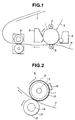
- FIG. 1 is a diagram illustrating the configuration of a principal portion of an image forming apparatus which includes a fixing device according to a first embodiment of the present invention.
- a photosensitive drum 1 comprises a photosensitive material, such as an OPC (organic photoconductor), amorphous Se, amorphous Si or the like, formed on a cylindrical base made of aluminum, nickel or the like.
- the photosensitive drum 1 is rotatably driven in the direction of the arrow.
- the surface of the photosensitive drum 1 is uniformly charged by a charging roller 2, serving as a charging device.
- scanning exposure by a laser beam 3 subjected to on-off control in accordance with image information is performed to form an electrostatic latent image.
- the electrostatic latent image is developed and visualized by a developing device 4.
- a jumping developing method, a two-component developing method, a FEED developing method or the like is used as the developing method. In many cases, image exposure and reversal development are combined.
- the visualized toner image is transferred by a transfer roller 5, serving as a transfer device, onto a transfer material P, serving as a recording material, conveyed at a predetermined timing.
- the transfer material P, on which the toner image has been transferred is conveyed to a fixing device 6, where the toner image is fixed as a permanent image. Thereafter, the transfer material P is discharged onto a sheet-discharging tray 7 in a so-called face-down state. Toner particles remaining on the photosensitive drum 1 are removed from the surface of the photosensitive drum 1 by a cleaning device 8.
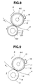
- FIG. 2 illustrates the configuration of the heating fixing device 6 of the present embodiment.
- a fixing roller 9 and a pressing roller 10 rotate in the directions of the respective arrows.
- the fixing roller 9 comprises a layer 12 of PFA, which is a fluororesin having excellent releasability, 30 ⁇ m thick coated on the surface of a hollow core bar 11, made of alluminum which has excellent heat resistance, 2 mm thick having an inner diameter of 26 mm.
- a halogen-lamp heater 13 for heating the fixing roller 9 is disposed within the hollow core bar 11.
- the hardness of the surface of the fixing roller 9 is at least 90° (measured by a JIS (Japanese Industrial Standards) A hardness meter).
- the pressing roller 10 comprises a layer 15 of silicone rubber, which has excellent releasability, 10 mm thick formed on the outer circumference of a core bar 14, made of iron, having an outer diameter of 10 mm, and has the so-called inverse-crown shape, in which the difference between the diameter at largest-diameter portions situated at two end portions in the longitudinal direction and the diameter at a smallest-diameter portion situated at a central portion equals 0.2 mm.
- the hardness of the pressing roller 10 is 50° (ASKER C hardness at a load of 500 gf).
- the fixing roller 9 and the pressing roller 10 are in pressure contact with each other by a spring (not shown) at respective two end portions in the longitudinal direction.
- a thermistor 16 for detecting the surface temperature of the fixing roller 9 contacts the fixing roller 9.
- Information relating to the surface temperature of the fixing roller 9 detected by the thermistor 16 is transmitted to a CPU (central processing unit, not shown) via an A/D (analog-to-digital) converter (not shown).
- the CPU performs on-off control of the halogen-lamp heater 13 via an AC driver (not shown), so that the surface temperature of the fixing roller 9 is controlled at a predetermined value.
- the fixing roller 9 has the inverse-crown shape, in which the outer diameter at a central portion in the longitudinal direction is smaller than the diameter at largest-diameter portions, and the largest-diameter portions are situated outside the central portion and inside the two ends in the longitudinal direction. More specifically, the outer diameter D1 at the smallest-diameter portion is 30 mm, the outer diameters D2 and D3 at the largest-diameter portions "a" equal 30.25 mm, and the outer diameters D4 and D5 at the two ends b equal 29.4 mm.
- the largest-diameter portions "a" are inside positions c where the two ends of a transfer material P having the largest width pass.
- the distance L between positions "a” and c is 4 mm.
- the positions c where the two ends of the transfer material P having the largest width pass are inside the two ends b of the fixing roller 9.
- the distance L' between positions b and c is 3 mm.
- a releasing resin layer having a substantially uniform thickness is provided on the core bar 11.
- the core bar 11 has largest-diameter portions between a central portion and the two ends within the region where the recording material having the largest width passes, and the diameters of the core bar 11 are gradually reduced from the largest-diameter portions toward the central portion and the two ends.
- the resin layer 12 provided on the core bar 11 conforms to the shape of the core bar 11.
- the fixing roller 9 has the above-described shape.
- each fixing roller was combined with pressing rollers having different hardness values, and the degree of "corrugation" produced at two end portions of a transfer material, and the mountability of sheets of the transfer material in a face-down sheet-discharging operation were evaluated.
- Table 1 shows the results of the experiments using the conventional fixing device. In Table 1, mark ⁇ indicates “excellent”, mark ⁇ indicates “pratically no problem”, and mark x indicates “inferior”.
- Table 1 indicates that when the hardness of the pressing roller is low, the effect of improving the shape of end portions of the pressing roller is canceled, causing remarkable "corrugation".
- the hardness of the pressing roller is high, a large amount of pressure and heat are supplied to two end portions of the transfer material, whereby fibers of the tranfer material are greatly stretched, inverse curl occurs in the transfer material, and therefore the mountability of sheets of the transfer material is degraded. It has become clear that when the conventional heating fixing device is used, it is difficult to prevent "corrugation" and at the same time to provide excellent mountability of sheets of the transfer material.
- Table 2 shows experimental results obtained when the heating fixing device of the present embodiment is used.
- Table 2 indicates that even if the hardness of the pressing roller is low, the occurrence of "corrugation" at two end portions of the transfer material can be prevented by providing the transfer material with appropriate stiffness. On the other hand, even if the hardness of the pressing roller is high, a large amount of pressure and heat are not supplied to two end portions of the transfer material, and the mountability of sheets of the transfer material can be improved. However, when the hardness of the pressing roller is high, stripes caused by the shape of the ends of the fixing roller are remarakably produced in the vicinity of two end portions of the transfer material, thereby degrading the quality of the obtained image.
- the hardness of the pressing roller is effective to make the hardness of the pressing roller to be equal to or less than 70°, and more preferably, to be equal to or less than 60°, in addition to improving the shape of the ends of the fixing roller as in the present embodiment.
- tension is applied to the recording material by the hard fixing roller which is resistant to deformation. Hence, the recording material can be securely regulated.
- the pressing roller 10 has an inverse-crown shape in which the outer diameter at the center in the longitudinal direction has a smallest value, and the outer diameter at the two ends has a largest value. If the pressing roller 10 has a crown shape in which the outer diameter at the two ends in the longitudinal direction has a smallest value, and the outer diamter at the center has a largest value, the transfer material conforms to the shape of the fixing roller and the like when it passes through a nip portion formed by the fixing roller and the pressing roller, so that inverse curl increases, and the mountability of sheets of the transfer material is extremely degraded. In addition, a large force exerting toward the center of the transfer material in the longitudinal direction is present.
- the pressing roller preferably has a straight shape or an inverse-crown shape.
- the function of stretching fibers on the side of a non-printed surface of the transfer material at two end portions caused by the above-described shape contributes to prevent inverse curl.
- the pressing roller preferably has a straight shape or an inverse-crown shape.
- the pressing roller has a portion which has substantially an inverse-crown shape in a state of pressure contact with the fixing roller, as shown in FIG. 6.
- the pressing roller shown in the present embodiment its two end portions are bent about 0.2 mm in a pressed state. Experments performed in such a sate have cleared that the above-described effect can be sufficiently obtained if the difference ⁇ R between the outer diameter of the pressing roller at the central portion in the longitudinal direction and the outer diameter at two end portions is equal to or less than 0.2 mm.
- the difference ⁇ R between the outer diameter of the pressing roller at the central portion in the longitudinal direction and the outer diameter at the two end portions satisfies the following expression: ⁇ R ⁇ 2 x 5wl4/6 ⁇ Ed4, where w is the load per unit length, 1 is the length of the core bar, E is Young's modulus, and d is the outer diameter of the core bar.
- the heating fixing device By configuring the heating fixing device as in the present embodiment, it is possible to totally prevent problems, such as "corrugation", stripes, inverse curl and creases, which will occur in the transfer material, and to remarkably improve the quality of the obtained image, for example, without performing large-scale improvement in the apparatus, increasing the production cost of the apparatus, and degrading the productivity of the apparatus.
- the present invention may, of course, be applied to a heating fixing device having the schematic configuration shown in FIG. 7, in which a fixed member 18 incorporating a heating member 17 is used as a heating member, a heat-resistant film 19 is conveyed between the fixed member 18 and a pressing member 10, and heat generated by the heating member 17 is supplied to a transfer material P via the heat-resistant film 19.
- FIG. 8 illustrates a heating fixing apparatus 6 used in the present embodiment.
- the present embodiment has a feature in that a fixing roller 90 is combined with a pressing roller 100 having a PFA film 30 ⁇ m thick coated on the surface layer of silicone rubber 15.
- the provision of a releasing layer such as the above-described PFA film on the surface of the presing roller is very important from the viewpoint of preventing adhesion of toner particles, paper powders and the like to the surface of the pressing roller as contamination, and increasing the life of the pressing roller without using a cleaning member.
- table 3 illustrates experimental results obtained when the fixing roller is combined with a pressing roller having no releasing layer, and a pressing roller having a releasing layer in the conventional heating fixing device.
- Table 3 Hardness of pressing roller 20° 30° 40° 50° 60° 70° 80° Releasing Corrugation x x x x x ⁇ ⁇ layer absent Mountability ⁇ ⁇ ⁇ ⁇ ⁇ x x Releasing Corrugation x x x x x x x x x layer present Mountability ⁇ ⁇ ⁇ ⁇ ⁇ x x
- Table 3 indicates that when the pressing roller has the releasing layer on its surface, "corrugation" is produced on two end portions of the transfer material irrespective of the hardness of the pressing roller. The reason is considered as follows. That is, since each of the fixing roller and the pressing roller has a releasing layer having an excellent slidability on its surface, the transfer material present between these layers slips, thereby degrading the effect of providing rigidity to two end portions of the transfer material.
- Table 4 illustrates experimental results obtained when the heating fixing device including the fixing roller of the present invention is combined with a pressing roller not having a releasing layer, and a pressing roller having a releasing layer.
- Table 4 Hardness of pressing roller 20° 30° 40° 50° 60° 70° 80° Releasing Corrugation ⁇ ⁇ ⁇ ⁇ ⁇ ⁇ ⁇ layer absent Mountability ⁇ ⁇ ⁇ ⁇ ⁇ ⁇ ⁇ Releasing Corrugation x ⁇ ⁇ ⁇ ⁇ ⁇ ⁇ layer present Mountability ⁇ ⁇ ⁇ ⁇ ⁇ ⁇ ⁇ ⁇ ⁇ ⁇
- Table 4 incidates that in order to increase the life of the pressing roller by providing a releasing layer on the surface thereof, to prevent the occurrence of "corrugation" at two end portions of the transfer material by providing the transfer material with appropriate stiffness, and to improve the mountability of sheets of the transfer material without providing the two end portions of the transfer material with excessive pressure and heat, it is effective to improve the shape of end portions of the fixing roller as in the present invention, and to make the hardness of the pressing roller to be at least 30°, and more preferably, at least 40°.
- the hardness of the pressing roller in order to prevent the occurrence of stripes in the vicinity of two end portions of the transfer material caused by the shape of end portions of the fixing roller, it is effective to make the hardness of the pressing roller to be equal to or less than 70°, and more preferably, equal to or less than 60°.
- the present invention may, of course, be applied to a heating fixing device having the schematic configuration shown in FIG. 7, in which a fixed member 18 incorporating a heating member 17 is used as a heating member, a heat-resistant film 19 is conveyed between the fixed member 18 and a pressing member 10, and heat generated by the heating member 17 is supplied to a transfer material P via the heat-resistant film 19.
- the present embodiment has a feature in that a fixing roller having a diameter smaller than that of the fixing roller used in the first embodiment is used. More specifically, the outer diameter D1 at the smallest-diameter portion is 20 mm, the outer diameters D2 and D3 at the largest-diameter portions "a" equal 20.25 mm, and the outer diameters D4 and D5 at the two ends b equal 19.4 mm. The positional relationship between the largest-diameter portion "a", the two ends b, and the positions c where two end portions of the transfer material P pass is the same as in the first embodiment.
- table 5 illustrates experimental results obtained in the heating fixing divece in which conventional fixing rollers having different outer diameters are combined with a pressing roller having a releasing layer on the surface thereof.
- Table 5 Outer diameter of fixing roller 20mm 25mm 30mm 35mm 40mm 50mm Mountability x x x ⁇ ⁇ ⁇
- Table 5 indicates that as the outer diameter of the fixing roller is reduced, the mechanical strength of the fixing roller is reduced, whereby the fixing roller is bent in the shape of a bow in pressure contact with the pressing roller. As a result, excessive pressure and heat are supplied to two end portions of the transfer material, whereby fibers of the transfer material are stretched to produce inverse curl in the transfer material. Hence, the mountability of sheets of the transfer material is deteriorated.
- Table 6 illustrates experimental results obtained when fixing rollers having different outer diameters of the present embodiment are combined with a pressing roller having a releasing layer on the surface thereof.
- Table 6 Outer diameter of fixing roller 20mm 25mm 30mm 35mm 40mm 50mm Mountability ⁇ ⁇ ⁇ ⁇ ⁇ ⁇ ⁇
- Table 6 indicates that by increasing the thickness of the fixing roller in order to obtain sufficient mechanical strength when reducing the diameter of the fixing roller, there is no problem of providing a large amount of electric power consumption. Hence, even when the outer diameter of the fixing roller is small, the mountability of sheets of the transfer material can be improved without providing two end portions of the transfer material with excessive pressure and heat.
- an image forming apparatus such as a printer for a personal computer
- the outer diameter of the fixing roller is preferably equal to or less than 30 mm. In such a case, in order to prevent "corrugation" and at the same time to provide excellent mountability of sheets of the tranfer material, it is effective to improve the shape of end portions of the fixing roller as in the present embodiment.
- FIG. 9 illustrates the configuration of a heating fixing device 6 according to a fourth embodiment of the present invention.
- a fixing roller 91 and a pressing roller 10 which rotate in the directions of the respective arrows.
- the maximum size of the recording material which can be passed is the LTR size (216 mm wide and 279 mm long).
- the fixing roller 91 comprises a PFA layer 12 30 ⁇ m thick coated on the surface of a hollow cor bar 11, made of aluminum having excellent heat resistance, having a thickness of 3 mm and an inner diameter of 24 mm.
- a halogen-lamp heater 13 for heating the fixing roller 91 is disposed inside the hollow core bar 11.
- the pressing roller 10 comprises silicone rubber 15, having excellent releasability and a thickness of 10 mm, formed on the outer circumference of a core bar 14, made of iron, having an outer diameter of 10 mm.
- the hardness of the pressing roller 10 is 50° (ASKER-C hardness with a load of 500 gf).
- the fixing rollere 91 and the pressing roller 10 are in pressure contact with each other by springs (not shown) at respective two end portions in the longitudinal direction.
- a thermistor 16 for detecting the surface temperature of the fixing roller 91 contacts the fixing roller 91.
- Information relating to the surface temperature of the fixing roller 91 detected by the thermistor 16 is transmitted to a CPU (not shown) via an A/D converter (not shown).
- the CPU performs on-off control of the halogen-lamp heater 13 via an AC driver (not shown), so that the surface temperature of the fixing roller 91 is controlled at a predetermined value.
- the fixing roller 91 has an inverse-crown shape, in which the outer diameter at a central portion in the longitudinal direction is smaller than the outer diameter at largest-diameter portions, within a region where the recording material passes, and the largest-diameter portions are situated inside the two ends in the longitudinal direction within the region where the recording material passes, and the outer diameter is gradually reduced toward the two ends.
- the outer diameter D1 at the center within the region where the recording material passes is 30 mm
- the outer diameters D2 and D3 at the largest-diameter portions "a" equal 30.1 mm
- the outer diameters D4 and D5 at the two ends b equal 29.6 mm.
- Corrugation produced at end portions of the recording material was evaluated.
- the largest-diameter portions "a" are inside positions c where the two ends of the transfer material P pass.
- the distance L between "a” and c is 4 mm.
- the positions c where the two ends of the transfer material P pass are inside the two ends b of the fixing roller 91.
- the distance L' between b and c is 6 mm.
- Table 7 illustrates experimental results obtained when corrugation produced at end portions of the recording material was evaluated while changing the outer diameters D4 and D5 at the two ends b.
- results of panel tests by a plurality of subjects indicate that the number of waves with which the subjects do not feel awkward when output sheets are superposed is equal to or less than three, and more preferably, equal to or less than two.
- the upper limit of the above-described inclination is determined in consideration of the possibility of the occurrence of vertical stripes caused by the recording material strongly bent along the shape of the fixing roller at the nip portion.
- the inventors of the present application checked vertical stripes produced in the obtained image at positions corresponding to the largest-diameter portions "a" when an entirely black image was output in a weight condition of 75 g/m2, and obtained expermental results as shown in table 8.
- Table 8 Inclination of tapered portion 0.05 0.07 0.1 0.15 0.2 0.25 0.3 Vertical stripes ⁇ ⁇ ⁇ ⁇ ⁇ x x
- mark ⁇ represents a state of no vertical stripes
- mark ⁇ represents a state in which vertical stripes can be observed but there is no practical problem
- mark x represents a state in which vertical stripes can be clearly observed.
- the fixing roller in order to more securely prevent corrugation at end portions of the recording material, the fixing roller must have a tapered shape such that the outer diameter is sequentially reduced from positions inside the postions corresponding to the ends of the recording material toward the outsides of the fixing roller within a range where the recording material passes, and the inclination of the outer diameter in that portion is preferably between 0.02 and 0.2, and more preferably, beween 0.03 and 0.15.
- Wavelike corrugation is produced at end portions of the recording material by the following reason. That is, since the width of the nip at end portions of the recording material is greater than that of other portions, a strong stress is applied to the end portions of the recording material, and the end portions are conveyed at a speed greater than that of other portions, thereby causing slip at the end portions of the recording material within the nip region.
- the nip formed by the fixing roller and the pressing roller has a shape as shown in FIG. 12, so that the width of the nip is gradually reduced at regions outside the largest-diameter portions "a".
- the stress applied to the end portions of the recording material is reduced, and the positions where the slip occurs within the nip region shift to portions inside the end portions of the recording material.
- the end portions of the recording material can always been conveyed while contacting the fixing roller, whereby corrugation, which will be produced by a part of the recording material being stretched by a shock during the slip, hardly occurs. Accordingly, it can be said that the range of numerical values of the inclination of the outer diameter at end portions of the fixing roller shown in the present embodiment is preferable in order to form the above-described shape of the nip.
- FIG. 13 illustrates a heating fixing apparatus 6 used in the present embodiment.
- the present embodiment has a feature in that a fixing roller 91 is combined with a pressing roller 100 having a PFA film 50 ⁇ m thick coated on the surface of silicone rubber 15.
- a releasing layer such as the above-described PFA film on the surface of the presing roller is very important from the viewpoint of preventing adhesion of toner particles, paper powders, and the like to the surface of the pressing roller as contamination, and increasing the life of the pressing roller without using a cleaning member.
- the recording material is apt to slip relative to the fixing roller and the pressing roller, a movement of the recording material in a direction perpendicular to the conveying direction of the recording material is apt to be produced due to differences in the circumferential speed caused by the shape of the outer diameter of the fixing roller, corrugation at end portions of the recoring material is apt to be produced, and vertical stripes in the obtained image described in the fourth embodiment are apt to be produced.
- a releasing layer such as a PFA tube, or the like
- the heating fixing device 6 shown in FIG. 13 has the same configuration as that of the fourth embodiment, except that the above-described PFA tube 20 50 ⁇ m thick is provided on the surface of the pressing roller, which comprises the silicone-rubber layer 15 10 mm thick formed on a core bar 14, made of iron, having an outer diameter of 10 mm. Hence, a description thereof will be omitted.
- the fixing roller 91 shown in FIG. 10 is used, and experiments on corrugation and vertical black stripes in the obtained image were performed taking the amount of the inverse-crown shape (D2 - D1 or D3 - D1), and the inclination of the outer diameter at tapered end portions ((D2 - D4)/(L + L') or (D3 - D5)/(L + L')) as parameters.
- Table 9 illustrates the results of the above-described experiments relating to corrugation at end portions of the recording material
- Table 10 illustrates the results relating to vertical black stripes in the obtained image.
- Table 9 Inclination at end portions 0.01 0.02 0.03 0.05 0.1 0.15 0.3
- Table 9 indicates that in order to prevent corrugation at end portions of the recording material, the inclination of tapered end portions of the fixing roller preferably has a value greater than the amount of the inverse-crown shape of the fixing roller by at least a predetermined value, in addition that the inclination must be at least 0.02 as described in the fourth emodiment.
- the amount of the inverse-crown shape of the fixing roller is represented by inclination as the inclination of the tapered end portions
- the amount of the inverse-crown shape of 0.05 mm is represented by 0.0005 (0.05 mm/104 mm)
- the amount of the inverse-crown shape of 0.1 mm is represented by 0.001
- the amount of the inverse-crown shape of 0.2 mm is represented by 0.002. Accordingly, it can be understood from the results shown in FIG. 9 that in order to prevent corrugation at end portions of the recording material, the ratio of the inclination at tapered end portions to the inclination of the amount of the inverse-crown shape preferably equals at least 20.
- the slip force is not weakened, and slip also occurs at end portions of the recording material, thereby causing corrugation. If the amount of the inverse-crown shape is small, and if the inclination of tapered end portions is too large, the force to draw the recording material toward a central portion is too strong to produce a slip force, thereby causing corrugation. If this is expressed by the ratio of the inclination of tapered end portions to the inclination of the inverse-crown shape as in the above-described manner, it can be understood that the ratio is preferably less than 300.
- Table 10 illustrates experimental results obtained for vertical stripes in the obtained image, which is another factor for determining the upper limit of the ratio of the inclination of tapered end portions to the inclination of the inverse-crown shape.
- Table 10 Inclination at end portions 0.05 0.07 0.1 0.15 0.2 0.25 0.3 Amount of inverse-crown shape 0.05 ⁇ ⁇ ⁇ ⁇ ⁇ x x 0.1 ⁇ ⁇ ⁇ ⁇ ⁇ x 0.2 ⁇ ⁇ ⁇ ⁇ x x
- Table 10 indicates that as in the fourth embodiment, vertical stripes in the obtained image are not related to the amount of the inverse-crown shape, and are determined by the value of the inclination of tapered end portions. It can be considered that this is because this phenomenon is only caused by a force to bend the recording material due to the shape of the outer diameter of the fixing roller.
- the ratio of the inclination of end portions of the fixing roller to the inclination of the inverse-crown shape formed from a central portion to end portions of the fixing roller is more preferably in the range of 20 - 300, in addition that the inclination of end portions of the fixing roller is preferably between 0.02 and 0.2 as in the fourth embodiment.
- the present embodiment relates to a further improvement of the fourth embodiment, in which the range of numerical values for the inclination of tapered end portions of the fixing roller can be widened. More specifically, this is achieved by considering changes in the inclination of the tapered end portions in addition to the inclination of the tapered end portions.
- FIG. 14 illustrates a heating fixing device 6 used in the present embodiment.
- the present embodiment has a feature in that the thickness of the core bar of a fixing roller 92 is made to be as thin as 2 mm or less. By thus reducing the thickness of the core bar of the fixing roller 92, the surface temperature of the fixing roller 92 quickly rises, so that the waiting time is reduced. Even if a power-saving mode, in which power supply to a fixing roller 13 is interrupted during a standby state, is adopted, the surface temperature of the fixing roller 92 quickly rises when resuming the power supply. Accordingly, the power-saving mode can be frequently adopted, so that the present embodiment is effective for saving energy.
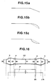
- FIG. 15 is a fragmentary enlarged view illustrating the shape of a tapered end portion of each of fixing rollers of the present embodiment.
- the thickness of the core bar is 1.5 mm.
- FIG. 15a illustrates a fixing roller whose outer diameter is linearly reduced from a largest-diameter portion toward an end portion.
- FIG. 15b illustrates the shape of an outer diameter having a convex circular shape, in which the inclination gradually increases from a portion where taper starts toward an end portion.
- FIG. 15c illustrates the shape of an outer diameter having a concave circlar shape, in which the inclination gradually decreases from a portion where taper starts toward an end portion.
- Table 11 illustrates results of evaluation of corrugation at end portions of the recording material by changing the amount of taper of each of the above-described fixing rollers.
- mark x represents a state in which the number of waves equals at least four
- mark ⁇ represents a state in which the number of waves equals three
- mark ⁇ represents a state in which the number of waves equals two
- mark o represents a state in which the number of waves is equal to or less than one.
- the shape "a" or b is effective.
- the reason why the shapes "a" and b are superior to the shape c can be considered that the pressing roller and the recording material can easily conform to the shape of tapered end portions of the fixing roller, so that the degree of close contact with the fixing roller is improved, and slip, which will cause corrugation at end portions of the recording material, is not produced.
- the inclination of tapered end portions of the fixing roller is constant from a portion where taper starts to the ends of the fixing roller, or that the inclination is small at a portion where taper starts and thereafter gradually increases.
- FIG. 16 is a diagram illustrating the schematic configuration of the shape of the outer diameter of a fixing roller used in a heating fixing device according to the seventh embodiment.
- a fixing roller 93 of the present embodiment is used in a heating fixing device having the same cross-sectional shape as that shown in FIG. 9. Hence, a description of the heating fixing device will be omitted.
- the present embodiment relates to a technique to prevent corrugation at end portions of a recording material for a plurality of sizes of recording materials.
- the fixing roller has an inverse-crown shape in which the outer diameter gradually increases from the center toward end portions. At portions of the fixing roller corresponding to the ends of each size of recording material, the outer diameter of the fixing roller is reduced toward the outside in a tapered shape.
- the fixing roller has an inverse-crown shape in which the outer diameter gradually increases from the center toward end portions
- the above-described effects may also be obtained by using a fixing roller having a straight shape in which the outer diameter is constant from the center toward end portions, forming the above-described tapered shapes corresponding to the respective sizes of recording materials, and adopting an inverse-crown shape for the pressing roller.
- FIG. 17 is a diagram illustrating the shape of the outer diameter of a fixing roller 94 used in a heating fixing device according to an eighth embodiment of the present invention.
- the heating fixing device which uses the fixing roller 94 has the same cross section as that shown in FIG. 9.
- the present embodiment relates to a technique to prevent corrugation at end portions of each recording material for a plurality of sizes of recording materials.
- the present embodiment is applied to wide recording materials, such as the A3 size (297 mm x 420 mm), and the like, and is particularly effective when a releasing layer, made of PFA or the like, is provided on the surface of a pressing roller.
- the present embodiment has a feature in that the inclination of a partial tapered portion of the fixing roller corresponding to each size of recording material increases as the width of the size increases.
- the recording material In the case of using a wide recording material, such as the A3 size, if a nonuniform force is applied in the direction of the width of the recording material, the recording material is apt to be corrugated because the stiffness of the recording material in the direction of the width is weak. Particularly when an entirely black image is recorded, uneven density is apt to be produced in the entirely black image due to the corrugation. This tendency will become more pronounced particularly when a releasing layer, made of PFA or the like, is provided on the surface of the pressing roler, because the recording material slips in the nip region.
- D6 (D7) 30.08 mm within the region where the recording material of the LTR size passes at a position 102 mm from the center.
- the inclinations of respective tapered portions corresponding to respective sizes of recording materials sequentially increase from the center toward end portions of the fixing roller such as 0.02 (the portion corresponding to the B5 size and the EXE size), 0.04 (the portion corresponding to the A4 and the LTR size), 0.085 (the portion corresponding to the B4 size), and 0.115 (the portion corresponding to the A3 size).
- FIG. 18 is a diagram illustrating the shapes of the outer diameters of a fixing roller 95 and a pressing roller 101 used in a heating fixing device according to the ninth embodiment.
- the present embodiment relates to a technique to prevent corrugation at end portions of a recording material for a plurality of sizes of recording materials, and has a feature in that a tapered portion is formed at the fixing roller 95 for the largest size of recording material, and partial tapered portions are formed at the pressing roller 101 for other smaller sizes of recording materials.
- the above-described partial tapered portions are present within the region of the obtained image. Accordingly, a care must be taken so that the shapes of the partial tapered portions do not adversely influence the obtained image.
- a fixing roller comprising a thin core bar having, for example, a thickness equal to or less than 2mm
- the surface temperature of the fixing roller becomes too high at that portion, because thermal conduction of the fixing roller in a lateral direction is inferior.
- uneven density due to excessive fixing will be in some cases produced when, for example, an entire black image is fixed.
- the present embodiment will now be described illustrating a specific example.
- the fixing roller 95 has an inverse-crown shape in which the outer diameter gradually increases from the center toward the ends.
- the outer diameter D1 at the center is 30.0 mm.
- the pressing roller 101 has a straight shape having a constant outer diameter from the center to the ends.
- the outer diameter at the center is 30.0 mm.
- a partial tapered portion is provided from a position 85 mm to a position 95 mm from the center corresponding to the B5 size and the EXE size.
- the outer diameter D6 (D7) at the position of 95 mm is 29.6 mm.
- the thickness of the core bar of the fixing roller 95 is 1.5 mm.
- the present embodiment relates to the shapes of a heater 122 and a heater holder 123 when a thin film 121 is used in a heating fixing device as a heating rotating member.
- the heater 122 and the heater holder 123 are gradually separated from a pressing roller 126 as they reach the ends of the recording material.
- the heating film 121 comprises a fluororesin layer, made of PFA, PFTE or the like, 20 ⁇ m thick coated on a polyimide-film tube 30 ⁇ m thick having an inner diameter of 40 mm.
- the heater 122 having a heating pattern of a heating resistor, made of Ag/Pd or the like, provided on a ceramic substrate, made of alumina or the like, having high heat conductance, which is made by screen printing or the like, is provided on the heater holder 123 made by a heat-resistant resin, such as phenol, a liquid-crystal polymer, PPS or the like.
- the heating film 121 is rotatably driven by a driving roller 124 and a tension roller 125.
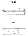
- the pressing roller 126 is in pressure contact with the heating film 121 by a spring (not shown). Since the heat capacity of the heating member is very small according to the above-described configuration, it is possible to provide an energy-saving-type heating fixing device, in which the temperature rises very rapidly, current supply to the heater can be interrupted in a non-operating state, and the current supply can be performed only during a printing operation. In such a heating fixing device, in order to prevent corrugation at end portions of the recording material, as shown in FIG. 20, the heater 122 and the heater holder 123 are separated from the pressing roller 126 from the neighborhood of the positions corresponding to the ends of the recording material.
- the the range of numerical values for the inclination described in the fourth embodiment can be applied to the inclination of the heater 122 separated from the pressing roller 126 without modification. More specifically, in the present embodiment, in order to deal with the LTR size, the heater 122 is separated from the pressing roller 126 with an inclination of 0.04 mm per mm from a position 105 mm from the position corresponding to the center of the image. As a result, the nip formed by the heater 122 and the pressing roller 126 via the heating film 121 has the same shape as that described in the fourth embodiment.
- the width of the nip gradually increases from the center to the position where the heater 122 starts to separate from the pressing roller 126 due to bending of the heater 122 and the pressing roller 126, gradually decreases from the above-described position, and has substantially the same width as that of the center at end portions of the recording material.
- Corrugation at end portions of the recording material is considered to be produced by the following reasons. That is, since the nip width at end portions of the recording material is greater than the nip widths at other portions, a strong stress is applied to the end portions of the recording material.
- FIG. 21 is a diagram illustrating the shape of a heater used in a heating fixing device according to the eleventh embodiment.
- the present embodiment relates to a heating fixing device in which a thin film is used as a heating rotating member. A nip is formed between a pressing roller and a heater 141 via the heating film, and the width of the heater 141 is arranged to be gradually reduced toward end portions of the recording material.
- the heater 141 which is a feature of the present embodiment, includes an alumina sheet, serving as a heater base, whose width is gradually reduced from positions inside the ends of the recording material toward the ends of the heater, and a nip having the above-described desired shape is obtained because of the following reason. That is, in the configuration of the heater 141, heat generated by a heating member 143 can quickly warm the entire heater base 142 because of high heat conductance of alumina, serving as the material for the heater base 142. Hence, the shape of the nip formed between the pressing roller and the heater 141 via the heating film is determined by the shape of the heater base 142 when the region of pressure contact with the pressing roller covers the entire heater.
- the heater base 142 has a width of 5 mm from the center of the recording material to positions inside the ends of the recording material by 4 mm (104 mm from the center in the case of the LTR size). The width is reduced from that positions with an inclination of 0.5 mm per mm.
- a shape, in which the nip width is gradually reduced toward end portions of the recording material can be obtained.
- the same functions and effects as those described in the above-described embodiments can be obtained.
- the above-described functions and effects can be obtained when the inclination, with which the width of the heater base 142 is reduced toward end portions of the recording material, equals at least 0.2 mm per mm.
- the upper limit of the inclination is determined by the limit of permissible fixability at the end portions. According to the investigation, fixability which causes no practical problem was obtained with the values of inclination equal to or less than 1.2 mm per mm. As described above, according to the present embodiment, the above-described functions and effects can be obtained by changing the shape of the nip only by changing the width of the heater, and therefore no force to bend the recording material is exerted. Hence, there is no possibility of adverse influences on the obtained image, and recording materials having small sizes can be easily dealt with.
Landscapes
- Physics & Mathematics (AREA)
- General Physics & Mathematics (AREA)
- Fixing For Electrophotography (AREA)
Applications Claiming Priority (6)
| Application Number | Priority Date | Filing Date | Title |
|---|---|---|---|
| JP10935293 | 1993-05-11 | ||
| JP109352/93 | 1993-05-11 | ||
| JP05109352A JP3119405B2 (ja) | 1993-05-11 | 1993-05-11 | 定着装置及び定着回転体 |
| JP28555293 | 1993-10-21 | ||
| JP285552/93 | 1993-10-21 | ||
| JP28555293A JP3267416B2 (ja) | 1993-10-21 | 1993-10-21 | 加熱定着装置 |
Publications (3)
| Publication Number | Publication Date |
|---|---|
| EP0624830A2 true EP0624830A2 (fr) | 1994-11-17 |
| EP0624830A3 EP0624830A3 (fr) | 1996-02-21 |
| EP0624830B1 EP0624830B1 (fr) | 2001-05-02 |
Family
ID=26449124
Family Applications (1)
| Application Number | Title | Priority Date | Filing Date |
|---|---|---|---|
| EP94830216A Expired - Lifetime EP0624830B1 (fr) | 1993-05-11 | 1994-05-06 | Dispositif de fixage |
Country Status (4)
| Country | Link |
|---|---|
| US (1) | US5450181A (fr) |
| EP (1) | EP0624830B1 (fr) |
| DE (1) | DE69427158T2 (fr) |
| ES (1) | ES2156146T3 (fr) |
Families Citing this family (36)
| Publication number | Priority date | Publication date | Assignee | Title |
|---|---|---|---|---|
| US5932125A (en) * | 1995-11-16 | 1999-08-03 | Fuji Electric Co., Ltd. | Roller for fixing toner and method for manufacturing same |
| US5655201A (en) * | 1995-12-21 | 1997-08-05 | Xerox Corporation | Tapered rollers for migration imaging system |
| US5820446A (en) * | 1996-06-07 | 1998-10-13 | Komag, Incorporated | Apparatus and method for texturing rigid-disk substrates |
| US5926680A (en) * | 1996-07-16 | 1999-07-20 | Asahi Kogaku Kogyo Kabushiki Kaisha | Fixing unit |
| JPH1124462A (ja) * | 1997-05-09 | 1999-01-29 | Hitachi Koki Co Ltd | トナー像加熱装置 |
| JP3854690B2 (ja) * | 1997-08-04 | 2006-12-06 | キヤノン株式会社 | 画像形成装置 |
| JPH11133803A (ja) | 1997-10-30 | 1999-05-21 | Canon Inc | 定着装置及び画像形成装置 |
| JP2000122441A (ja) * | 1998-10-21 | 2000-04-28 | Fuji Xerox Co Ltd | 画像形成装置、転写定着装置、および画像形成方法 |
| JP2001183935A (ja) * | 1999-12-27 | 2001-07-06 | Nitto Kogyo Co Ltd | 定着用ローラ |
| US6229982B1 (en) * | 2000-04-27 | 2001-05-08 | Toshiba Tec Kabushiki Kaisha | Fixing apparatus, fixing method and image forming apparatus |
| JP2002082559A (ja) * | 2000-06-22 | 2002-03-22 | Ricoh Co Ltd | 加熱ローラ及び加熱ローラの製造方法及び加熱装置及び定着装置及び画像形成装置 |
| US6266510B1 (en) | 2000-09-18 | 2001-07-24 | Lexmark International, Inc. | Control of wrinkling in belt fuser by nip configuration |
| JP3814542B2 (ja) | 2001-02-20 | 2006-08-30 | キヤノン株式会社 | 像加熱装置 |
| US20040154146A1 (en) * | 2001-05-17 | 2004-08-12 | Pruitt Paul R. | Web spreader roll and methods for spreading webs of material |
| JP4933002B2 (ja) | 2001-07-26 | 2012-05-16 | キヤノン株式会社 | 加熱定着装置および加熱用金属製スリーブ |
| JP3970122B2 (ja) | 2001-08-10 | 2007-09-05 | キヤノン株式会社 | ヒータに接触する金属製回転体を有する像加熱装置及びこの回転体及びこの回転体の製造方法 |
| JP4261859B2 (ja) | 2001-10-09 | 2009-04-30 | キヤノン株式会社 | 像加熱装置 |
| JP3817482B2 (ja) * | 2002-02-01 | 2006-09-06 | キヤノン株式会社 | 加熱装置および画像形成装置 |
| JP4054599B2 (ja) * | 2002-04-25 | 2008-02-27 | キヤノン株式会社 | 像加熱装置 |
| JP2004170950A (ja) * | 2002-11-06 | 2004-06-17 | Canon Inc | 像加熱装置 |
| JP4095406B2 (ja) * | 2002-11-06 | 2008-06-04 | キヤノン株式会社 | 加熱定着装置 |
| US20040192528A1 (en) * | 2003-03-31 | 2004-09-30 | Munehiko Fukase | Ceramic roller |
| JP4053010B2 (ja) * | 2004-02-24 | 2008-02-27 | 株式会社沖データ | 現像装置と現像装置を内蔵する画像形成装置 |
| JP4262119B2 (ja) * | 2004-02-27 | 2009-05-13 | キヤノン株式会社 | 画像形成装置 |
| JP2005316443A (ja) * | 2004-03-30 | 2005-11-10 | Canon Inc | 像加熱装置及びこの装置に用いられる搬送ローラ |
| KR100561428B1 (ko) * | 2004-05-25 | 2006-03-17 | 삼성전자주식회사 | 배지장치 및 이를 적용한 화상형성장치 |
| US7155156B2 (en) * | 2005-03-14 | 2006-12-26 | Kabushiki Kaisha Toshiba | Fixing apparatus |
| JP4455548B2 (ja) * | 2005-07-26 | 2010-04-21 | キヤノン株式会社 | 像加熱装置 |
| JP5488879B2 (ja) * | 2009-01-14 | 2014-05-14 | 株式会社リコー | 定着装置及び画像形成装置 |
| US8364051B2 (en) * | 2009-03-17 | 2013-01-29 | Ricoh Company, Ltd. | Fixing device and image forming apparatus including same |
| US8391766B2 (en) * | 2009-09-01 | 2013-03-05 | Ricoh Company, Ltd. | Fixing device and image forming apparatus incorporating same |
| JP2012027325A (ja) * | 2010-07-26 | 2012-02-09 | Ricoh Co Ltd | 定着装置及び画像形成装置 |
| DE102010049068A1 (de) * | 2010-10-20 | 2012-04-26 | Mtu Aero Engines Gmbh | Vorrichtung zum Herstellen, Reparieren und/oder Austauschen eines Bauteils mittels eines durch Energiestrahlung verfestigbaren Pulvers, sowie ein Verfahren und ein gemäß dem Verfahren hergestelltes Bauteil |
| US8886098B2 (en) | 2011-03-14 | 2014-11-11 | Xerox Corporation | Apparatus and method to control media wrinkling through roll flaring |
| JP5762220B2 (ja) * | 2011-08-31 | 2015-08-12 | 富士フイルム株式会社 | 搬送装置および画像形成装置 |
| JP5911780B2 (ja) * | 2012-09-24 | 2016-04-27 | コニカミノルタ株式会社 | 定着装置および画像形成装置 |
Family Cites Families (17)
| Publication number | Priority date | Publication date | Assignee | Title |
|---|---|---|---|---|
| US3884623A (en) * | 1973-02-16 | 1975-05-20 | Dyk Research Corp Van | Xerographic fuser roller |
| US4008955A (en) * | 1975-05-12 | 1977-02-22 | Xerox Corporation | Fuser assembly for an electrophotograhic copying machine |
| JPS58194527A (ja) * | 1982-05-10 | 1983-11-12 | Showa Electric Wire & Cable Co Ltd | ヒ−トロ−ルの製造方法 |
| DE3323068A1 (de) * | 1983-06-27 | 1985-01-03 | Hoechst Ag, 6230 Frankfurt | Walzenfixiervorrichtung mit einem walzenpaar |
| JPS60100164A (ja) * | 1983-11-07 | 1985-06-04 | Fuji Xerox Co Ltd | 定着装置 |
| JPS60128472A (ja) * | 1983-12-15 | 1985-07-09 | Konishiroku Photo Ind Co Ltd | 熱ロ−ラ定着装置 |
| JPS60260076A (ja) * | 1984-06-06 | 1985-12-23 | Konishiroku Photo Ind Co Ltd | 定着装置 |
| JPS61151676A (ja) * | 1984-12-26 | 1986-07-10 | Junkosha Co Ltd | ロ−ラ定着装置 |
| JPS61184574A (ja) * | 1985-02-12 | 1986-08-18 | Konishiroku Photo Ind Co Ltd | 定着装置 |
| US4804576A (en) * | 1985-02-28 | 1989-02-14 | Canon Kabushiki Kaisha | Elastic rotatable member |
| JPS61251879A (ja) * | 1985-04-30 | 1986-11-08 | Katsuragawa Denki Kk | 定着装置 |
| JP2509544B2 (ja) * | 1987-08-07 | 1996-06-19 | キヤノン株式会社 | 弾性回転体及びそれを有する定着装置 |
| DE3887669T2 (de) * | 1987-12-04 | 1994-06-23 | Canon Kk | Rotierendes Bauteil für Fixiergerät und Fixiergerät hierfür. |
| JP2796307B2 (ja) * | 1988-06-24 | 1998-09-10 | 株式会社金陽社 | 定着器用ロール |
| JPH07104636B2 (ja) * | 1989-04-03 | 1995-11-13 | キヤノン株式会社 | 定着装置 |
| US5001401A (en) * | 1989-04-10 | 1991-03-19 | Valmont Industries, Inc. | Dual voltage ballast |
| US5264902A (en) * | 1990-02-07 | 1993-11-23 | Canon Kabushiki Kaisha | Image forming device |
-
1994
- 1994-04-21 US US08/230,906 patent/US5450181A/en not_active Expired - Lifetime
- 1994-05-06 EP EP94830216A patent/EP0624830B1/fr not_active Expired - Lifetime
- 1994-05-06 ES ES94830216T patent/ES2156146T3/es not_active Expired - Lifetime
- 1994-05-06 DE DE69427158T patent/DE69427158T2/de not_active Expired - Lifetime
Also Published As
| Publication number | Publication date |
|---|---|
| EP0624830B1 (fr) | 2001-05-02 |
| DE69427158T2 (de) | 2001-10-25 |
| ES2156146T3 (es) | 2001-06-16 |
| US5450181A (en) | 1995-09-12 |
| EP0624830A3 (fr) | 1996-02-21 |
| DE69427158D1 (de) | 2001-06-07 |
Similar Documents
| Publication | Publication Date | Title |
|---|---|---|
| US5450181A (en) | Fixing device | |
| US5778294A (en) | Electrophotographic apparatus and belt fixing device with non-uniform nip pressure | |
| JP5446063B2 (ja) | 定着装置及び画像形成装置 | |
| EP0373651A2 (fr) | Feuille à nettoyer pour membre de fixage rotatif et appareil de formation d'images avec membre de fixage rotatif | |
| JP3882821B2 (ja) | 画像形成装置 | |
| EP1925989A2 (fr) | Appareil de formation d'images contenant une courroie de fixation et un rouleau de pression | |
| US7107681B2 (en) | Heating roller, method of producing the heating roller, and heating device, fixing device and image forming apparatus using the heating roller | |
| US8953996B2 (en) | Fixing apparatus for fixing toner onto a sheet | |
| US6687482B2 (en) | Heating apparatus and image forming apparatus incorporating the same | |
| CN102981388B (zh) | 成像设备 | |
| JPH10142971A (ja) | 画像形成装置 | |
| EP1580621B1 (fr) | Appareil de fixage et de formation d'images | |
| US8068765B2 (en) | Fixing device and image forming apparatus including the same | |
| EP1098229B1 (fr) | Appareil de fixage utilisant de la faible pression de contact | |
| US9025982B2 (en) | Image heating apparatus and image forming apparatus having plurality of image forming or conveying modes corresponding to the grain direction of a sheet | |
| JP3267416B2 (ja) | 加熱定着装置 | |
| JP4770944B2 (ja) | 定着装置および画像形成装置 | |
| JP6053660B2 (ja) | 定着装置、画像形成装置 | |
| JP3119405B2 (ja) | 定着装置及び定着回転体 | |
| JP2023180304A (ja) | 定着装置 | |
| JP2004279857A (ja) | 加熱定着装置および画像形成装置 | |
| JPH07121045A (ja) | 加熱定着装置 | |
| JP2004234951A (ja) | 加熱装置 | |
| JP4087677B2 (ja) | ベルト装置及び印刷機 | |
| JP2000056601A (ja) | 画像形成装置の定着装置 |
Legal Events
| Date | Code | Title | Description |
|---|---|---|---|
| PUAI | Public reference made under article 153(3) epc to a published international application that has entered the european phase |
Free format text: ORIGINAL CODE: 0009012 |
|
| AK | Designated contracting states |
Kind code of ref document: A2 Designated state(s): DE ES FR GB IT NL |
|
| PUAL | Search report despatched |
Free format text: ORIGINAL CODE: 0009013 |
|
| AK | Designated contracting states |
Kind code of ref document: A3 Designated state(s): DE ES FR GB IT NL |
|
| 17P | Request for examination filed |
Effective date: 19960705 |
|
| 17Q | First examination report despatched |
Effective date: 19960820 |
|
| GRAG | Despatch of communication of intention to grant |
Free format text: ORIGINAL CODE: EPIDOS AGRA |
|
| GRAG | Despatch of communication of intention to grant |
Free format text: ORIGINAL CODE: EPIDOS AGRA |
|
| GRAH | Despatch of communication of intention to grant a patent |
Free format text: ORIGINAL CODE: EPIDOS IGRA |
|
| GRAG | Despatch of communication of intention to grant |
Free format text: ORIGINAL CODE: EPIDOS AGRA |
|
| GRAG | Despatch of communication of intention to grant |
Free format text: ORIGINAL CODE: EPIDOS AGRA |
|
| GRAH | Despatch of communication of intention to grant a patent |
Free format text: ORIGINAL CODE: EPIDOS IGRA |
|
| GRAA | (expected) grant |
Free format text: ORIGINAL CODE: 0009210 |
|
| AK | Designated contracting states |
Kind code of ref document: B1 Designated state(s): DE ES FR GB IT NL |
|
| REF | Corresponds to: |
Ref document number: 69427158 Country of ref document: DE Date of ref document: 20010607 |
|
| ET | Fr: translation filed | ||
| REG | Reference to a national code |
Ref country code: ES Ref legal event code: FG2A Ref document number: 2156146 Country of ref document: ES Kind code of ref document: T3 |
|
| ITF | It: translation for a ep patent filed | ||
| REG | Reference to a national code |
Ref country code: GB Ref legal event code: IF02 |
|
| PLBE | No opposition filed within time limit |
Free format text: ORIGINAL CODE: 0009261 |
|
| STAA | Information on the status of an ep patent application or granted ep patent |
Free format text: STATUS: NO OPPOSITION FILED WITHIN TIME LIMIT |
|
| 26N | No opposition filed | ||
| PGFP | Annual fee paid to national office [announced via postgrant information from national office to epo] |
Ref country code: NL Payment date: 20090527 Year of fee payment: 16 Ref country code: ES Payment date: 20090407 Year of fee payment: 16 |
|
| PGFP | Annual fee paid to national office [announced via postgrant information from national office to epo] |
Ref country code: IT Payment date: 20090515 Year of fee payment: 16 Ref country code: FR Payment date: 20090520 Year of fee payment: 16 |
|
| REG | Reference to a national code |
Ref country code: NL Ref legal event code: V1 Effective date: 20101201 |
|
| REG | Reference to a national code |
Ref country code: FR Ref legal event code: ST Effective date: 20110131 |
|
| PG25 | Lapsed in a contracting state [announced via postgrant information from national office to epo] |
Ref country code: NL Free format text: LAPSE BECAUSE OF NON-PAYMENT OF DUE FEES Effective date: 20101201 Ref country code: IT Free format text: LAPSE BECAUSE OF NON-PAYMENT OF DUE FEES Effective date: 20100506 |
|
| PG25 | Lapsed in a contracting state [announced via postgrant information from national office to epo] |
Ref country code: FR Free format text: LAPSE BECAUSE OF NON-PAYMENT OF DUE FEES Effective date: 20100531 |
|
| REG | Reference to a national code |
Ref country code: ES Ref legal event code: FD2A Effective date: 20110715 |
|
| PG25 | Lapsed in a contracting state [announced via postgrant information from national office to epo] |
Ref country code: ES Free format text: LAPSE BECAUSE OF NON-PAYMENT OF DUE FEES Effective date: 20110705 |
|
| PG25 | Lapsed in a contracting state [announced via postgrant information from national office to epo] |
Ref country code: ES Free format text: LAPSE BECAUSE OF NON-PAYMENT OF DUE FEES Effective date: 20100507 |
|
| PGFP | Annual fee paid to national office [announced via postgrant information from national office to epo] |
Ref country code: DE Payment date: 20120531 Year of fee payment: 19 |
|
| PGFP | Annual fee paid to national office [announced via postgrant information from national office to epo] |
Ref country code: GB Payment date: 20120517 Year of fee payment: 19 |
|
| GBPC | Gb: european patent ceased through non-payment of renewal fee |
Effective date: 20130506 |
|
| PG25 | Lapsed in a contracting state [announced via postgrant information from national office to epo] |
Ref country code: DE Free format text: LAPSE BECAUSE OF NON-PAYMENT OF DUE FEES Effective date: 20131203 |
|
| REG | Reference to a national code |
Ref country code: DE Ref legal event code: R119 Ref document number: 69427158 Country of ref document: DE Effective date: 20131203 |
|
| PG25 | Lapsed in a contracting state [announced via postgrant information from national office to epo] |
Ref country code: GB Free format text: LAPSE BECAUSE OF NON-PAYMENT OF DUE FEES Effective date: 20130506 |