EP0625021B1 - Procede de rejet des interferences electriques provenant d'appareils de mesures physiologiques - Google Patents
Procede de rejet des interferences electriques provenant d'appareils de mesures physiologiques Download PDFInfo
- Publication number
- EP0625021B1 EP0625021B1 EP93904906A EP93904906A EP0625021B1 EP 0625021 B1 EP0625021 B1 EP 0625021B1 EP 93904906 A EP93904906 A EP 93904906A EP 93904906 A EP93904906 A EP 93904906A EP 0625021 B1 EP0625021 B1 EP 0625021B1
- Authority
- EP
- European Patent Office
- Prior art keywords
- current
- waveform
- voltage
- determining
- power
- Prior art date
- Legal status (The legal status is an assumption and is not a legal conclusion. Google has not performed a legal analysis and makes no representation as to the accuracy of the status listed.)
- Expired - Lifetime
Links
Images

Classifications
-
- A—HUMAN NECESSITIES
- A61—MEDICAL OR VETERINARY SCIENCE; HYGIENE
- A61B—DIAGNOSIS; SURGERY; IDENTIFICATION
- A61B5/00—Measuring for diagnostic purposes; Identification of persons
- A61B5/24—Detecting, measuring or recording bioelectric or biomagnetic signals of the body or parts thereof
- A61B5/30—Input circuits therefor
- A61B5/301—Input circuits therefor providing electrical separation, e.g. by using isolating transformers or optocouplers
-
- A—HUMAN NECESSITIES
- A61—MEDICAL OR VETERINARY SCIENCE; HYGIENE
- A61B—DIAGNOSIS; SURGERY; IDENTIFICATION
- A61B5/00—Measuring for diagnostic purposes; Identification of persons
- A61B5/02—Detecting, measuring or recording for evaluating the cardiovascular system, e.g. pulse, heart rate, blood pressure or blood flow
- A61B5/026—Measuring blood flow
- A61B5/0275—Measuring blood flow using tracers, e.g. dye dilution
- A61B5/028—Measuring blood flow using tracers, e.g. dye dilution by thermo-dilution
-
- A—HUMAN NECESSITIES
- A61—MEDICAL OR VETERINARY SCIENCE; HYGIENE
- A61B—DIAGNOSIS; SURGERY; IDENTIFICATION
- A61B5/00—Measuring for diagnostic purposes; Identification of persons
- A61B5/24—Detecting, measuring or recording bioelectric or biomagnetic signals of the body or parts thereof
- A61B5/30—Input circuits therefor
- A61B5/307—Input circuits therefor specially adapted for particular uses
- A61B5/308—Input circuits therefor specially adapted for particular uses for electrocardiography [ECG]
Definitions
- the present invention generally relates to the field of electronic noise rejection, and more particularly, relates to methods and apparatus for minimizing the effects of electromagnetic interference on physiological measurements.
- Electronic monitors are currently used to measure various physiological parameters (e.g., blood pressure, heart rate, EKG, temperature) of patients during surgical procedures in the operating room (OR) and during care in intensive care units (ICUs).
- physiological parameters e.g., blood pressure, heart rate, EKG, temperature
- ICUs intensive care units
- other electronic equipment in use in the OR or ICU e.g., electrocautery or electrosurgical devices
- electrocautery or electrosurgical devices can generate electrical interference which corrupts the measured signals and invalidates the displayed numeric readings and waveforms.
- Present monitors incorporate various means for minimizing this interference in EKG and blood pressure waveforms, but systems used to measure temperature and cardiac output remain susceptible to this type of interference.
- a known method for performing cardiac output (CO) measurements employs heat and pulmonary artery catheters and relies upon the continuous measurement of pulmonary artery temperature and heater power to accurately compute cardiac output.
- CO cardiac output
- EP-0 126 931 describes an apparatus for measuring flow through a fluid system in which a heating element driven by a stochastic generator introduces heat into the system which is detected by a thermistor and high gain amplifier. There is no teaching of electrical isolation of any components in order to minimize electrosurgical interference.
- a primary object of the present invention is to provide methods and apparatus for minimizing the effects of electromagnetic or electrical interference on heat-based cardiac output measurements.
- a further object of the invention is to provide methods that are generally applicable to physiological signals that can be transferred across an isolation transformer.
- the present invention includes the steps of or means for: (a) injecting an indicator into a system for which a parameter of interest is to be measured, (b) measuring a first signal that is both indicative of the amount of the indicator injected in step (a) and substantially free of the effects of any electromagnetic interference, (c) determining on the basis of the first signal a first waveform representative of the amount of indicator delivered into the system as a function of time, where the first waveform is substantially free of the effects of the electromagnetic interference, (d) measuring a second signal that is indicative of a response of the system to the indicator, (e) determining on the basis of the second signal a second waveform representative of the response as a function of time, and (f) determining a system transfer function by cross-correlating the first waveform with the second waveform.
- the system transfer function will be both substantially uncorrupted by electromagnetic interference and indicative of the parameter of interest.
- the system is a patient, the parameter of interest is a physiological parameter, and step (a) comprises supplying power to a catheter-mounted heating element associated with the patient via an isolation transformer and a carrier frequency; step (b) comprises measuring a voltage and a current on a primary side of the isolation transformer; and step (c) comprises determining a voltage and current on a secondary side of the isolation transformer on the basis of the measured primary-side voltage and current, which step may include translating the primary-side voltage and current into a corresponding secondary-side voltage and current by using a model characterizing properties of the isolation transformer.
- step (c) may comprise calculating the power delivered to and resistance of the catheter-mounted heater on the basis of the secondary voltage and current; and the first waveform may be representative of the power delivered to the catheter-mounted heater.
- the second signal may be indicative of the temperature of the patient's blood; the second waveform may be representative of the blood temperature as a function of time; and step (f) may comprise cross-correlating the heater power waveform with the blood temperature waveform.
- Especially preferred embodiments of the present invention provide methods for substantially eliminating the effects of electrosurgical interference on continuous, heat-based cardiac output measurements. Such methods employ several procedures, including:
- Calibration of the transformer model can be achieved for a specific instrument by manually or electronically switching a known load resistance in place of the catheter circuit and performing a series of measurements.
- a calibration procedure in accordance with the present invention is described below in connection with the detailed description of preferred embodiments.
- the uncorrupted voltage and current measurements derived with the transformer and transformer model may be used to provide a reliable measure of heater resistance, which may in turn be used to determine whether the heater is properly functioning.
- FIGURES 1-4 A preferred embodiment of the present invention will now be described with respect to FIGURES 1-4 for use in a continuous cardiac output (CCO) monitor.
- CCO continuous cardiac output
- the CCO monitor provides continuous cardiac output measurements using thermodilution-based techniques in conjunction with a pulmonary artery catheter.
- the catheter has a heating element of the type described, for example, by Yelderman et al. in U.S. Patent Application Serial No. 07/647,578, filed January 29, 1991, which is adapted to be placed in the region of the right atrium/ventricle of a patient.
- the heating element is powered by a pulsed (ON-OFF) signal and therefore sends a pulsed heat signal into the patient's blood.
- a thermistor near the catheter tip in the pulmonary artery senses the resultant blood temperature and these two signals are processed to provide CCO. See, e.g. , Mark L. Yelderman, "Continuous Measurement of Cardiac Output With the Use of Stochastic System Identification Techniques", J Clin Monit 1990; 6(4):322-332.
- the power delivered to the heating element must be accurately measured since this is indicative of the amount of indicator (heat) which is delivered into the blood. It is also necessary to accurately measure the resistance of the heating element, since this is used to estimate both the core and the surface temperatures of the heating element. These measurements are required for heater element monitoring and control algorithms. See Mark L. Yelderman, et al., "Thermal Safety of a Filamented Pulmonary Artery Catheter", J Clin Monit , (In Press 1992).
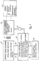
- FIGURE 1 is a block diagram of a system for delivering a heart indicator in accordance with the present invention.
- the system of FIGURE 1 is embodied in the above-mentioned CCO monitor.
- a primary-side electronics block 10 includes a 100 KHz power amplifier and current and voltage meters.
- the primary-side electronics block 10 is coupled to the primary side of an isolation transformer 12.
- the secondary side of the isolation transformer 12 is coupled to the secondary-side electronics block 14, which includes a calibration resistor and a relay.
- the secondary-side electronics block 14 is coupled to a catheter-mounted heater element that is adapted to be attached to a patient whose cardiac output is to be measured.
- the catheter-mounted heater element and patient are represented by block 16 in FIGURE 1.
- the primary-side electronics block 10 is further coupled to a digital controller block 18, which includes means (e.g., software) for calibration of the primary current and voltage meters (contained in the primary-side electronics block 10) and for conversion of primary-side measurements to heater element resistance and power measurements.
- the digital controller block 18 passes digital control data via a bus 26 to the primary-side electronics block 10, and receives current and voltage data, via another bus 24, from the primary-side electronics block.
- Digital controller block 18 is further coupled to a block 20 containing heater element monitoring and control functions.
- Block 20 provides digital control data to the digital controller block 18 via bus 32, and receives heater element power and resistance data via bus 30 from the digital controller block 18.
- the digital controller block 18 provides control signals, via relay control bus 28 and opto-isolator 22, to the secondary-side electronics block 14.
- an isolation transformer is employed to couple the power amplifier circuitry, which outputs a 100 KHz signal, to the heater element.
- the current and voltage measurement circuitry is placed on the primary side of the transformer to keep the circuitry to a minimum on the isolated secondary side.
- the heater element since the heater element is on the secondary side, it is necessary to relate the primary currents/voltages to the secondary currents/voltages.
- FIGURE 2 is a model of a non-ideal transformer.
- the circuit components are:
- the analysis here is simplified because: (1) the signal is a 100 KHz sinewave, and (2) the current and voltage for this circuit and this frequency have a negligible phase lag. This allows the RMS equivalent DC circuit of FIGURE 3 to be used.
- the primary current and voltage measurement hardware/software is calibrated in terms of the secondary current and voltage values; for this purpose the simple resistor network of FIGURE 4 (which "images" the primary circuit onto the secondary in accordance with the transformer turns ratio) may be analyzed.
- Im Vs/(N 2 *Rpc) + Is[1 + Rx/(N 2 *Rpc)] where:
- the CCO monitor includes a relay on the output of the isolation transformer that can switch between the external catheter cable/heating element and an internal calibration resistor, R_cal.
- the hardware calibration of the monitor includes a reference level adjustment on the 100 KHz power signal.
- the runtime software-controlled calibration procedure is as follows:
- R_loss the RMS equivalent resistance of the heater element
- R_loss the series resistance from the secondary terminals of the transformer to the heater element.
- R_loss is a function of catheter/heater element design, it may be programmed into a catheter EEPROM of the type described by Yelderman et al. in U.S. Patent Application Serial No. 07/769,536, filed October 1, 1991.
- R_loss is 2.25 ohms and R_he ranges from 35 to 45 ohms.
- R_he and P_he are input to the heater element monitoring and control algorithms.
- P_he is also input to a CCO estimation algorithm as described in the above-cited U.S. Patent Application Serial No. 07/510,897.
- the CCO monitor includes a resistance adjustment resistor (R_adj) placed in parallel with the catheter's heater element.
- the R_adj resistance includes a ten-turn 100K ⁇ potentiometer in series with a 10K ⁇ fixed resistor (to protect against 0 ohms on the ten-turn potentiometer).
- R_adj has been safely ignored in the above discussions due to the fact that: R_loss + R_he ⁇ 45 ohs ⁇ R_adj (approx. 60 K ⁇ ). Including R_adj gives rise to negligible terms in the network equations.
- the monitor undergoes the following resistance calibration procedure:
- the present invention is not limited to applications in systems for measuring cardiac output, since it is apparent that the invention may be advantageously applied in other kinds of electronic systems that suffer from electromagnetic noise.
- approaches other than use of an isolation transformer may be used to produce one uncorrupted signal for use in a cross-correlation operation with a second corrupted signal.
- a software routine may be applied to the corrupted temperature data to generate an uncorrupted waveform which may then be used together with a second waveform (e.g. , a corrupted heater power waveform) to produce an uncorrupted system transfer function which can be used to measure cardiac output.
- a second waveform e.g. , a corrupted heater power waveform
Landscapes
- Health & Medical Sciences (AREA)
- Life Sciences & Earth Sciences (AREA)
- Engineering & Computer Science (AREA)
- Molecular Biology (AREA)
- Animal Behavior & Ethology (AREA)
- Pathology (AREA)
- Physics & Mathematics (AREA)
- Biomedical Technology (AREA)
- Heart & Thoracic Surgery (AREA)
- Medical Informatics (AREA)
- Veterinary Medicine (AREA)
- Surgery (AREA)
- Biophysics (AREA)
- General Health & Medical Sciences (AREA)
- Public Health (AREA)
- Cardiology (AREA)
- Hematology (AREA)
- Physiology (AREA)
- Power Engineering (AREA)
- Surgical Instruments (AREA)
- Measuring Pulse, Heart Rate, Blood Pressure Or Blood Flow (AREA)
- Measurement And Recording Of Electrical Phenomena And Electrical Characteristics Of The Living Body (AREA)
Claims (5)
- Procédé destiné à éliminer sensiblement les effets des interférences électrochirurgicales sur des mesures en continu de débit cardiaque basées sur la chaleur (CO), comprenant les étapes de:(a) fourniture de puissance, par l'intermédiaire d'un transformateur d'isolation (12) et d'une fréquence porteuse, à un élément de chauffage monté sur cathéter (16) associé avec un patient dont la mesure de CO doit être obtenue;(b) mesure d'une tension (Vm) et d'un courant (Im) sur un côté primaire du transformateur d'isolation;(c) détermination d'une tension (Vs) et d'un courant (Is) sur un côté secondaire dudit transformateur en fonction de la tension et du courant mesurés du côté primaire;(d) détermination de la puissance (P_he) délivrée audit élément de chauffage monté sur cathéter et de sa résistance (R_he) en fonction de la tension et du courant du côté secondaire;(e) détermination d'une forme d'onde de puissance d'élément de chauffage en fonction de la puissance délivrée audit élément de chauffage monté sur cathéter et de sa résistance, ladite forme d'onde de puissance d'élément de chauffage étant sensiblement exempte d'interférences électriques dues aux dispositifs électrochirurgicaux;(f) mesure d'un signal qui est représentatif d'une réponse à l'entrée de chaleur dans le patient en conséquence de la puissance délivrée à l'élément de chauffage monté sur cathéter;(g) détermination, en fonction dudit signal, d'une seconde forme d'onde représentative de ladite réponse en fonction du temps; et(h) détermination d'une fonction de transfert de système par corrélation croisée entre ladite forme d'onde de puissance d'élément de chauffage et ladite seconde forme d'onde, ladite fonction de transfert de système étant à la fois sensiblement inaltérée par lesdites interférences électromagnétiques et représentative de ladite mesure de débit cardiaque.
- Procédé selon la revendication 1 dans lequel le signal mesuré est représentatif de la température du sang dudit patient et ladite seconde forme d'onde est représentative de ladite température du sang en fonction du temps.
- Instrument destiné à réaliser des mesures en continu de débit cardiaque basées sur la chaleur (CO) sur un patient tout en éliminant sensiblement les effets des interférences électrochirurgicales sur celles-ci, comprenant:(a) un moyen (10) destiné à fournir de la puissance, par l'intermédiaire d'un transformateur d'isolation (12) et d'une fréquence porteuse, à un élément de chauffage monté sur cathéter (16) associé avec un patient dont la mesure de CO doit être obtenue;(b) un moyen (10) destiné à mesurer une tension (Vm) et un courant (Im) sur un côté primaire du transformateur d'isolation;(c) un moyen (18) destiné à déterminer une tension (Vs) et un courant (Is) sur un côté secondaire dudit transformateur en fonction de la tension et du courant mesurés du côté primaire;(d) un moyen (18) destiné à déterminer la puissance (P_he) délivrée audit élément de chauffage monté sur cathéter et sa résistance (R_he) en fonction de la tension et du courant du côté secondaire;(e) un moyen (18) destiné à déterminer une forme d'onde de puissance d'élément de chauffage en fonction de ladite puissance délivrée audit élément de chauffage monté sur cathéter et de sa résistance, ladite forme d'onde de puissance d'élément de chauffage étant sensiblement exempte d'interférences électriques dues aux dispositifs électrochirurgicaux;(f) un moyen (14) destiné à mesurer un signal qui est représentatif d'une réponse à l'entrée de chaleur dans le patient en conséquence de la puissance délivrée à l'élément de chauffage monté sur cathéter;(g) un moyen (18) destiné à déterminer, en fonction dudit signal, une seconde forme d'onde représentative de ladite réponse en fonction du temps; et(h) un moyen (18) destiné à déterminer une fonction de transfert de système par corrélation croisée entre ladite forme d'onde de puissance d'élément de chauffage et ladite seconde forme d'onde, ladite fonction de transfert de système étant à la fois sensiblement inaltérée par lesdites interférences électromagnétiques et représentative de ladite mesure de débit cardiaque.
- Instrument selon la revendication 3, dans lequel le signal mesuré est représentatif de la température de sang dudit patient et ladite seconde forme d'onde est représentative de ladite température de sang en fonction du temps.
- Instrument selon la revendication 3, dans lequel ledit moyen (18) destiné à déterminer une tension (Vs) et un courant (Is) du côté secondaire dudit transformateur comporte un modèle caractérisant les propriétés du transformateur d'isolation.
Applications Claiming Priority (3)
| Application Number | Priority Date | Filing Date | Title |
|---|---|---|---|
| US07/832,410 US5305760A (en) | 1992-02-07 | 1992-02-07 | Method for rejecting electrical interference from physiological measurements |
| US832410 | 1992-02-07 | ||
| PCT/US1993/001015 WO1993015655A1 (fr) | 1992-02-07 | 1993-01-28 | Procede de rejet des interferences electriques provenant d'appareils de mesures physiologiques |
Publications (2)
| Publication Number | Publication Date |
|---|---|
| EP0625021A1 EP0625021A1 (fr) | 1994-11-23 |
| EP0625021B1 true EP0625021B1 (fr) | 1998-03-18 |
Family
ID=25261557
Family Applications (1)
| Application Number | Title | Priority Date | Filing Date |
|---|---|---|---|
| EP93904906A Expired - Lifetime EP0625021B1 (fr) | 1992-02-07 | 1993-01-28 | Procede de rejet des interferences electriques provenant d'appareils de mesures physiologiques |
Country Status (6)
| Country | Link |
|---|---|
| US (1) | US5305760A (fr) |
| EP (1) | EP0625021B1 (fr) |
| JP (1) | JP3303035B2 (fr) |
| CA (1) | CA2129553C (fr) |
| DE (1) | DE69317549T2 (fr) |
| WO (1) | WO1993015655A1 (fr) |
Families Citing this family (92)
| Publication number | Priority date | Publication date | Assignee | Title |
|---|---|---|---|---|
| US5797398A (en) | 1993-08-13 | 1998-08-25 | Thermal Technologies, Inc. | Method and apparatus for measuring continuous blood flow at low power |
| US5636638A (en) * | 1994-06-29 | 1997-06-10 | Baxter International Inc. | Electrical power amplifier for continuous cardiac output monitoring |
| US5886576A (en) * | 1996-10-16 | 1999-03-23 | Baxter International Inc. | Electrical power amplifier for continuous cardiac output monitoring |
| US5991700A (en) * | 1997-10-15 | 1999-11-23 | Sherwood Services, A.G. | EMI stability indicator for tympanic thermometer |
| US6285909B1 (en) | 1999-05-27 | 2001-09-04 | Cardiac Pacemakers, Inc. | Preserving patient specific data in implantable pulse generator systems |
| FI108702B (fi) * | 1999-09-29 | 2002-03-15 | Instrumentarium Oyj | Järjestelmä ja menetelmä sydämen lyöntitilavuuden mittaamiseksi |
| US6620157B1 (en) | 2000-12-28 | 2003-09-16 | Senorx, Inc. | High frequency power source |
| US8133218B2 (en) | 2000-12-28 | 2012-03-13 | Senorx, Inc. | Electrosurgical medical system and method |
| US20050004559A1 (en) | 2003-06-03 | 2005-01-06 | Senorx, Inc. | Universal medical device control console |
| FI110990B (fi) | 2001-01-29 | 2003-05-15 | Instrumentarium Oyj | Katetrin lämmityspiiri jatkuvaan sydämen minuuttitilavuuden mittaamiseen |
| US6433524B1 (en) | 2001-03-15 | 2002-08-13 | Rosemount Aerospace Inc. | Resistive bridge interface circuit |
| US6730884B2 (en) * | 2001-11-05 | 2004-05-04 | Liebert Corporation | Protective circuit for electrical heating element |
| US7291123B2 (en) * | 2003-06-04 | 2007-11-06 | Gambro Lundia | Joint for fluid transport lines for medical use |
| US7632235B1 (en) * | 2004-11-22 | 2009-12-15 | Pacesetter, Inc. | System and method for measuring cardiac output via thermal dilution using an implantable medical device with an external ultrasound power delivery system |
| US8795195B2 (en) | 2004-11-29 | 2014-08-05 | Senorx, Inc. | Graphical user interface for tissue biopsy system |
| CA2662789C (fr) | 2006-06-05 | 2019-07-02 | Senorx, Inc. | Systeme de biopsie a imagerie ultrasonore integree |
| US8396806B2 (en) | 2007-10-30 | 2013-03-12 | Red Hat, Inc. | End user license agreements associated with messages |
| WO2016086084A1 (fr) | 2014-11-26 | 2016-06-02 | Devicor Medical Products, Inc. | Interface utilisateur graphique pour dispositif de biopsie |
| ES2713231T3 (es) | 2015-02-06 | 2019-05-20 | Cardiac Pacemakers Inc | Sistemas para el suministro seguro de una terapia de estimulación eléctrica |
| WO2016130477A2 (fr) | 2015-02-09 | 2016-08-18 | Cardiac Pacemakers, Inc. | Dispositif médical implantable comportant une étiquette d'identification radio-opaque |
| US11285326B2 (en) | 2015-03-04 | 2022-03-29 | Cardiac Pacemakers, Inc. | Systems and methods for treating cardiac arrhythmias |
| WO2017031347A1 (fr) | 2015-08-20 | 2017-02-23 | Cardiac Pacemakers, Inc. | Systèmes et procédés de communication entre des dispositifs médicaux |
| WO2017031221A1 (fr) | 2015-08-20 | 2017-02-23 | Cardiac Pacemakers, Inc. | Systèmes et procédés de communication entre des dispositifs médicaux |
| EP3341076B1 (fr) | 2015-08-28 | 2022-05-11 | Cardiac Pacemakers, Inc. | Systèmes et procédés pour l'administration de thérapie et la détection de signal sensible au comportement |
| WO2017040115A1 (fr) | 2015-08-28 | 2017-03-09 | Cardiac Pacemakers, Inc. | Système de détection de tamponnade |
| US10226631B2 (en) | 2015-08-28 | 2019-03-12 | Cardiac Pacemakers, Inc. | Systems and methods for infarct detection |
| CN108136185B (zh) | 2015-10-08 | 2021-08-31 | 心脏起搏器股份公司 | 用于调整可植入医疗装置中的起搏速率的装置和方法 |
| EP3389775B1 (fr) | 2015-12-17 | 2019-09-25 | Cardiac Pacemakers, Inc. | Communication menée dans un système de dispositif médical |
| US10905886B2 (en) | 2015-12-28 | 2021-02-02 | Cardiac Pacemakers, Inc. | Implantable medical device for deployment across the atrioventricular septum |
| US10583303B2 (en) | 2016-01-19 | 2020-03-10 | Cardiac Pacemakers, Inc. | Devices and methods for wirelessly recharging a rechargeable battery of an implantable medical device |
| CN109069840B (zh) | 2016-02-04 | 2022-03-15 | 心脏起搏器股份公司 | 具有用于无引线心脏装置的力传感器的递送系统 |
| US11116988B2 (en) | 2016-03-31 | 2021-09-14 | Cardiac Pacemakers, Inc. | Implantable medical device with rechargeable battery |
| US10328272B2 (en) | 2016-05-10 | 2019-06-25 | Cardiac Pacemakers, Inc. | Retrievability for implantable medical devices |
| US10668294B2 (en) | 2016-05-10 | 2020-06-02 | Cardiac Pacemakers, Inc. | Leadless cardiac pacemaker configured for over the wire delivery |
| JP6764956B2 (ja) | 2016-06-27 | 2020-10-07 | カーディアック ペースメイカーズ, インコーポレイテッド | 再同期ペーシング管理に皮下で感知されたp波を使用する心臓治療法システム |
| WO2018009569A1 (fr) | 2016-07-06 | 2018-01-11 | Cardiac Pacemakers, Inc. | Procédé et système de détermination d'un repère de moment de contraction auriculaire dans un système de stimulateur cardiaque sans fil |
| WO2018009392A1 (fr) | 2016-07-07 | 2018-01-11 | Cardiac Pacemakers, Inc. | Stimulateur cardiaque sans fil utilisant des mesures de pression pour la vérification de la capture de stimulation |
| US10688304B2 (en) | 2016-07-20 | 2020-06-23 | Cardiac Pacemakers, Inc. | Method and system for utilizing an atrial contraction timing fiducial in a leadless cardiac pacemaker system |
| WO2018035343A1 (fr) | 2016-08-19 | 2018-02-22 | Cardiac Pacemakers, Inc. | Dispositif médical implantable trans-septal |
| EP3503799B1 (fr) | 2016-08-24 | 2021-06-30 | Cardiac Pacemakers, Inc. | Thérapie intégrée de resynchronisation cardiaque à dispositifs multiples utilisant l'onde p pour stimuler la synchronisation |
| US10870008B2 (en) | 2016-08-24 | 2020-12-22 | Cardiac Pacemakers, Inc. | Cardiac resynchronization using fusion promotion for timing management |
| WO2018057626A1 (fr) | 2016-09-21 | 2018-03-29 | Cardiac Pacemakers, Inc. | Moniteur cardiaque implantable |
| EP3515553B1 (fr) | 2016-09-21 | 2020-08-26 | Cardiac Pacemakers, Inc. | Dispositif de stimulation sans fil muni d'un boîtier qui abrite des composants interne du dispositif de stimulation sans fil et fonctionne comme boîtier de batterie et borne d'une batterie interne |
| US10758737B2 (en) | 2016-09-21 | 2020-09-01 | Cardiac Pacemakers, Inc. | Using sensor data from an intracardially implanted medical device to influence operation of an extracardially implantable cardioverter |
| EP3532160B1 (fr) | 2016-10-27 | 2023-01-25 | Cardiac Pacemakers, Inc. | Dispositif séparé pour gérer l'énergie d'impulsion de stimulation d'un stimulateur cardiaque |
| US10413733B2 (en) | 2016-10-27 | 2019-09-17 | Cardiac Pacemakers, Inc. | Implantable medical device with gyroscope |
| CN109890458B (zh) | 2016-10-27 | 2023-08-11 | 心脏起搏器股份公司 | 具有压力传感器的可植入医疗设备 |
| US10463305B2 (en) | 2016-10-27 | 2019-11-05 | Cardiac Pacemakers, Inc. | Multi-device cardiac resynchronization therapy with timing enhancements |
| EP3532159B1 (fr) | 2016-10-27 | 2021-12-22 | Cardiac Pacemakers, Inc. | Système de pose de dispositif médical implantable avec capteur intégré |
| US10561330B2 (en) | 2016-10-27 | 2020-02-18 | Cardiac Pacemakers, Inc. | Implantable medical device having a sense channel with performance adjustment |
| EP3532157B1 (fr) | 2016-10-31 | 2020-08-26 | Cardiac Pacemakers, Inc. | Systèmes de stimulation de niveau d'activité |
| US10434317B2 (en) | 2016-10-31 | 2019-10-08 | Cardiac Pacemakers, Inc. | Systems and methods for activity level pacing |
| WO2018089311A1 (fr) | 2016-11-08 | 2018-05-17 | Cardiac Pacemakers, Inc | Dispositif médical implantable pour déploiement auriculaire |
| US10632313B2 (en) | 2016-11-09 | 2020-04-28 | Cardiac Pacemakers, Inc. | Systems, devices, and methods for setting cardiac pacing pulse parameters for a cardiac pacing device |
| JP6781346B2 (ja) | 2016-11-21 | 2020-11-04 | カーディアック ペースメイカーズ, インコーポレイテッド | マルチモード通信を備えたリードレス心臓ペースメーカ |
| US10639486B2 (en) | 2016-11-21 | 2020-05-05 | Cardiac Pacemakers, Inc. | Implantable medical device with recharge coil |
| US11147979B2 (en) | 2016-11-21 | 2021-10-19 | Cardiac Pacemakers, Inc. | Implantable medical device with a magnetically permeable housing and an inductive coil disposed about the housing |
| US10881869B2 (en) | 2016-11-21 | 2021-01-05 | Cardiac Pacemakers, Inc. | Wireless re-charge of an implantable medical device |
| WO2018093605A1 (fr) | 2016-11-21 | 2018-05-24 | Cardiac Pacemakers, Inc. | Stimulateur cardiaque sans fil fournissant une thérapie de resynchronisation cardiaque |
| US11207532B2 (en) | 2017-01-04 | 2021-12-28 | Cardiac Pacemakers, Inc. | Dynamic sensing updates using postural input in a multiple device cardiac rhythm management system |
| CN110198759B (zh) | 2017-01-26 | 2023-08-11 | 心脏起搏器股份公司 | 具有可拆卸固定件的无引线可植入装置 |
| WO2018140623A1 (fr) | 2017-01-26 | 2018-08-02 | Cardiac Pacemakers, Inc. | Dispositif sans fil présentant des composants surmoulés |
| CN110225778B (zh) | 2017-01-26 | 2023-06-13 | 心脏起搏器股份公司 | 具有冗余消息传输的体内设备通信 |
| US10905872B2 (en) | 2017-04-03 | 2021-02-02 | Cardiac Pacemakers, Inc. | Implantable medical device with a movable electrode biased toward an extended position |
| CN110740779B (zh) | 2017-04-03 | 2024-03-08 | 心脏起搏器股份公司 | 具有基于感测到的心率的起搏脉冲能量调节的心脏起搏器 |
| EP3668592B1 (fr) | 2017-08-18 | 2021-11-17 | Cardiac Pacemakers, Inc. | Dispositif médical implantable avec capteur de pression |
| WO2019036568A1 (fr) | 2017-08-18 | 2019-02-21 | Cardiac Pacemakers, Inc. | Dispositif médical implantable comprenant un concentrateur de flux et une bobine de réception disposée autour du concentrateur de flux |
| EP3684465B1 (fr) | 2017-09-20 | 2021-07-14 | Cardiac Pacemakers, Inc. | Dispositif médical implantable avec modes de fonctionnement multiples |
| US11185703B2 (en) | 2017-11-07 | 2021-11-30 | Cardiac Pacemakers, Inc. | Leadless cardiac pacemaker for bundle of his pacing |
| CN111417433B (zh) | 2017-12-01 | 2024-04-30 | 心脏起搏器股份公司 | 从心室植入的无引线心脏起搏器检测心室充盈期间心房收缩定时基准的方法和系统 |
| CN111432875B (zh) | 2017-12-01 | 2024-04-30 | 心脏起搏器股份公司 | 从心室植入式无引线心脏起搏器检测心房收缩定时基准并确定心脏间隔的方法和系统 |
| US11813463B2 (en) | 2017-12-01 | 2023-11-14 | Cardiac Pacemakers, Inc. | Leadless cardiac pacemaker with reversionary behavior |
| US11052258B2 (en) | 2017-12-01 | 2021-07-06 | Cardiac Pacemakers, Inc. | Methods and systems for detecting atrial contraction timing fiducials within a search window from a ventricularly implanted leadless cardiac pacemaker |
| US11529523B2 (en) | 2018-01-04 | 2022-12-20 | Cardiac Pacemakers, Inc. | Handheld bridge device for providing a communication bridge between an implanted medical device and a smartphone |
| EP3735293B1 (fr) | 2018-01-04 | 2022-03-09 | Cardiac Pacemakers, Inc. | Stimulation double chambre sans communication battement à battement |
| EP3768369A1 (fr) | 2018-03-23 | 2021-01-27 | Medtronic, Inc. | Thérapie cardiaque du ventricule vers l'atrium (vfa) synchrone atrioventriculaire (av) |
| CN111902187B (zh) | 2018-03-23 | 2025-05-16 | 美敦力公司 | Vfa心脏再同步治疗 |
| WO2019183514A1 (fr) | 2018-03-23 | 2019-09-26 | Medtronic, Inc. | Thérapie cardiaque du ventricule vers l'atrium (vfa) pour la tachycardie |
| JP2022501085A (ja) | 2018-09-26 | 2022-01-06 | メドトロニック,インコーポレイテッド | 心房からの心室心臓治療における捕捉 |
| US11951313B2 (en) | 2018-11-17 | 2024-04-09 | Medtronic, Inc. | VFA delivery systems and methods |
| EP3897816B1 (fr) | 2018-12-21 | 2024-03-27 | Medtronic, Inc. | Systèmes de pose pour stimulation ventriculaire gauche |
| US11679265B2 (en) | 2019-02-14 | 2023-06-20 | Medtronic, Inc. | Lead-in-lead systems and methods for cardiac therapy |
| US11697025B2 (en) | 2019-03-29 | 2023-07-11 | Medtronic, Inc. | Cardiac conduction system capture |
| US11213676B2 (en) | 2019-04-01 | 2022-01-04 | Medtronic, Inc. | Delivery systems for VfA cardiac therapy |
| US11712188B2 (en) | 2019-05-07 | 2023-08-01 | Medtronic, Inc. | Posterior left bundle branch engagement |
| US11305127B2 (en) | 2019-08-26 | 2022-04-19 | Medtronic Inc. | VfA delivery and implant region detection |
| US11813466B2 (en) | 2020-01-27 | 2023-11-14 | Medtronic, Inc. | Atrioventricular nodal stimulation |
| US12543992B2 (en) | 2020-03-30 | 2026-02-10 | Medtronic, Inc. | Pacing efficacy determination using a representative morphology of external cardiac signals |
| US11911168B2 (en) | 2020-04-03 | 2024-02-27 | Medtronic, Inc. | Cardiac conduction system therapy benefit determination |
| US12605103B2 (en) | 2020-05-21 | 2026-04-21 | Medtronic, Inc. | QRS detection and bracketing |
| US11813464B2 (en) | 2020-07-31 | 2023-11-14 | Medtronic, Inc. | Cardiac conduction system evaluation |
| US12465770B2 (en) | 2020-07-31 | 2025-11-11 | Medtronic, Inc. | Coronary sinus conduction system pacing and delivery |
Family Cites Families (10)
| Publication number | Priority date | Publication date | Assignee | Title |
|---|---|---|---|---|
| GB1193973A (en) * | 1966-11-02 | 1970-06-03 | Graviner Colnbrook Ltd | Improvements in Apparatus Responsive to Fluid Flow |
| US4236527A (en) * | 1978-10-20 | 1980-12-02 | Massachusetts General Hospital | Cardiac output detection by multiple frequency thermodilution |
| FR2541119B1 (fr) * | 1983-02-18 | 1986-02-28 | Klotz Antoine | Dispositif electronique a programmation, destine a stimuler et a controler la contraction des muscles, notamment des muscles lisses du tissu vasculaire |
| US4507974A (en) * | 1983-04-21 | 1985-04-02 | The Board Of Trustees Of The Leland Stanford Jr. University | Method and apparatus for measuring flow |
| US4537200A (en) * | 1983-07-07 | 1985-08-27 | The Board Of Trustees Of The Leland Stanford Junior University | ECG enhancement by adaptive cancellation of electrosurgical interference |
| DE3856499T2 (de) * | 1987-03-05 | 2002-07-11 | Terumo K.K., Tokio/Tokyo | Vorrichtung zur kontinuierlichen Messung der relativen Änderung des Herzzeitvolumens |
| US4967753A (en) * | 1987-04-10 | 1990-11-06 | Cardiometrics, Inc. | Apparatus, system and method for measuring spatial average velocity and/or volumetric flow of blood in a vessel |
| US5174293A (en) * | 1988-11-17 | 1992-12-29 | Olympus Optical Co., Ltd. | Medical apparatus including on isolating transformer apparatus for isolating medical apparatus from non-medical apparatus to prevent electrical shocks to patients |
| JPH02185232A (ja) * | 1989-01-13 | 1990-07-19 | Terumo Corp | 生体情報計測装置 |
| US5074310A (en) * | 1990-07-31 | 1991-12-24 | Mick Edwin C | Method and apparatus for the measurement of intracranial pressure |
-
1992
- 1992-02-07 US US07/832,410 patent/US5305760A/en not_active Expired - Lifetime
-
1993
- 1993-01-28 EP EP93904906A patent/EP0625021B1/fr not_active Expired - Lifetime
- 1993-01-28 JP JP51417993A patent/JP3303035B2/ja not_active Expired - Fee Related
- 1993-01-28 DE DE69317549T patent/DE69317549T2/de not_active Expired - Lifetime
- 1993-01-28 CA CA002129553A patent/CA2129553C/fr not_active Expired - Lifetime
- 1993-01-28 WO PCT/US1993/001015 patent/WO1993015655A1/fr not_active Ceased
Also Published As
| Publication number | Publication date |
|---|---|
| WO1993015655A1 (fr) | 1993-08-19 |
| JP3303035B2 (ja) | 2002-07-15 |
| CA2129553A1 (fr) | 1993-08-19 |
| JPH07503640A (ja) | 1995-04-20 |
| EP0625021A1 (fr) | 1994-11-23 |
| US5305760A (en) | 1994-04-26 |
| DE69317549T2 (de) | 1998-11-12 |
| CA2129553C (fr) | 2001-05-08 |
| DE69317549D1 (de) | 1998-04-23 |
Similar Documents
| Publication | Publication Date | Title |
|---|---|---|
| EP0625021B1 (fr) | Procede de rejet des interferences electriques provenant d'appareils de mesures physiologiques | |
| US8104956B2 (en) | Thermocouple measurement circuit | |
| US8714816B2 (en) | Temperature sensor with calibrated analog resistive output | |
| EP0368296B1 (fr) | Dispositif et méthode de mesure du débit cardiaque | |
| US4217910A (en) | Internal jugular and left ventricular thermodilution catheter | |
| AU660866B2 (en) | Current sensor for medical devices including connector cables | |
| US5588438A (en) | System and method for controlling the temperature of a catheter-mounted heater | |
| EP0962187A1 (fr) | Protection contre le dommage du sang et des tissus pendant la mesure du débit cardiaque | |
| EP0378234B1 (fr) | Dispositif de mesure du débit cardiaque | |
| JP2010088898A (ja) | 電気外科処置中に組織を監視する装置、システムおよび方法 | |
| JP2005512663A (ja) | 水分プローブ | |
| US5139021A (en) | Biological information measurement apparatus | |
| US20170143413A1 (en) | Enhanced Safety Method and System for Digital Communication Using Two AC Coupling Wires | |
| CA2129751C (fr) | Systeme et methode pour regulariser la temperature d'un dispositif de chauffage a l'interieur d'un catheter | |
| WO2000036987A1 (fr) | Catheter d'ablation a paire de capteurs | |
| EP0354958B1 (fr) | Appareil permettant de mesurer des donnees relatives a un etre vivant | |
| JP2511153B2 (ja) | 心拍出量測定装置 | |
| JP3434523B2 (ja) | 加温治療装置 | |
| JPH0761323B2 (ja) | 心拍出量測定装置 | |
| Petre | Continuous cardiac output by impedance measurements in the heart | |
| JPS63216533A (ja) | 生体情報測定装置 | |
| JPH0553493B2 (fr) |
Legal Events
| Date | Code | Title | Description |
|---|---|---|---|
| PUAI | Public reference made under article 153(3) epc to a published international application that has entered the european phase |
Free format text: ORIGINAL CODE: 0009012 |
|
| 17P | Request for examination filed |
Effective date: 19940822 |
|
| AK | Designated contracting states |
Kind code of ref document: A1 Designated state(s): DE FR GB |
|
| 17Q | First examination report despatched |
Effective date: 19960419 |
|
| GRAG | Despatch of communication of intention to grant |
Free format text: ORIGINAL CODE: EPIDOS AGRA |
|
| GRAG | Despatch of communication of intention to grant |
Free format text: ORIGINAL CODE: EPIDOS AGRA |
|
| GRAH | Despatch of communication of intention to grant a patent |
Free format text: ORIGINAL CODE: EPIDOS IGRA |
|
| GRAH | Despatch of communication of intention to grant a patent |
Free format text: ORIGINAL CODE: EPIDOS IGRA |
|
| GRAA | (expected) grant |
Free format text: ORIGINAL CODE: 0009210 |
|
| AK | Designated contracting states |
Kind code of ref document: B1 Designated state(s): DE FR GB |
|
| REF | Corresponds to: |
Ref document number: 69317549 Country of ref document: DE Date of ref document: 19980423 |
|
| ET | Fr: translation filed | ||
| RAP2 | Party data changed (patent owner data changed or rights of a patent transferred) |
Owner name: BAXTER INTERNATIONAL INC. |
|
| REG | Reference to a national code |
Ref country code: FR Ref legal event code: TP |
|
| PLBE | No opposition filed within time limit |
Free format text: ORIGINAL CODE: 0009261 |
|
| STAA | Information on the status of an ep patent application or granted ep patent |
Free format text: STATUS: NO OPPOSITION FILED WITHIN TIME LIMIT |
|
| 26N | No opposition filed | ||
| REG | Reference to a national code |
Ref country code: GB Ref legal event code: 732E |
|
| REG | Reference to a national code |
Ref country code: GB Ref legal event code: IF02 |
|
| PGFP | Annual fee paid to national office [announced via postgrant information from national office to epo] |
Ref country code: FR Payment date: 20120130 Year of fee payment: 20 |
|
| PGFP | Annual fee paid to national office [announced via postgrant information from national office to epo] |
Ref country code: DE Payment date: 20120127 Year of fee payment: 20 |
|
| PGFP | Annual fee paid to national office [announced via postgrant information from national office to epo] |
Ref country code: GB Payment date: 20120126 Year of fee payment: 20 |
|
| REG | Reference to a national code |
Ref country code: DE Ref legal event code: R071 Ref document number: 69317549 Country of ref document: DE |
|
| REG | Reference to a national code |
Ref country code: DE Ref legal event code: R071 Ref document number: 69317549 Country of ref document: DE |
|
| REG | Reference to a national code |
Ref country code: GB Ref legal event code: PE20 Expiry date: 20130127 |
|
| PG25 | Lapsed in a contracting state [announced via postgrant information from national office to epo] |
Ref country code: GB Free format text: LAPSE BECAUSE OF EXPIRATION OF PROTECTION Effective date: 20130127 Ref country code: DE Free format text: LAPSE BECAUSE OF EXPIRATION OF PROTECTION Effective date: 20130129 |