EP0625251B1 - Structure de tuyau - Google Patents
Structure de tuyau Download PDFInfo
- Publication number
- EP0625251B1 EP0625251B1 EP94900966A EP94900966A EP0625251B1 EP 0625251 B1 EP0625251 B1 EP 0625251B1 EP 94900966 A EP94900966 A EP 94900966A EP 94900966 A EP94900966 A EP 94900966A EP 0625251 B1 EP0625251 B1 EP 0625251B1
- Authority
- EP
- European Patent Office
- Prior art keywords
- pipe according
- pipe
- fibre
- core
- filament
- Prior art date
- Legal status (The legal status is an assumption and is not a legal conclusion. Google has not performed a legal analysis and makes no representation as to the accuracy of the status listed.)
- Expired - Lifetime
Links
- 238000010276 construction Methods 0.000 title description 14
- 229910000831 Steel Inorganic materials 0.000 claims abstract description 55
- 239000010959 steel Substances 0.000 claims abstract description 55
- 239000000463 material Substances 0.000 claims abstract description 37
- 239000011159 matrix material Substances 0.000 claims abstract description 18
- 238000000034 method Methods 0.000 claims abstract description 13
- 239000004033 plastic Substances 0.000 claims abstract description 9
- 229920003023 plastic Polymers 0.000 claims abstract description 9
- 238000004519 manufacturing process Methods 0.000 claims abstract description 7
- 229920002430 Fibre-reinforced plastic Polymers 0.000 claims abstract description 5
- 239000011151 fibre-reinforced plastic Substances 0.000 claims abstract description 4
- 238000004804 winding Methods 0.000 claims description 33
- 229920005989 resin Polymers 0.000 claims description 26
- 239000011347 resin Substances 0.000 claims description 26
- 239000000835 fiber Substances 0.000 claims description 22
- 238000009730 filament winding Methods 0.000 claims description 12
- 239000003365 glass fiber Substances 0.000 claims description 10
- 239000003822 epoxy resin Substances 0.000 claims description 4
- 229920000647 polyepoxide Polymers 0.000 claims description 4
- 239000000945 filler Substances 0.000 claims description 3
- OKTJSMMVPCPJKN-UHFFFAOYSA-N Carbon Chemical compound [C] OKTJSMMVPCPJKN-UHFFFAOYSA-N 0.000 claims description 2
- 239000004411 aluminium Substances 0.000 claims description 2
- 229910052782 aluminium Inorganic materials 0.000 claims description 2
- XAGFODPZIPBFFR-UHFFFAOYSA-N aluminium Chemical compound [Al] XAGFODPZIPBFFR-UHFFFAOYSA-N 0.000 claims description 2
- 239000004760 aramid Substances 0.000 claims description 2
- 229920003235 aromatic polyamide Polymers 0.000 claims description 2
- 229910052799 carbon Inorganic materials 0.000 claims description 2
- 229920002379 silicone rubber Polymers 0.000 claims description 2
- 239000004945 silicone rubber Substances 0.000 claims description 2
- 229920001187 thermosetting polymer Polymers 0.000 claims description 2
- 241000206607 Porphyra umbilicalis Species 0.000 claims 1
- 238000005260 corrosion Methods 0.000 description 6
- 230000007797 corrosion Effects 0.000 description 6
- 238000005299 abrasion Methods 0.000 description 3
- 230000007613 environmental effect Effects 0.000 description 3
- 239000011521 glass Substances 0.000 description 3
- 238000005336 cracking Methods 0.000 description 2
- 239000004744 fabric Substances 0.000 description 2
- 239000012528 membrane Substances 0.000 description 2
- 229910052751 metal Inorganic materials 0.000 description 2
- 239000002184 metal Substances 0.000 description 2
- 239000000126 substance Substances 0.000 description 2
- 229920000271 Kevlar® Polymers 0.000 description 1
- 238000005422 blasting Methods 0.000 description 1
- 230000009172 bursting Effects 0.000 description 1
- 239000003795 chemical substances by application Substances 0.000 description 1
- 238000004140 cleaning Methods 0.000 description 1
- 239000002131 composite material Substances 0.000 description 1
- 238000001816 cooling Methods 0.000 description 1
- 230000000694 effects Effects 0.000 description 1
- 239000012530 fluid Substances 0.000 description 1
- 239000007789 gas Substances 0.000 description 1
- 238000000227 grinding Methods 0.000 description 1
- 238000010438 heat treatment Methods 0.000 description 1
- 238000005470 impregnation Methods 0.000 description 1
- 239000004761 kevlar Substances 0.000 description 1
- 239000003921 oil Substances 0.000 description 1
- 229920000728 polyester Polymers 0.000 description 1
- 239000004848 polyfunctional curative Substances 0.000 description 1
- 238000002360 preparation method Methods 0.000 description 1
- 230000002787 reinforcement Effects 0.000 description 1
- 230000003014 reinforcing effect Effects 0.000 description 1
- 230000000717 retained effect Effects 0.000 description 1
- XLYOFNOQVPJJNP-UHFFFAOYSA-N water Substances O XLYOFNOQVPJJNP-UHFFFAOYSA-N 0.000 description 1
Images


Classifications
-
- F—MECHANICAL ENGINEERING; LIGHTING; HEATING; WEAPONS; BLASTING
- F16—ENGINEERING ELEMENTS AND UNITS; GENERAL MEASURES FOR PRODUCING AND MAINTAINING EFFECTIVE FUNCTIONING OF MACHINES OR INSTALLATIONS; THERMAL INSULATION IN GENERAL
- F16L—PIPES; JOINTS OR FITTINGS FOR PIPES; SUPPORTS FOR PIPES, CABLES OR PROTECTIVE TUBING; MEANS FOR THERMAL INSULATION IN GENERAL
- F16L37/00—Couplings of the quick-acting type
- F16L37/08—Couplings of the quick-acting type in which the connection between abutting or axially overlapping ends is maintained by locking members
- F16L37/12—Couplings of the quick-acting type in which the connection between abutting or axially overlapping ends is maintained by locking members using hooks, pawls, or other movable or insertable locking members
- F16L37/14—Joints secured by inserting between mating surfaces an element, e.g. a piece of wire, a pin, a chain
- F16L37/142—Joints secured by inserting between mating surfaces an element, e.g. a piece of wire, a pin, a chain where the securing element is inserted tangentially
- F16L37/148—Joints secured by inserting between mating surfaces an element, e.g. a piece of wire, a pin, a chain where the securing element is inserted tangentially the securing element being flexible
-
- F—MECHANICAL ENGINEERING; LIGHTING; HEATING; WEAPONS; BLASTING
- F16—ENGINEERING ELEMENTS AND UNITS; GENERAL MEASURES FOR PRODUCING AND MAINTAINING EFFECTIVE FUNCTIONING OF MACHINES OR INSTALLATIONS; THERMAL INSULATION IN GENERAL
- F16L—PIPES; JOINTS OR FITTINGS FOR PIPES; SUPPORTS FOR PIPES, CABLES OR PROTECTIVE TUBING; MEANS FOR THERMAL INSULATION IN GENERAL
- F16L23/00—Flanged joints
- F16L23/02—Flanged joints the flanges being connected by members tensioned axially
- F16L23/024—Flanged joints the flanges being connected by members tensioned axially characterised by how the flanges are joined to, or form an extension of, the pipes
-
- F—MECHANICAL ENGINEERING; LIGHTING; HEATING; WEAPONS; BLASTING
- F16—ENGINEERING ELEMENTS AND UNITS; GENERAL MEASURES FOR PRODUCING AND MAINTAINING EFFECTIVE FUNCTIONING OF MACHINES OR INSTALLATIONS; THERMAL INSULATION IN GENERAL
- F16L—PIPES; JOINTS OR FITTINGS FOR PIPES; SUPPORTS FOR PIPES, CABLES OR PROTECTIVE TUBING; MEANS FOR THERMAL INSULATION IN GENERAL
- F16L58/00—Protection of pipes or pipe fittings against corrosion or incrustation
- F16L58/02—Protection of pipes or pipe fittings against corrosion or incrustation by means of internal or external coatings
- F16L58/04—Coatings characterised by the materials used
- F16L58/10—Coatings characterised by the materials used by rubber or plastics
- F16L58/1054—Coatings characterised by the materials used by rubber or plastics the coating being placed outside the pipe
- F16L58/1063—Coatings characterised by the materials used by rubber or plastics the coating being placed outside the pipe the coating being a sheet wrapped around the pipe
-
- F—MECHANICAL ENGINEERING; LIGHTING; HEATING; WEAPONS; BLASTING
- F16—ENGINEERING ELEMENTS AND UNITS; GENERAL MEASURES FOR PRODUCING AND MAINTAINING EFFECTIVE FUNCTIONING OF MACHINES OR INSTALLATIONS; THERMAL INSULATION IN GENERAL
- F16L—PIPES; JOINTS OR FITTINGS FOR PIPES; SUPPORTS FOR PIPES, CABLES OR PROTECTIVE TUBING; MEANS FOR THERMAL INSULATION IN GENERAL
- F16L9/00—Rigid pipes
- F16L9/12—Rigid pipes of plastics with or without reinforcement
- F16L9/121—Rigid pipes of plastics with or without reinforcement with three layers
-
- Y—GENERAL TAGGING OF NEW TECHNOLOGICAL DEVELOPMENTS; GENERAL TAGGING OF CROSS-SECTIONAL TECHNOLOGIES SPANNING OVER SEVERAL SECTIONS OF THE IPC; TECHNICAL SUBJECTS COVERED BY FORMER USPC CROSS-REFERENCE ART COLLECTIONS [XRACs] AND DIGESTS
- Y10—TECHNICAL SUBJECTS COVERED BY FORMER USPC
- Y10S—TECHNICAL SUBJECTS COVERED BY FORMER USPC CROSS-REFERENCE ART COLLECTIONS [XRACs] AND DIGESTS
- Y10S285/00—Pipe joints or couplings
- Y10S285/915—Mastic
-
- Y—GENERAL TAGGING OF NEW TECHNOLOGICAL DEVELOPMENTS; GENERAL TAGGING OF CROSS-SECTIONAL TECHNOLOGIES SPANNING OVER SEVERAL SECTIONS OF THE IPC; TECHNICAL SUBJECTS COVERED BY FORMER USPC CROSS-REFERENCE ART COLLECTIONS [XRACs] AND DIGESTS
- Y10—TECHNICAL SUBJECTS COVERED BY FORMER USPC
- Y10T—TECHNICAL SUBJECTS COVERED BY FORMER US CLASSIFICATION
- Y10T29/00—Metal working
- Y10T29/49—Method of mechanical manufacture
- Y10T29/49826—Assembling or joining
- Y10T29/49906—Metal deforming with nonmetallic bonding
Definitions
- the present invention relates to a composite construction of pipe for use in the oil, gas, water and chemical industries.
- US 4,657,049 describes the manufacture of such pipe by helically winding at least one metallic reinforcing strip onto a mandrel, the strip being coated with and embedded within a polymeric bonding material.
- the tube is thus formed of a plurality of successive helical convolutions of metal strip, completely embedded in the polymeric material.
- the polymeric material provides only a limited degree of corrosion resistance and hence is not suitable for many pipe applications.
- US 4,351,364 on which the preamble of claim 1 is based, describes a similar method of tube construction, but the tube also has inner and outer linings of resin impregnated glass-fibre layers.
- the glass-fibre layers comprise woven cloth and chopped fibre strand mat.
- the purpose of the inner lining is to provide corrosion resistance and a low flow resistance, whilst the purpose of the outer lining is to provide resistance to environmental conditions. Whilst the glass-fibre reinforced linings on the inside and outside of the pipe enhance the resistance to corrosion, abrasion and other environmental conditions, they do not significantly improve the strength of the pipe, nor do they provide optimum corrosion resistance owing to the porosity which is inevitably retained within the glass fibre mat and cloth.
- a pipe having inner and outer linings of fibre reinforced plastics material, the inner and outer linings including continuous fibres and having therebetween a core of helically wound steel strip, the steel strip being embedded in a plastics material matrix characterised in that the inner and outer linings each comprise a plurality of layers of windings of continuous fibre filaments in a plastics material matrix, each of said layers having filaments running in a circumferential direction only and all of said filaments in each layer being substantially parallel to each other and running in the same circumferential direction.
- the filament windings may be mono-filaments or may be wound from multi-filament tows.
- the filament windings may be laid at an angle of + and - 55 0 relative to the pipe axis, with an error margin of + or - 5 0 .
- a winding angle of + and - 55 0 is chosen where it is desired to achieve optimum balance of hoop and axial loads, such as in the case where a cylindrical pipe has to withstand full pressure and loads. The precise angle is chosen so as to suit the operating requirements of the pipe.
- Alternative layers or groups of layers of filament windings may be laid at different positive and negative angles with respect to the pipe axis and to each other.
- filament wound fibre-reinforced inner and outer linings not only further enhances the resistance to corrosion, abrasion and environmental attack, but also impairs additional strength and stiffness to the complete pipe.
- the degree of additional strength and stiffness may be determined by calculation, but will depend upon the fundamental lining and strip material properties, the ratio of lining to total steel thickness and the helical angle of lining windings to the pipe axis. Because of the additional strength imparted by the filament wound linings, it has been found that the number of steel layers may be reduced to produce a pipe of a given strength, thus making the pipe more economic to produce and lighter in construction.
- filament winding is capable of producing a high integrity, lower porosity resin matrix than corresponding prior art constructions.
- Prior art tube constructions employing glass-fibre reinforced plastics (GRP) are unsuitable for high pressure applications due to micro-cracking and porosity as a result of the difficulty in fully impregnating woven and chopped strand type fibre reinforcements.
- GRP glass-fibre reinforced plastics
- the pipe of the present invention overcomes these problems because of the substantially improved impregnation level at the filament wound linings.
- the reduced porosity in the lining of the pipe at the present invention has the advantage of significantly reducing tne possibility of corrosive attack of the embedded steel strip
- filament wound linings also allows the pipe of the present invention to be used in high pressure applications.
- the porosity in the prior art constructions lead to local strains under pressure giving rise to local cracking, even at relatively low pressures, causing eventual leakage and failure.
- the filament wound linings are subjected only to low strain levels due to the presence of the relatively higher modulus strip layers.
- the pipe pressure containment capability may be maximised by ensuring that the strain capability of the linings is such that they fail at a predetermined pressure only after the steel layers have been loaded to a significant proportion of their ultimate strain, preferably greater than their yield strain.
- An effective means for determining the strain capability of the linings is by appropriate selection of the winding angle of the filaments.
- a significant advantage of the present invention is that the strain capability of the pipe construction may be controlled so as to give a leak failure mode at a predetermined pressure before ultimate pressure bursting occurs.
- Figure 1 of the accompanying drawings shows a graph comparing typical internal pressure versus hoop strain characteristics for (a) a pipe construction in accordance with the present invention comprising a helically wound steel core with internal and external filament wound fibre reinforced plastics linings; (b) the core without the linings; and (c) the linings without the core.
- the pipe of the present invention may also be provided with an impermeable lining such as aluminium, thermosetting plastics material or silicone rubber, for example, on which the inner filament wound lining is formed.
- an impermeable lining or membrane may alter the leak failure mode unless the strain to failure characteristics of the membrane are carefully matched to those of the pipe construction.
- the material of the filament windings may be glass-fibre for most applications.
- other continuous fibre materials such as aramid fibre, eg Kevlar (Trade Mark), or carbon fibre may be used in combination with or instead of glass-fibre.
- the type of fibre used will depend upon the application in which the pipe is to be employed. In some applications, more than one type of fibre may be employed in a single pipe.
- the thickness of the inner and outer linings will vary depending upon the specific requirements for the pipe. However, in the case of glass filaments, the inner lining will generally be of a minimum thickness of 2mm whilst the outer lining will generally be of a minimum thickness of 1mm.
- the steel strip core may be formed of plurality of layers of helically wound strips which abut along their edges.
- the steel core may be wound from one or more steel strips wherein each succeeding turn overlaps the previous turn in the axial and radial directions.
- the winding pattern of the helically disposed steel strips is so arranged that no axial gap between adjacent edges of the wound strip in any layer coincides in the radial direction with the axial gap of any other layer. Therefore, there is no right line path with respect to the tube axis from the inside to the outside of the tube which passes through more than one of the axial helical gaps. In this way, there is no position in the pipe at which the effective steel thickness is reduced by more than one strip thickness of steel.
- the winding pattern may be repeated so that in fact there may be coincidence of the axial gaps of two or more layers with only modest reduction in axial strength.
- the local reduction in steel thickness only affects the tube axial strength such that for pipes having three or more layers of steel, the overall pressure vessel strength is substantially unaffected.
- the hoop strength under internal pressurisation is unaffected, and as stated above, the axial strength is only reduced to the extent of one steel strip thickness for each coincident axial gap. Therefore the steel core of a tube having eight layers of steel has a hoop strength equivalent to the full eight layers and an axial strength equivalent to seven layers.
- Pipes of any diameter may be produced, but typically they will lie in the range from about 150mm to about 1000mm.
- the maximum strip thickness and width is determined by the mechanical requirements for winding, ie required pipe diameter to strip stiffness and helical winding angle.
- the strip width is also partially governed by the need to maintain an overlap pattern such that there is minimum coincidence of axial strip edge gaps from the inside to the outside of the pipe, and such that the axial interlaminar shear loads do not cause failure.
- the steel strip may have a width lying in the range from 50mm to 250mm, and a thickness lying in the range from 0.12mm to 1mm.
- the axial gap between adjacent strip edges of successive helical turns will preferably be no more than 5mm, and may generally lie in the range from 1mm to 3mm.
- the steel is prepared prior to winding to provide a suitably clean surface for bonding with the resin.
- Suitable preparation techniques include grit blasting and/or various known methods of chemical cleaning.
- the resin may be an epoxy resin or any type suitable for the intended application of the pipe.
- the resin may also include fillers.
- a method of making a pipe comprising the steps of forming an inner lining by winding a plurality of layers of continuous fibre material onto a mandrel at a predetermined angle with respect to the pipe axis, providing a resin matrix for the fibre layer, helically winding a steel strip core onto said fibre material inner lining, providing said steel strip core with a resin matrix, forming an outer lining by winding a plurality of layers of a fibre material onto the outside of the core at a predetermined angle with respect to the pipe axis, providing said outer layer of fibre material with a resin matrix, at least partially curing said resin matrix and removing said pipe from said mandrel said method being characterised by winding continuous fibre filament material in a circumferential direction such that all of said filaments in each layer are parallel to each other and all of the filaments run in the same circumferential direction in each layer.
- the steel strip core may have at least three layers of helically wound steel strip.
- the inner and outer linings may be formed by passing glass or other filaments through a resin bath prior to winding onto the mandrel or outside of the tube which may be rotated by suitable drive means.
- the method may further include the step of providing an initial non-filament wound, fibrous layer on the mandrel which is also provided with a resin matrix.
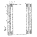
- a length of pipe indicated generally at 10 is produced by winding a plurality of layers onto a heated rotating mandrel 12.
- the mandrel is coated with a known release agent (not shown).
- a resin rich inner surface 14 is provided by helically wrapping a "C" glass or polyester veil onto the mandrel and impregnating with a suitable epoxy resin such as MY 750 supplied by the Ciba-Geigy company with a suitable hardener system. Successive helical turns of the veil material are overlapped in the axial direction, the width of the veil material being about 150mm.
- a suitable epoxy resin such as MY 750 supplied by the Ciba-Geigy company with a suitable hardener system.
- a thickness of GRP inner lining 16 is then built up by helically applying filament windings from a creel 17 of "E" glass fibre filaments 18 laid at 55° to the tube axis.
- the filaments 18 are passed through a resin bath (not shown) immediately prior to winding so that the windings are effectively provided with a resin matrix as they are being wound.
- a number of filament rovings are laid such that the minimum thickness is about 2mm.
- Prepared steel strip 20 from coils 22 is then helically wound onto the still uncured wet resin of the inner lining 16, successive helical turns lying adjacent each other with a maximum axial gap 24 of 5mm.
- An epoxy resin 26 containing an appropriate filler is simultaneously applied by known means to the steel strip as it is wound onto the pipe such that in the finished pipe, each layer of steel is coated with and bonded to the next layer by the resin system.
- the number steel layers and the total thickness is determined by the required pressure, stiffness rating and diameter of the pipe and the combined mechanical properties of the steel and linings.
- the helical windings of the steel strips are axially offset to each other so that there is no right line path from the inside to the outside of the tube through more than one of the axial gaps 26, and as indicated by the dashed line 28.
- An outer lining 30 is applied by a number of rovings of 55° helical windings of an "E" glass fibre filament 32 from a creel 34. As with the inner lining, the filament 32 is passed through a resin bath (not shown) immediately prior to winding. The thickness of the outer lining 30 is a minimum of 1mm.
- the mandrel with gelled or cured pipe assembly is removed from the winding machine (not shown) and allowed to cool to ambient temperature whereupon the mandrel is removed from the pipe.
- the pipe may then be post-cured in a free standing position if required. After cooling to ambient temperature, the pipe is cut to finished length by grinding through the total wall thickness, ie GRP and steel, to remove a minimum of two pitch lengths of steel from each end.
Landscapes
- Engineering & Computer Science (AREA)
- General Engineering & Computer Science (AREA)
- Mechanical Engineering (AREA)
- Rigid Pipes And Flexible Pipes (AREA)
- Laminated Bodies (AREA)
- Lining Or Joining Of Plastics Or The Like (AREA)
- Moulding By Coating Moulds (AREA)
- Joints Allowing Movement (AREA)
- Supports For Pipes And Cables (AREA)
Claims (28)
- Tube (10) comportant des revêtements interne (16) et externe (30) en matière plastique renforcée par des fibres, les revêtements interne et externe englobant des fibres continues et possédant entre eux une partie centrale constituée d'un ruban en acier (20) enroulé en spirales, le ruban en acier étant enrobé dans une matrice (26) en matière plastique, caractérisé en ce que les revêtements interne et externe comprennent chacun plusieurs couches d'enroulements filamentaires de fibres continues (18, 32) dans une matrice en matière plastique, les filaments de chacune desdites couches s'étendant dans une direction circonférentielle uniquement et l'ensemble desdits filaments dans chaque couche étant sensiblement parallèles l'un à l'autre et s'étendant dans la même direction circonférentielle.
- Tube selon la revendication 1, dans lequel les enroulements filamentaires sont des monofilaments.
- Tube selon la revendication 1, dans lequel les enroulements filamentaires sont des torons à multifilaments.
- Tube selon l'une quelconque des revendications précédentes, dans lequel des couches alternées d'enroulements filamentaires sont posées en formant des angles positif et négatif différents par rapport à l'axe du tube.
- Tube selon l'une quelconque des revendications précédentes 1 à 3, dans lequel des couches alternées d'enroulements filamentaires sont posées en formant des angles positif et négatif différents les uns par rapport aux autres.
- Tube selon l'une quelconque des revendications précédentes 1 à 3, dans lequel les enroulements filamentaires sont posés en formant un angle de + et -55° par rapport à l'axe du tube.
- Tube selon la revendication 6, dans lequel la marge d'erreur de l'angle formé par les enroulements filamentaires est de + ou - 5°.
- Tube selon l'une quelconque des revendications précédentes, englobant en outre un revêtement imperméable à l'intérieur de la matière de revêtement interne à enroulement filamentaire.
- Tube selon la revendication 8, dans lequel le revêtement imperméable est choisi parmi une matière choisie parmi le groupe comprenant l'aluminium, des matières plastiques thermodurcissables et du caoutchouc de silicone.
- Tube selon l'une quelconque des revendications précédentes, dans lequel la matière de revêtement à enroulement filamentaire est au moins choisie parmi le groupe comprenant des fibres de verre, des fibres d'aramide et des fibres de carbone.
- Tube selon l'une quelconque des revendications précédentes, dans lequel le revêtement interne à enroulement filamentaire possède une épaisseur minimale de 2 mm.
- Tube selon l'une quelconque des revendications précédentes, dans lequel le revêtement externe à enroulement filamentaire possède une épaisseur minimale de 1 mm.
- Tube selon l'une quelconque des revendications précédentes, dans lequel la partie centrale constituée d'un ruban d'acier enroulé en spirales comprend plusieurs couches de ruban enroulées en spirales disposées en contact jointif.
- Tube selon l'une quelconque des revendications précédentes de 1 à 12, dans lequel la partie centrale constituée du ruban d'acier enroulé en spirales comprend au moins un ruban dont les spires successives se chevauchent dans les directions axiale et radiale.
- Tube selon l'une quelconque des revendications précédentes 1 à 13, dans lequel le modèle d'enroulement des rubans d'acier est arrangé de telle sorte qu'aucun espace libre axial ménagé entre des bords adjacents du ruban enroulé dans une quelconque couche ne coïncide en direction radiale avec l'espace libre axial ménagé dans n'importe quelle autre couche.
- Tube selon l'une quelconque des revendications précédentes 1 à 13, dans lequel le modèle d'enroulement des rubans d'acier se répète en direction radiale.
- Tube selon l'une quelconque des revendications précédentes 1 à 13 et 15 à 16, dans lequel l'espace libre ménagé entre des bords adjacents de spires successives représente au maximum 5 mm.
- Tube selon l'une quelconque des revendications précédentes 1 à 13 et 15 à 17, dans lequel l'espace libre ménagé entre des bords adjacents de spires successives se situe dans le domaine de 1 mm à 3 mm.
- Tube selon l'une quelconque des revendications précédentes, dans lequel la matrice en matière plastique est une résine époxy.
- Tube selon l'une quelconque des revendications précédentes, dans lequel la résine en matière plastique englobe également une matière de charge.
- Tube selon l'une quelconque des revendications précédentes, dans lequel la largeur du ruban d'acier de la partie centrale se situe dans le domaine de 50 mm à 250 mm.
- Tube selon l'une quelconque des revendications précédentes, dans lequel l'épaisseur du ruban d'acier de la partie centrale se situe dans le domaine de 0,12 à 1 mm.
- Tube selon l'une quelconque des revendications précédentes, dans lequel son diamètre se situe dans le domaine d'environ 150 mm à environ 1000 mm.
- Tube selon l'une quelconque des revendications précédentes, dans lequel la capacité de déformation des revêtements en réponse à une pression interne croissante s'exerçant à l'intérieur du tube est telle que les revêtements manifestent une défaillance, et par conséquent manifestent un mode de défaillance par fuite, uniquement après que la partie centrale en acier a été soumise à une charge qui représente une proportion importante de la charge liée à sa déformation à la rupture.
- Tube selon la revendication 24, dans lequel la capacité de déformation à la pression manifestée par les revêtements est telle que ces derniers fournissent un mode de défaillance par fuite sous une pression interne prédéterminée après que la partie centrale en acier a subi une charge dépassant sa limite d'élasticité.
- Procédé de fabrication d'un tube (10), le procédé comprenant les étapes consistant à former un revêtement interne (16) en enroulant plusieurs couches d'une matière de fibres continues (18) sur un mandrin (12) en formant un angle prédéterminé par rapport à l'axe du tube; procurer une matrice de résine pour la couche fibreuse; enrouler en spirales une partie centrale constituée d'un ruban d'acier (20) sur ledit revêtement interne en matière fibreuse; munir ladite partie centrale constituée d'un ruban d'acier d'une matrice de résine (26); former un revêtement externe (30) en enroulant plusieurs couches d'une matière fibreuse (32) sur le côté externe de la partie centrale en formant un angle prédéterminé par rapport à l'axe du tube; munir ladite couche externe en matière fibreuse d'une matrice de résine; durcir au moins partiellement ladite matrice de résine et retirer ledit tube dudit mandrin, ledit procédé étant caractérisé par le fait d'enrouler une matière filamentaire de fibres continues (18, 32) dans une direction circonférentielle de telle sorte que l'ensemble desdits filaments dans chaque couche sont parallèles l'un à l'autre et que l'ensemble des filaments s'étendent dans la même direction circonférentielle dans chaque couche.
- Procédé selon la revendication 26, dans lequel ladite partie centrale en acier est réalisée en enroulant en spirales au moins trois couches d'un ruban d'acier.
- Procédé selon l'une quelconque des revendications 26 ou 27, dans lequel on forme les revêtements interne et externe en faisant passer ladite matière fibreuse à travers un bain de résine avant l'enroulement.
Applications Claiming Priority (5)
| Application Number | Priority Date | Filing Date | Title |
|---|---|---|---|
| GB929225658A GB9225658D0 (en) | 1992-12-08 | 1992-12-08 | Improvements in or relating to couplings for pipes and tubes |
| GB9225658 | 1992-12-08 | ||
| GB939303282A GB9303282D0 (en) | 1992-12-08 | 1993-02-18 | Pipe construction |
| GB9303282 | 1993-02-18 | ||
| PCT/GB1993/002483 WO1994013992A1 (fr) | 1992-12-08 | 1993-12-02 | Structure de canalisation |
Publications (2)
| Publication Number | Publication Date |
|---|---|
| EP0625251A1 EP0625251A1 (fr) | 1994-11-23 |
| EP0625251B1 true EP0625251B1 (fr) | 1998-02-11 |
Family
ID=26302126
Family Applications (1)
| Application Number | Title | Priority Date | Filing Date |
|---|---|---|---|
| EP94900966A Expired - Lifetime EP0625251B1 (fr) | 1992-12-08 | 1993-12-02 | Structure de tuyau |
Country Status (13)
| Country | Link |
|---|---|
| US (3) | US5636878A (fr) |
| EP (1) | EP0625251B1 (fr) |
| JP (1) | JP3735113B2 (fr) |
| CN (1) | CN1037467C (fr) |
| AT (1) | ATE163216T1 (fr) |
| AU (1) | AU667610B2 (fr) |
| CA (1) | CA2129636C (fr) |
| DE (1) | DE69316975T2 (fr) |
| DK (1) | DK0625251T3 (fr) |
| DZ (1) | DZ1734A1 (fr) |
| ES (1) | ES2112512T3 (fr) |
| RU (1) | RU2121101C1 (fr) |
| WO (1) | WO1994013992A1 (fr) |
Cited By (1)
| Publication number | Priority date | Publication date | Assignee | Title |
|---|---|---|---|---|
| DE10238103C1 (de) * | 2002-08-16 | 2003-09-18 | Kanal Und Rohrtechnik Gmbh | Verbundrohr und Verfahren zu seiner Herstellung |
Families Citing this family (67)
| Publication number | Priority date | Publication date | Assignee | Title |
|---|---|---|---|---|
| WO1994013993A1 (fr) * | 1992-12-08 | 1994-06-23 | Royal Ordnance Plc | Raccord de conduits |
| US5520422A (en) * | 1994-10-24 | 1996-05-28 | Ameron, Inc. | High-pressure fiber reinforced composite pipe joint |
| AU673325B3 (en) * | 1996-02-14 | 1996-10-31 | Ameron, Inc. | High-pressure fiber reinforced composite pipe joint |
| US5862303A (en) * | 1996-05-17 | 1999-01-19 | Advanced Metal Technologies, Ltd. | Electrically heated pipe with helically wound amorphous alloy heater |
| US5816625A (en) * | 1997-08-14 | 1998-10-06 | Clarke; Robert H. | Quick release coupling with spacer ring to align spline rod |
| US6692041B1 (en) * | 1997-10-06 | 2004-02-17 | Weldbend Corporation | Piping to component connector |
| RU2235936C2 (ru) * | 1998-11-17 | 2004-09-10 | Амерон Интернэшнл Корпорейшн | Способ образования многослойной трубы из стальных полос и многослойная труба |
| AU780180B2 (en) | 1999-11-05 | 2005-03-03 | Prime Flexible Products, Inc. | Flexible pipe and method of manufacturing same |
| JP3428547B2 (ja) * | 2000-01-20 | 2003-07-22 | 本田技研工業株式会社 | パイプの補強構造 |
| JP2001235070A (ja) * | 2000-02-24 | 2001-08-31 | Kakuichi Technical Service Kk | 可撓管、および可撓管の製造方法 |
| JP2001239900A (ja) * | 2000-02-29 | 2001-09-04 | Sumitomo Wiring Syst Ltd | 車体と可動体との間のワイヤハーネス配索構造 |
| DE10026272B4 (de) * | 2000-05-26 | 2007-12-13 | Siemens Ag | Hochdruckspeicher, insbesondere Kraftstoffhochdruckspeicher und Verfahren zur Herstellung eines Hochdruckspeichers |
| US6893733B2 (en) | 2000-07-07 | 2005-05-17 | Delphi Technologies, Inc. | Modified contoured crushable structural members and methods for making the same |
| US6949282B2 (en) | 2000-07-07 | 2005-09-27 | Delphi Technologies, Inc. | Contoured crushable composite structural members and methods for making the same |
| US6586110B1 (en) | 2000-07-07 | 2003-07-01 | Delphi Technologies, Inc. | Contoured metal structural members and methods for making the same |
| US6620475B1 (en) | 2000-08-10 | 2003-09-16 | Hydril Company | Structure for wound fiber reinforced plastic tubing and method for making |
| US6361080B1 (en) | 2000-08-23 | 2002-03-26 | Hydril Company | Method for attaching an ANSI stub-end flanged connector to a composite tubular member |
| US6688339B2 (en) * | 2000-08-29 | 2004-02-10 | Sekisui Chemical Co., Ltd. | Composite high-pressure tube and method of manufacturing the tube |
| US6672627B1 (en) * | 2001-02-14 | 2004-01-06 | Deere & Company | Lightweight air coupler |
| DE20109255U1 (de) * | 2001-06-01 | 2001-08-30 | SKP Konstruktion und Service GmbH, 88699 Frickingen | Kupplung zur koaxialen Verbindung, insbesondere von Schlauchleitungen |
| FR2834039B1 (fr) * | 2001-12-21 | 2004-02-13 | Inst Francais Du Petrole | Conduite flexible a haute resistance a la compression axiale et sa methode de fabrication |
| US6851643B2 (en) * | 2003-01-27 | 2005-02-08 | Sonoco Development, Inc. | Spirally wound tube with enhanced inner diameter stiffness, and method of making same |
| DE602004003372T2 (de) * | 2003-05-12 | 2007-09-13 | Putzmeister Inc., Sturtevant | Fasergewickeltes verbundauslegerrohr |
| DE10326933B4 (de) * | 2003-06-16 | 2005-07-14 | Audi Ag | Kraftstoffhochdruckspeicher für eine mehrzylindrige Brennkraftmaschine |
| US20050100414A1 (en) * | 2003-11-07 | 2005-05-12 | Conocophillips Company | Composite riser with integrity monitoring apparatus and method |
| US20050244216A1 (en) * | 2004-04-29 | 2005-11-03 | Michael Magraw | Coupler |
| RU2272953C1 (ru) * | 2004-09-30 | 2006-03-27 | Общество с ограниченной ответственностью "Научно-производственное объединение САМОС" | Способ изготовления трубы |
| ITFI20040202A1 (it) * | 2004-09-30 | 2004-12-30 | Perini Fabio Spa | Camicia intercambiabile per rulli goffratori o simili, metodo per la sua realizzazione, e rullo comprendente detta camicia |
| DE102005023148B4 (de) * | 2005-05-13 | 2009-07-30 | Airbus Deutschland Gmbh | Rohrleitung zur Durchleitung von Luft zur Klimatisierung in Luftfahrzeugen |
| JP2007073623A (ja) * | 2005-09-05 | 2007-03-22 | Kobe Steel Ltd | 超電導コイル製造用巻枠および超電導ソレノイド巻コイル |
| DE102006017004B3 (de) * | 2006-04-11 | 2007-10-25 | Airbus Deutschland Gmbh | Vorrichtung zur Vermischung von Frischluft und Heizluft sowie Verwendung derselben in einem Belüftungssystem eines Flugzeuges |
| CN100482999C (zh) * | 2006-04-12 | 2009-04-29 | 埃姆斯化学公司 | 管道的连接装置 |
| RU2009141990A (ru) * | 2007-04-16 | 2011-05-27 | Шелл Интернэшнл Рисерч Маатсхаппий Б.В. (NL) | Трубчатое тело, содержащее два или более слоя спирально выгнутых полос |
| BRPI0810610B1 (pt) * | 2007-04-27 | 2018-12-04 | Alcoa Inc | seção de tubo ascendente para perfuração de metal em alto mar e aparelho de tubo ascendente para uso em perfuração em alto mar para óleo ou outros combustíveis fósseis |
| RU2474745C2 (ru) * | 2007-05-04 | 2013-02-10 | Шелл Интернэшнл Рисерч Маатсхаппий Б.В. | Производство трубчатого тела, содержащего два или более слоя спирально выгнутых полос |
| DE102007022520A1 (de) * | 2007-05-14 | 2008-11-20 | Siemens Ag | Kühlmittelschlauch |
| US20090139708A1 (en) * | 2007-06-06 | 2009-06-04 | Baker Hughes Incorporated | Wrap-On Reactive Element Barrier Packer and Method of Creating Same |
| WO2009034155A1 (fr) * | 2007-09-13 | 2009-03-19 | Shell Internationale Research Maatschappij B.V. | Unité mobile destinée à la construction de corps tubulaires allongés |
| US20110188940A1 (en) * | 2007-12-18 | 2011-08-04 | Graham Dudley Freeth | Method for the construction of a long pipeline |
| US20090159145A1 (en) * | 2007-12-19 | 2009-06-25 | Caterpillar Inc. | Hose with composite layer |
| AR072415A1 (es) * | 2008-07-02 | 2010-08-25 | Shell Int Research | Un proceso para la elaboracion de un tubo elongado |
| WO2010026751A1 (fr) * | 2008-09-04 | 2010-03-11 | 横浜ゴム株式会社 | Procédé de fabrication d'un tuyau en caoutchouc renforcé par des câbles d'acier, et tuyau en caoutchouc renforcé par des câbles d'acier |
| US8444188B2 (en) * | 2008-11-09 | 2013-05-21 | Illinois Tool Works Inc. | Adapter |
| US9441766B2 (en) * | 2009-06-02 | 2016-09-13 | Bhp Billiton Petroleum Pty Ltd. | Reinforced hose |
| JP2011098523A (ja) * | 2009-11-06 | 2011-05-19 | Ihi Corp | ケースの製造方法、及びケース |
| US20110290411A1 (en) * | 2010-05-27 | 2011-12-01 | Pipestream B.V. | Modular System for Fabricating a Reinforced Tubular |
| JP5798805B2 (ja) * | 2011-06-07 | 2015-10-21 | 株式会社ブリヂストン | 高圧ホース |
| FR2978692B1 (fr) * | 2011-08-04 | 2013-09-06 | Snecma | Dispositif pour l'aide a la decoupe d'une couche de texture fibreuse enroulee sur un mandrin d'impregnation d'une machine d'enroulement |
| US8528121B2 (en) | 2011-12-14 | 2013-09-10 | Kohler Co. | Urinal bracket |
| US8910669B2 (en) | 2012-02-23 | 2014-12-16 | Ticona Llc | Insert for pipe assembly and method for forming pipe assembly |
| US20130241191A1 (en) * | 2012-03-16 | 2013-09-19 | J-M Manufacturing Company, Inc. | Pressure-rated spline joint |
| US10401086B2 (en) | 2013-01-15 | 2019-09-03 | Illinois Tool Works Inc. | Air manifold for drying a container |
| CN103195987B (zh) * | 2013-04-17 | 2014-10-29 | 孔少云 | 一种超高环刚度塑钢复合管及其制备方法 |
| US20150167868A1 (en) * | 2013-12-17 | 2015-06-18 | Scott Boncha | Maple sap vacuum collection systems with chew proof tubing |
| JP6340833B2 (ja) * | 2014-03-06 | 2018-06-13 | 新日鐵住金株式会社 | 鋼管杭の継手構造 |
| ES2732281T3 (es) * | 2014-10-24 | 2019-11-21 | Ocv Intellectual Capital Llc | Composición de tejidos asimétricos para aplicaciones de bobinado para volver a revestir tuberías |
| GB201421801D0 (en) * | 2014-12-08 | 2015-01-21 | Ge Oil & Gas Uk Ltd | Layer Repair |
| DE102015100797B4 (de) * | 2015-01-20 | 2021-01-07 | Ford-Werke Gmbh | Plastiklenksäule |
| EA029807B1 (ru) * | 2016-05-30 | 2018-05-31 | Павел Иванович Кичигин | Устройство для подземной транспортировки или хранения |
| CN106051327A (zh) * | 2016-06-29 | 2016-10-26 | 无锡必胜必精密钢管有限公司 | 一种用于传动轴的钢管 |
| US11148390B2 (en) | 2016-11-09 | 2021-10-19 | Lockheed Martin Corporation | Multiple layer hollow cylinder and method of making |
| CN106808707B (zh) * | 2017-03-27 | 2023-08-25 | 福建路通复合材料技术研究院有限公司 | 连续缠绕玻璃钢管生产工艺及其生产线 |
| CN107127985B (zh) * | 2017-05-25 | 2018-12-28 | 南京工程学院 | 一种纤维金属超混杂复合管的成形方法 |
| US10919106B2 (en) * | 2017-06-09 | 2021-02-16 | General Electric Company | Ultrasonic welding of annular components |
| CN107825684B (zh) * | 2017-10-26 | 2023-07-21 | 福州森百德机电科技有限公司 | 管道成型机及其工作方法 |
| CN110468370A (zh) * | 2019-08-20 | 2019-11-19 | 严克飞 | 不锈钢的表面处理方法 |
| JP7427197B2 (ja) * | 2020-06-10 | 2024-02-05 | 日本製鉄株式会社 | パイプ連結構造 |
Family Cites Families (41)
| Publication number | Priority date | Publication date | Assignee | Title |
|---|---|---|---|---|
| US1314670A (en) * | 1919-09-02 | Reinforced hard-rubber pipe | ||
| US1281557A (en) * | 1913-12-31 | 1918-10-15 | Howard W Goodall | Hose. |
| DE352812C (de) * | 1919-03-19 | 1922-05-04 | Blaisdell Petro Flex Tubing Co | Schlauch fuer Petroleum, OEl u. dgl. |
| US2371971A (en) * | 1943-04-26 | 1945-03-20 | Michigan Patents Corp | Hose connector |
| US2640501A (en) * | 1946-12-24 | 1953-06-02 | Int Standard Electric Corp | Tube and its manufacture |
| US2573361A (en) * | 1947-02-13 | 1951-10-30 | Libbey Owens Ford Glass Co | Torsion transmitting glass shaft and method of manufacture |
| US2807282A (en) * | 1954-02-17 | 1957-09-24 | Union Carbide Corp | Reinforced carbonaceous pipe and method of making same |
| GB966772A (en) * | 1961-08-16 | 1964-08-19 | Montaplast G M B H | Pipe joint |
| US3407251A (en) * | 1965-11-29 | 1968-10-22 | William I. Elliott | Method for forming cooperatively threaded parts |
| US3616123A (en) * | 1968-01-29 | 1971-10-26 | Johns Manville | Helicoid laminate comprising several continuous tiered strips |
| US3540757A (en) * | 1968-02-29 | 1970-11-17 | Ciba Geigy Corp | Pipe joint and method of forming a pipe joint |
| AT297424B (de) * | 1968-07-22 | 1972-03-27 | Industriebedarf Ges M B H | Rohrmuffenverbindung |
| GB1294658A (en) * | 1968-11-13 | 1972-11-01 | British Aircraft Corp Ltd | Improvements to pipe joints |
| US3578029A (en) * | 1969-06-27 | 1971-05-11 | Youngstown Sheet And Tube Co | Pipe |
| US3606402A (en) * | 1969-07-02 | 1971-09-20 | Fiberglass Resources Corp | Locking means for adjacent pipe sections |
| GB1356791A (en) * | 1970-01-26 | 1974-06-12 | Dunlop Holdings Ltd | Hose pipes |
| GB1273932A (en) * | 1971-04-21 | 1972-05-10 | Hepworth Iron Co Ltd | Improvements in or relating to pipe couplings |
| GB1277385A (en) * | 1971-04-21 | 1972-06-14 | Hepworth Iron Co Ltd | Improvements in or relating to pipe couplings |
| US3915776A (en) * | 1971-07-12 | 1975-10-28 | Kaempen Industries | Method for making composite structures |
| US3784441A (en) * | 1971-07-12 | 1974-01-08 | Kaempen Industries | Composite structure |
| US3957416A (en) * | 1971-07-12 | 1976-05-18 | Kaempen Industries, Inc. | Apparatus for making composite structures |
| US3790438A (en) * | 1971-12-28 | 1974-02-05 | Monsanto Co | Ribbon-reinforced composites |
| US3859701A (en) * | 1972-02-11 | 1975-01-14 | Armstrong Cork Co | Bonding of rubber to magnesium and its alloys |
| FR2203044B1 (fr) * | 1972-10-12 | 1976-11-19 | Battelle Memorial Institute | |
| USRE31047E (en) * | 1975-06-06 | 1982-10-05 | The Goodyear Tire & Rubber Company | Hose structure |
| US4216803A (en) * | 1976-06-15 | 1980-08-12 | Martin Marietta Corporation | Self-sealing fuel lines |
| US4111469A (en) * | 1976-12-23 | 1978-09-05 | Samuel Moore And Company | Hydraulic hose and coupling assembly |
| NL166304C (nl) * | 1977-02-23 | 1981-07-15 | Vredestein Nv | Buis voor het transport van een mengsel van vloeistof en vast materiaal. |
| US4156540A (en) * | 1977-08-30 | 1979-05-29 | Parker-Hannifin Corporation | Sealant for hose fittings |
| US4351364A (en) * | 1979-11-05 | 1982-09-28 | Dunlop Limited | Steel reinforced pipe |
| BE886312A (fr) * | 1980-11-24 | 1981-05-25 | Owens Corning Fiberglas Europ | Tuyau en resine thermodurcissable renforcee de fibres de verre et comportant un revetement interieur en aluminium, notamment pour le transport de l'eau chaude |
| GB2112095B (en) * | 1981-12-22 | 1985-02-06 | Rolls Royce | Joining components having different thermal expansion coefficients |
| ATE37437T1 (de) * | 1984-02-20 | 1988-10-15 | Fischer Ag Georg | Flanschverbindung fuer faserverstaerkte kunststoffrohrteile. |
| ATE36746T1 (de) * | 1984-02-20 | 1988-09-15 | Fischer Ag Georg | Verbindung fuer faserverstaerkte kunststoffrohre. |
| JPS62264610A (ja) * | 1986-05-13 | 1987-11-17 | Mitsubishi Electric Corp | コイルの巻線方法 |
| SE465230B (sv) * | 1987-06-16 | 1991-08-12 | Asea Plast Ab | Foerbindning foer tvaa roer av med ett fibermaterial armerad plast |
| FR2637952B1 (fr) * | 1988-10-13 | 1991-01-04 | Aerospatiale | Dispositif de liaison des extremites d'un tube composite fortement sollicite axialement avec des brides metalliques et son procede de fabrication |
| US5188273A (en) * | 1989-02-03 | 1993-02-23 | Helmuth Schmoock | Expander roller for webs of paper and the like |
| US5160688A (en) * | 1989-09-27 | 1992-11-03 | Continuous Hose Corporation | Method of making a component pipe coupling |
| NL9001384A (nl) * | 1990-06-18 | 1992-01-16 | Wavin Bv | Meerlaagse buis, leiding uit meerdere van dergelijke buizen en werkwijze voor het gas- en vloeistofdicht verbinden van twee van dergelijke buizen. |
| US5152556A (en) * | 1990-12-24 | 1992-10-06 | Kaiser Aerospace And Electronics Corporation | High temperature tubing joint with threaded, split collar |
-
1993
- 1993-12-02 EP EP94900966A patent/EP0625251B1/fr not_active Expired - Lifetime
- 1993-12-02 WO PCT/GB1993/002483 patent/WO1994013992A1/fr not_active Ceased
- 1993-12-02 US US08/284,452 patent/US5636878A/en not_active Expired - Fee Related
- 1993-12-02 JP JP51391494A patent/JP3735113B2/ja not_active Expired - Lifetime
- 1993-12-02 ES ES94900966T patent/ES2112512T3/es not_active Expired - Lifetime
- 1993-12-02 RU RU94044451A patent/RU2121101C1/ru active
- 1993-12-02 CA CA002129636A patent/CA2129636C/fr not_active Expired - Lifetime
- 1993-12-02 US US08/284,451 patent/US5579809A/en not_active Expired - Lifetime
- 1993-12-02 AU AU55729/94A patent/AU667610B2/en not_active Expired
- 1993-12-02 DK DK94900966.6T patent/DK0625251T3/da active
- 1993-12-02 DE DE69316975T patent/DE69316975T2/de not_active Expired - Lifetime
- 1993-12-02 AT AT94900966T patent/ATE163216T1/de active
- 1993-12-07 CN CN93121133A patent/CN1037467C/zh not_active Expired - Lifetime
- 1993-12-08 DZ DZ930129A patent/DZ1734A1/fr active
-
1995
- 1995-05-16 US US08/442,109 patent/US6048428A/en not_active Expired - Lifetime
Cited By (1)
| Publication number | Priority date | Publication date | Assignee | Title |
|---|---|---|---|---|
| DE10238103C1 (de) * | 2002-08-16 | 2003-09-18 | Kanal Und Rohrtechnik Gmbh | Verbundrohr und Verfahren zu seiner Herstellung |
Also Published As
| Publication number | Publication date |
|---|---|
| RU2121101C1 (ru) | 1998-10-27 |
| DZ1734A1 (fr) | 2002-02-17 |
| DE69316975D1 (de) | 1998-03-19 |
| DK0625251T3 (da) | 1998-05-11 |
| US6048428A (en) | 2000-04-11 |
| RU94044451A (ru) | 1996-06-20 |
| ES2112512T3 (es) | 1998-04-01 |
| CN1093785A (zh) | 1994-10-19 |
| CA2129636C (fr) | 2007-01-30 |
| ATE163216T1 (de) | 1998-02-15 |
| CN1037467C (zh) | 1998-02-18 |
| CA2129636A1 (fr) | 1994-06-23 |
| AU5572994A (en) | 1994-07-04 |
| US5636878A (en) | 1997-06-10 |
| AU667610B2 (en) | 1996-03-28 |
| JPH08504020A (ja) | 1996-04-30 |
| JP3735113B2 (ja) | 2006-01-18 |
| US5579809A (en) | 1996-12-03 |
| WO1994013992A1 (fr) | 1994-06-23 |
| EP0625251A1 (fr) | 1994-11-23 |
| DE69316975T2 (de) | 1998-06-10 |
Similar Documents
| Publication | Publication Date | Title |
|---|---|---|
| US6048428A (en) | Pipe construction | |
| US4351364A (en) | Steel reinforced pipe | |
| AU658866B2 (en) | Flexible tubular structure | |
| US20160348839A1 (en) | High-pressure composite vessel and the method of manufacturing high-pressure composite vessel | |
| IL27800A (en) | Composite reinforced plastic pipe and method for fabricating this pipe | |
| DK2079573T3 (en) | Reinforced pipe made of polyethylene composite material and method of manufacture thereof | |
| WO2000070256A1 (fr) | Conduit composite souple et leger pour huile et gaz sous haute pression | |
| KR102805248B1 (ko) | 유체 저장용 압력 용기 | |
| RU2201550C2 (ru) | Отвод из композиционного материала и способ его изготовления | |
| EP1446603B1 (fr) | Conduite flexible a armature de traction | |
| JP3228368B2 (ja) | 可撓性流体輸送管の製造方法 | |
| WO2025096556A1 (fr) | Tuyau composite | |
| RU2154766C1 (ru) | Труба из композиционных материалов и способ ее изготовления | |
| EP3012503B1 (fr) | Composition de tissus asymétriques pour revêtement des pipelines | |
| JP7406603B2 (ja) | 曲管 | |
| AU2017206265A1 (en) | Ultrathin concrete composite pipe with oriented and localized fiber | |
| RU2285187C2 (ru) | Способ изготовления стеклопластиковой секции трубопровода | |
| SA94140699B1 (ar) | تصميم مقوى لأنبوبة مركبة | |
| RU2855609C1 (ru) | Износостойкая композитная труба | |
| SU1362408A3 (ru) | Способ усилени полого тела вращени типа трубопровода или емкости,работающего под давлением | |
| WO1994025789A1 (fr) | Ameliorations concernant la fabrication de structures tubulaires | |
| CA2106096A1 (fr) | Structure tubulaire flexible | |
| CN117948465A (zh) | 一种地埋用复合结构壁螺旋增强刚性缠绕管材及其加工方法 | |
| RU2365804C1 (ru) | Способ повышения герметичности труб |
Legal Events
| Date | Code | Title | Description |
|---|---|---|---|
| PUAI | Public reference made under article 153(3) epc to a published international application that has entered the european phase |
Free format text: ORIGINAL CODE: 0009012 |
|
| 17P | Request for examination filed |
Effective date: 19940727 |
|
| AK | Designated contracting states |
Kind code of ref document: A1 Designated state(s): AT BE CH DE DK ES FR GB GR IE IT LI LU MC NL PT SE |
|
| 17Q | First examination report despatched |
Effective date: 19951218 |
|
| GRAG | Despatch of communication of intention to grant |
Free format text: ORIGINAL CODE: EPIDOS AGRA |
|
| GRAH | Despatch of communication of intention to grant a patent |
Free format text: ORIGINAL CODE: EPIDOS IGRA |
|
| GRAH | Despatch of communication of intention to grant a patent |
Free format text: ORIGINAL CODE: EPIDOS IGRA |
|
| ITF | It: translation for a ep patent filed | ||
| GRAA | (expected) grant |
Free format text: ORIGINAL CODE: 0009210 |
|
| AK | Designated contracting states |
Kind code of ref document: B1 Designated state(s): AT BE CH DE DK ES FR GB GR IE IT LI LU MC NL PT SE |
|
| REF | Corresponds to: |
Ref document number: 163216 Country of ref document: AT Date of ref document: 19980215 Kind code of ref document: T |
|
| REG | Reference to a national code |
Ref country code: CH Ref legal event code: NV Representative=s name: A. BRAUN, BRAUN, HERITIER, ESCHMANN AG PATENTANWAE Ref country code: CH Ref legal event code: EP |
|
| ET | Fr: translation filed | ||
| REF | Corresponds to: |
Ref document number: 69316975 Country of ref document: DE Date of ref document: 19980319 |
|
| REG | Reference to a national code |
Ref country code: ES Ref legal event code: FG2A Ref document number: 2112512 Country of ref document: ES Kind code of ref document: T3 |
|
| REG | Reference to a national code |
Ref country code: DK Ref legal event code: T3 |
|
| REG | Reference to a national code |
Ref country code: PT Ref legal event code: SC4A Free format text: AVAILABILITY OF NATIONAL TRANSLATION Effective date: 19980226 |
|
| REG | Reference to a national code |
Ref country code: IE Ref legal event code: FG4D Free format text: 78863 |
|
| PG25 | Lapsed in a contracting state [announced via postgrant information from national office to epo] |
Ref country code: LU Free format text: LAPSE BECAUSE OF NON-PAYMENT OF DUE FEES Effective date: 19981202 |
|
| PLBE | No opposition filed within time limit |
Free format text: ORIGINAL CODE: 0009261 |
|
| STAA | Information on the status of an ep patent application or granted ep patent |
Free format text: STATUS: NO OPPOSITION FILED WITHIN TIME LIMIT |
|
| 26N | No opposition filed | ||
| PG25 | Lapsed in a contracting state [announced via postgrant information from national office to epo] |
Ref country code: MC Free format text: LAPSE BECAUSE OF NON-PAYMENT OF DUE FEES Effective date: 19990630 |
|
| REG | Reference to a national code |
Ref country code: GB Ref legal event code: IF02 |
|
| REG | Reference to a national code |
Ref country code: CH Ref legal event code: PFA Owner name: ROYAL ORDNANCE PLC Free format text: ROYAL ORDNANCE PLC#EUXTON LANE#EUXTON CHORLEY LANCASHIRE PR7 6AD (GB) -TRANSFER TO- ROYAL ORDNANCE PLC#EUXTON LANE#EUXTON CHORLEY LANCASHIRE PR7 6AD (GB) |
|
| REG | Reference to a national code |
Ref country code: CH Ref legal event code: PFA Owner name: BAE SYSTEMS LAND SYSTEMS (MUNITIONS & ORDNANCE) L Free format text: ROYAL ORDNANCE PLC#EUXTON LANE#EUXTON CHORLEY LANCASHIRE PR7 6AD (GB) -TRANSFER TO- BAE SYSTEMS LAND SYSTEMS (MUNITIONS & ORDNANCE) LIMITED#WARWICK HOUSE P.O. BOX 87 FARNBOROUGH AEROSPACE CENTRE#FARNBOROUGH, HAMPSHIRE GU14 6YU (GB) |
|
| REG | Reference to a national code |
Ref country code: FR Ref legal event code: CD Ref country code: FR Ref legal event code: CA |
|
| PGFP | Annual fee paid to national office [announced via postgrant information from national office to epo] |
Ref country code: DK Payment date: 20121219 Year of fee payment: 20 Ref country code: IE Payment date: 20121220 Year of fee payment: 20 Ref country code: CH Payment date: 20121221 Year of fee payment: 20 |
|
| PGFP | Annual fee paid to national office [announced via postgrant information from national office to epo] |
Ref country code: SE Payment date: 20121220 Year of fee payment: 20 Ref country code: GB Payment date: 20121220 Year of fee payment: 20 Ref country code: GR Payment date: 20121221 Year of fee payment: 20 Ref country code: IT Payment date: 20121221 Year of fee payment: 20 Ref country code: PT Payment date: 20120604 Year of fee payment: 20 Ref country code: ES Payment date: 20121217 Year of fee payment: 20 |
|
| PGFP | Annual fee paid to national office [announced via postgrant information from national office to epo] |
Ref country code: AT Payment date: 20121212 Year of fee payment: 20 |
|
| PGFP | Annual fee paid to national office [announced via postgrant information from national office to epo] |
Ref country code: DE Payment date: 20121220 Year of fee payment: 20 Ref country code: FR Payment date: 20130130 Year of fee payment: 20 Ref country code: BE Payment date: 20121219 Year of fee payment: 20 |
|
| PGFP | Annual fee paid to national office [announced via postgrant information from national office to epo] |
Ref country code: NL Payment date: 20121220 Year of fee payment: 20 |
|
| REG | Reference to a national code |
Ref country code: DE Ref legal event code: R071 Ref document number: 69316975 Country of ref document: DE |
|
| REG | Reference to a national code |
Ref country code: DK Ref legal event code: EUP Effective date: 20131202 |
|
| REG | Reference to a national code |
Ref country code: PT Ref legal event code: MM4A Free format text: MAXIMUM VALIDITY LIMIT REACHED Effective date: 20131202 |
|
| REG | Reference to a national code |
Ref country code: NL Ref legal event code: V4 Effective date: 20131202 |
|
| REG | Reference to a national code |
Ref country code: CH Ref legal event code: PL |
|
| REG | Reference to a national code |
Ref country code: GB Ref legal event code: PE20 Expiry date: 20131201 |
|
| BE20 | Be: patent expired |
Owner name: BAE SYSTEMS LAND SYSTEMS (MUNITIONS & ORDNANCE) LT Effective date: 20131202 |
|
| REG | Reference to a national code |
Ref country code: AT Ref legal event code: MK07 Ref document number: 163216 Country of ref document: AT Kind code of ref document: T Effective date: 20131202 |
|
| REG | Reference to a national code |
Ref country code: IE Ref legal event code: MK9A |
|
| PG25 | Lapsed in a contracting state [announced via postgrant information from national office to epo] |
Ref country code: PT Free format text: LAPSE BECAUSE OF EXPIRATION OF PROTECTION Effective date: 20131210 Ref country code: DE Free format text: LAPSE BECAUSE OF EXPIRATION OF PROTECTION Effective date: 20131203 Ref country code: GB Free format text: LAPSE BECAUSE OF EXPIRATION OF PROTECTION Effective date: 20131201 |
|
| REG | Reference to a national code |
Ref country code: SE Ref legal event code: EUG |
|
| REG | Reference to a national code |
Ref country code: GR Ref legal event code: MA Ref document number: 980401013 Country of ref document: GR Effective date: 20131203 |
|
| PG25 | Lapsed in a contracting state [announced via postgrant information from national office to epo] |
Ref country code: IE Free format text: LAPSE BECAUSE OF EXPIRATION OF PROTECTION Effective date: 20131202 |
|
| REG | Reference to a national code |
Ref country code: ES Ref legal event code: FD2A Effective date: 20140925 |
|
| PG25 | Lapsed in a contracting state [announced via postgrant information from national office to epo] |
Ref country code: ES Free format text: LAPSE BECAUSE OF EXPIRATION OF PROTECTION Effective date: 20131203 |