EP1446603B1 - Conduite flexible a armature de traction - Google Patents
Conduite flexible a armature de traction Download PDFInfo
- Publication number
- EP1446603B1 EP1446603B1 EP02803337A EP02803337A EP1446603B1 EP 1446603 B1 EP1446603 B1 EP 1446603B1 EP 02803337 A EP02803337 A EP 02803337A EP 02803337 A EP02803337 A EP 02803337A EP 1446603 B1 EP1446603 B1 EP 1446603B1
- Authority
- EP
- European Patent Office
- Prior art keywords
- tensile reinforcement
- flexible pipe
- elements
- filaments
- tensile
- Prior art date
- Legal status (The legal status is an assumption and is not a legal conclusion. Google has not performed a legal analysis and makes no representation as to the accuracy of the status listed.)
- Revoked
Links
Images

Classifications
-
- F—MECHANICAL ENGINEERING; LIGHTING; HEATING; WEAPONS; BLASTING
- F16—ENGINEERING ELEMENTS AND UNITS; GENERAL MEASURES FOR PRODUCING AND MAINTAINING EFFECTIVE FUNCTIONING OF MACHINES OR INSTALLATIONS; THERMAL INSULATION IN GENERAL
- F16L—PIPES; JOINTS OR FITTINGS FOR PIPES; SUPPORTS FOR PIPES, CABLES OR PROTECTIVE TUBING; MEANS FOR THERMAL INSULATION IN GENERAL
- F16L11/00—Hoses, i.e. flexible pipes
- F16L11/14—Hoses, i.e. flexible pipes made of rigid material, e.g. metal or hard plastics
- F16L11/16—Hoses, i.e. flexible pipes made of rigid material, e.g. metal or hard plastics wound from profiled strips or bands
-
- F—MECHANICAL ENGINEERING; LIGHTING; HEATING; WEAPONS; BLASTING
- F16—ENGINEERING ELEMENTS AND UNITS; GENERAL MEASURES FOR PRODUCING AND MAINTAINING EFFECTIVE FUNCTIONING OF MACHINES OR INSTALLATIONS; THERMAL INSULATION IN GENERAL
- F16L—PIPES; JOINTS OR FITTINGS FOR PIPES; SUPPORTS FOR PIPES, CABLES OR PROTECTIVE TUBING; MEANS FOR THERMAL INSULATION IN GENERAL
- F16L11/00—Hoses, i.e. flexible pipes
- F16L11/04—Hoses, i.e. flexible pipes made of rubber or flexible plastics
- F16L11/08—Hoses, i.e. flexible pipes made of rubber or flexible plastics with reinforcements embedded in the wall
- F16L11/081—Hoses, i.e. flexible pipes made of rubber or flexible plastics with reinforcements embedded in the wall comprising one or more layers of a helically wound cord or wire
- F16L11/083—Hoses, i.e. flexible pipes made of rubber or flexible plastics with reinforcements embedded in the wall comprising one or more layers of a helically wound cord or wire three or more layers
Definitions
- the invention relates to a flexible pipe, such as a reinforced flexible pipe of the type which is adapted to transport fluids between installations above and/or below sea level.
- the pipe comprises a tensile reinforcement comprising at least a layer of tensile reinforcement elements.
- Tensile reinforcements for flexible pipes of the above-mentioned type are known from several publications, including e.g. WO 00/36324 or WO 98/57085 .
- Such pipes often comprise a so-called carcass, whose outer side has arranged thereon an inner liner which in turn is surrounded by at least one, but frequently several outer reinforcement layers which impart resistance to the liner against an increase in the volume spanned by it.
- the liner may thus during layout and operation change its volume either as a consequence of the outer (e.g. hydrostatic) pressure or the inner pressure in the pipe, and/or as a consequence of tensile forces in the longitudinal direction of the pipe.
- the reinforcement layer or layers may thus be dimensioned to absorb compressive and/or tensile forces.
- One or more layers may be provided between the reinforcement layers or externally on these, whose function may be to impart thermal resistance to the pipe, so that exchange of thermal energy between the fluid transported in the pipe and the surroundings of the pipe is reduced.
- Another possible function may be to prevent migration of material inwards between the reinforcement elements.
- a third possibility is that the layers may absorb instantaneous hoop stresses in the liner material as a consequence of non-stationary operating conditions.
- the outer reinforcement layer may have arranged thereon an outer jacket whose purpose among other things is to protect the outer reinforcement layer against mechanical damage which may occur because of impact loads.
- This outer jacket may moreover be tight or permeable to external fluids, depending on the structure of the pipe.
- the above-mentioned type of pipes is primarily used for the transport of oil and gas at various depths e.g. for the transport between offshore installations.
- the reinforcement layers consist of solid tensile reinforcement elements, e.g. of steel, which are twisted or wound around the longitudinal axis of the pipe, where the reinforcement layers that absorb pressure are twisted at a great angle relative to the longitudinal axis of the pipe and mutually kept together by profiles, while the reinforcement layers that absorb tension are twisted or wound at a somewhat smaller angle relative to the longitudinal axis of the pipe, such as about 55°.
- the outermost reinforcement layer which is a tensile reinforcement layer, which is subjected to mechanical Impacts from blows and the like that can damage the pipe, since blows against the solid reinforcement elements may cause rupture of these.
- the outermost reinforcement layer which is a tensile reinforcement layer, which is subjected to mechanical Impacts from blows and the like that can damage the pipe, since blows against the solid reinforcement elements may cause rupture of these.
- US Patent Application No. 2001/0003992 describes a one-piece subsea flexible multilayer tubular pipe comprising a carcass made of interlocked metal strip, an inner sealing sheath made of a polymer material, a winding of an interlocked metal element wound in a helix with a short pitch, at least one ply of tensile armor layers wound with a long pitch around the pressure vault, where appropriate at least one thermal insulation layer and an outer protective sealing sheath.
- US-6,165,586 deals with a flexible flat strip and its use in a flexible duct.
- the flexible strip comprises 1) a layer of filamentary rovings arranged in a substantially rectangular cross section, 2) retaining means for surrounding and clamping the layer of rovings and 3) a binding material to bind the retaining means to the layer.
- the filamentary rovings may e.g. consist of a set or group of continuous threads twisted or not twisted together, each thread being capable of being a monofilament or a set of continuous or discontinuous fibres or filaments assembled, in particular, by twisting or spinning.
- a flexible duct comprising two superposed reinforcement layers using such a strip helically wound around the preceding layer is described.
- the presence of retaining means and binding material in the armouring wire or strip used for winding a reinforcement layer decreases the fraction of the cross section of the armouring wire or strip that contributes to its tensile strength.
- It is another object of the invention is to provide a flexible pipe that is simple to manufacture compared to the prior art.
- the invention thus relates to a flexible pipe for use in the transport of fluids between installations above and/or below sea level.
- the pipe comprises a tensile reinforcement having at least one tensile reinforcement layer.
- At least one of the tensile reinforcement layers comprises one or more tensile reinforcement elements, and at least one of said tensile reinforcement elements consists of compound filaments, said tensile reinforcement element or elements being wound around the pipe to form part of said tensile reinforcement layer.
- compound filaments' is in the present context taken to mean filaments in the form of threads or wires or fibres held together in that these threads or wires or fibres are woven, twisted, spun or entangled in each other to form threads.
- the tensile reinforcement of a flexible pipe for use in the transport of fluids comprises two or more tensile reinforcement layers, wherein at least one of the tensile reinforcement layers is made of one or preferably more tensile reinforcement elements consisting of filaments in the form of threads or wires held together in that these threads or wires are woven, twisted, spun or entangled in each other to form threads which constitute the tensile reinforcement elements, said tensile reinforcement element/elements being wound around the pipe to form a tensile reinforcement layer.
- the tensile reinforcement may have several tensile reinforcement layers, such as 2, 3, 4, 5 or more.
- the tensile reinforcement layers are preferably not bonded to each other, so that the individual tensile reinforcement layers may be displaced relative to each other when the pipe is bent, e.g. when it is wound on a transport drum or reel.
- the flexibility of a spin-built tensile reinforcement layer is somewhat greater than if solid elements are involved.
- At least one of the tensile reinforcement layers and preferably more or all of the layers are made of one or preferably more tensile reinforcement elements in the form of filaments held together, preferably compound filaments. Since the individual tensile reinforcement elements are formed by filaments held together, they will be able to better resist external mechanical impacts, thus eliminating the risk of through-going cuts.
- the filaments are preferably held together in that they are physically woven, twisted, spun or entangled in each other to form threads.
- no binding means such as glue or thermoplastic, etc.
- no retaining means such as a sheath or a thread or a tape, etc. surrounding some or all of the individual filaments of a reinforcement element are used. Both of these embodiments provide a simplified manufacture of the flexible pipe, making it more compact (for a given tensile strength) and potentially decreasing its cost.
- each of the filaments in a tensile reinforcement layer intersects at least one of the other elements for each longitudinal unit of the filament corresponding to 50-500 times the diameter of the filament, preferably for each longitudinal unit of the filament corresponding to 10-100 times the diameter of the filament.
- the filaments are preferably in the form of threads or wires or continuous or discontinuous fibres, and in principle they may have any thickness, the number of filaments in the individual tensile reinforcement layer being adapted relative to the thickness of the filaments.
- the filaments may e.g.
- the number of filaments per tensile reinforcement element may e.g. be between 10 and 5000, such as between 50 and 500 or alternatively between 100 (e.g. steel wire) and 5 000 000 (e.g. conventional rope).
- the tensile reinforcement element or elements are wound or twisted around the pipe to form a tensile reinforcement layer.
- the tensile reinforcement layers are made of tensile reinforcement elements consisting of filaments held together
- the tensile reinforcement layers are wound around the pipe to form independent tensile reinforcement layers.
- the winding angle may advantageously be different from layer to layer.
- the reinforcement element/elements are wound (e.g. in pairs) around the flexible pipe at an angle relative to the axis of the flexible pipe which is substantially identical in all windings. This makes it relatively easy to dimension the tensile reinforcement elements of existing flexible pipes to those identified according to the invention.
- substantially identical means in this connection that the angle from one winding to another winding is within 10 degrees, preferably within 5 degrees and in particular within 3 degrees.
- these tensile reinforcement elements are mechanically locked to each other, which may take place e.g. by weaving one or preferably more of the filaments from one reinforcement element into one or preferably more filaments from another reinforcement element into each other, as is known from ropes and cords.
- these tensile reinforcement elements are mechanically locked to each other, which may take place e.g. by weaving one or preferably more of the filaments from one reinforcement element into one or preferably more filaments from another reinforcement element into each other, as is known from ropes and cords.
- the interweaving of two fully crossing reinforcement elements may in a preferred embodiment take the form of an interweaving of the whole of the reinforcement elements with each other (i.e. in a crossing, all filaments of a first reinforcement element cross above (or alternatively all below) all filaments of a second reinforcement element).
- a crossing between two reinforcement elements of a reinforcement layer is characterized in that a fraction (e.g. approximately half) of the filaments of a first reinforcement layer cross above (or alternatively below) a fraction (e.g. half or all) of the filaments a second reinforcement element and the rest of the filaments of the first reinforcement layer (e.g. approximately half) cross below (or alternatively above) a fraction (e.g. half or all) of the filaments of the second reinforcement element.
- the tensile reinforcement elements may advantageously consist of two groups of tensile reinforcement elements, each group comprising at least one tensile reinforcement element, and where the tensile reinforcement elements of one group have a winding angle which is opposite to the winding angle of the other group, the filaments of the elements from one group being interwoven with the filaments of the elements from the other group.
- expedient selections of material for use as tensile reinforcement elements according to the invention may advantageously be as stated in the claims, i.e. be made entirely or partly of a composite material, of an Fe-based alloy containing at least 50% Fe, of a Ti-based alloy containing at least 50% Ti, an aramide or an aramide-like polymer, or a linearized or spun polyethylene having an ultra-high molecular weight.
- the filaments may alternatively be made of carbon, glass, polyethylene, a metallic or ceramic material, etc.
- the individual filaments are coated with another metal.
- the pipe according to the invention also comprises an end termination.
- the tensile reinforcement is composed of tensile reinforcement elements which are formed by filaments held together, the tensile reinforcement is easy to prepare for embedding in a coupling unit provided in the end termination, which may e.g. be formed with a plurality of holes through which the filaments, the threads or the wires may be passed for moulding on the coupling unit.
- a foreign member which may e.g. be in the form of a wedge, may be inserted between the filaments.
- a foreign member which may e.g. be in the form of a wedge, may be inserted between the filaments.
- two or more filaments, threads, or wires (or the whole tensile reinforcement element) may be passed through a hole in the coupling unit, and when the foreign member is arranged between the filaments, the threads or the wires, they (or the whole tensile reinforcement element) cannot possibly be pulled back through the hole after moulding, cf. e.g. WO-A1-01/07818 which is incorporated herein by reference.
- the numeral 1 generally designates a flexible pipe which is suitable for offshore use in connection with the extraction of oil and gas.
- the pipe has a duct 2 defined by a so-called carcass 3, which consists of profiled steel strips made by means of a carcass machine in which steel strips are profiled and subsequently wound to form the duct 2.
- carcass 3 which consists of profiled steel strips made by means of a carcass machine in which steel strips are profiled and subsequently wound to form the duct 2.
- the carcass per se is not tight, and to prevent flow of fluid out of the duct 2 or into the duct from the surroundings, a tight inner liner 4 is arranged externally on it.
- the main purpose of the carcass is to protect the inner liner against collapse because of a pressure applied to it from the surroundings.
- the inner liner has arranged externally thereon several reinforcement layers, including a pressure reinforcement 5, 6 which consists of assembled profiles, shown here as C-profiles.
- This pressure reinforcement may also be composed of profiles of another type.
- the pressure reinforcement has arranged externally thereon a tensile reinforcement 7, 8, which is arranged in two layers, as shown, where the pitch angle of the one layer is about 55° relative to the longitudinal axis of the pipe, and the pitch angle of the other layer is opposite, viz. -55° relative to the longitudinal axis of the pipe.
- a protective jacket here designated 9, is arranged externally on the outer tensile reinforcement layer.
- the tensile reinforcement elements 7, 8 consist of individual elements having the same geometrical shape, as is known from ordinary tensile reinforcement elements which are solid.
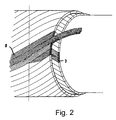
- the individual elements are made of filaments held together according to the invention, which may be woven into each other as shown in fig. 1, or be twisted together in a longitudinal direction as shown in fig. 2, so that the individual filaments are disposed side by side.
- the filaments are held together by being braided, twisted, spun or entangled or the like to form a reinforcement element without the use of any binding materials (such as glue or thermoplastic, etc.) or retaining elements (such as a sheath or a thread or a tape, etc.) surrounding some or all of the filaments of the reinforcement element.
- the individual reinforcement elements of a reinforcement layer are held together by interleaving without the use of any binding materials or retaining elements surrounding some or all of the reinforcement elements of the reinforcement layer in question.
- each of the woven armouring layers (7 or 8 in fig. 1) comprise a number of reinforcement elements wound at an angle ⁇ to the longitudinal axis of the pipe (type A) and a number of crossing reinforcement elements wound at an angle - ⁇ to the longitudinal axis of the pipe (type B).
- an armouring layer In a cross section perpendicular to the longitudinal direction of the pipe, an armouring layer consists of two crossing layers, of type A and type B reinforcement elements, 'on top of each other' when viewed in a radial direction in this cross section, so that a type A element is outermost in one segment and a type B element is outermost in its neighbouring segment to each side (i.e. alternating when viewed in a peripheral direction).
- fig. 1 it is only indicated that neighbouring segments have different cross sectional signatures alternating along the periphery of an armouring layer.
- the layered structure of each segment is, however, not indicated.
- the winding angle ⁇ may but need not be identical for the armouring layers (7, 8 in fig. 1).
- the invention thus provides a pipe having a tensile reinforcement which, in addition to being more resistant to mechanical external impacts, also imparts greater mechanical flexibility to the flexible pipe, other things being equal. Moreover, the tensile reinforcement elements on the pipe according to the invention are more suitable for being assembled in end terminations,
Landscapes
- Engineering & Computer Science (AREA)
- General Engineering & Computer Science (AREA)
- Mechanical Engineering (AREA)
- Rigid Pipes And Flexible Pipes (AREA)
- Tents Or Canopies (AREA)
- Apparatus For Making Beverages (AREA)
Claims (13)
- Conduite flexible (1) destinée à être utilisée dans le transport de fluides entre des installations au dessus et/ou en dessous du niveau de la mer, ladite conduite (1) comprenant une armature de traction dans laquelle l'armature de traction comprend une ou plusieurs couches (5, 6, 7, 8) d'armature de traction et qu'au moins une des couches (5, 6, 7, 8) d'armature de traction comprend un ou plusieurs éléments d'armature de traction, et au moins un desdits éléments d'armature de traction est constitué de filaments composés, ledit ou lesdits éléments d'armature de traction étant enroulé(s) pour faire partie de ladite couche (5, 6, 7, 8) d'armature de traction.
- Conduite flexible selon la revendication 1 dans laquelle toutes les couches (5, 6, 7, 8) d'armature de traction sont faites d'éléments d'armature de traction constitués de filaments composés, lesdits éléments d'armature de traction étant enroulés autour de la conduite pour former des couches (5, 6, 7, 8) indépendantes d'armature de traction.
- Conduite flexible selon la revendication 1 ou 2 dans laquelle les filaments sont tenus ensemble sans l'utilisation de matériaux de liaison.
- Conduite flexible selon l'une quelconque des revendications 1 à 3 dans laquelle les filaments sont tenus ensemble sans l'utilisation du moyen de retenue entourant certains ou la totalité des filaments.
- Conduite flexible selon l'une quelconque des revendications 1 à 4 dans laquelle le(s) élément/éléments à armature de traction sont enroulés autour de la conduite flexible au niveau d'un angle par rapport à l'axe de la conduite flexible qui est sensiblement identique dans tous les bobinages.
- Conduite flexible selon l'une quelconque des revendications 1 à 5 dans laquelle au moins une couche (5, 6, 7, 8) à armature de traction comprend plusieurs éléments à armature de traction, et où ces éléments à armature de traction sont verrouillés de manière mécanique les uns avec les autres.
- Conduite flexible selon l'une quelconque des revendications 1 à 6 dans laquelle les éléments à armature de traction sont faits en totalité ou en partie d'un matériau composite.
- Conduite flexible selon l'une quelconque des revendications 1 à 6 dans laquelle les éléments à armature de traction sont constitués d'un alliage à base de Fe contenant au moins 50 % de Fe.
- Conduite flexible selon l'une quelconque des revendications 1 à 6 dans laquelle les éléments à armature de traction sont constitués d'un alliage à base de Ti contenant au moins 50 % de Ti.
- Conduite flexible selon l'une quelconque des revendications 1 à 6 dans laquelle les éléments à armature de traction sont constitués d'une aramide ou d'un polymère ressemblant à une aramide.
- Conduite flexible selon l'une quelconque des revendications 1 à 6 dans laquelle les éléments à armature de traction sont faits d'un polyéthylène linéaire ayant un poids moléculaire ultra léger.
- Conduite flexible selon l'une quelconque des revendications 1 à 11 dans laquelle la conduite comprend un raccordement d'extrémité sous la forme d'une unité de couplage, les éléments individuels à armature de traction d'une couche (5, 6, 7, 8) à armature de traction étant fixés à l'unité de couplage en incorporant les éléments à armature de traction dans celle-ci.
- Conduite flexible selon la revendication 12 dans laquelle un élément de séparation est inséré entre les filaments des éléments à armature de traction.
Applications Claiming Priority (3)
| Application Number | Priority Date | Filing Date | Title |
|---|---|---|---|
| DKPA200101723 | 2001-11-19 | ||
| DK200101723 | 2001-11-19 | ||
| PCT/DK2002/000778 WO2003044414A1 (fr) | 2001-11-19 | 2002-11-19 | Conduite flexible a armature de traction |
Publications (2)
| Publication Number | Publication Date |
|---|---|
| EP1446603A1 EP1446603A1 (fr) | 2004-08-18 |
| EP1446603B1 true EP1446603B1 (fr) | 2008-01-09 |
Family
ID=8160846
Family Applications (1)
| Application Number | Title | Priority Date | Filing Date |
|---|---|---|---|
| EP02803337A Revoked EP1446603B1 (fr) | 2001-11-19 | 2002-11-19 | Conduite flexible a armature de traction |
Country Status (6)
| Country | Link |
|---|---|
| EP (1) | EP1446603B1 (fr) |
| AT (1) | ATE383539T1 (fr) |
| AU (1) | AU2002366056A1 (fr) |
| BR (1) | BR0214091B1 (fr) |
| DE (1) | DE60224559D1 (fr) |
| WO (1) | WO2003044414A1 (fr) |
Families Citing this family (8)
| Publication number | Priority date | Publication date | Assignee | Title |
|---|---|---|---|---|
| EP1663637B2 (fr) † | 2003-09-19 | 2018-07-25 | National Oilwell Varco Denmark I/S | Tuyau souple a structure partiellement non liee, et son procede de production |
| US7987875B2 (en) | 2004-07-08 | 2011-08-02 | Nkt Flexibles I/S | Flexible pipe, its manufacture and use |
| MX344217B (es) | 2009-12-28 | 2016-12-07 | Nat Oilwell Varco Denmark I/S * | Un tubo no ligado, flexible. |
| EP2593701A4 (fr) | 2010-07-14 | 2014-02-26 | Nat Oilwell Varco Denmark Is | Tuyau souple sans liaison |
| FR2994242B1 (fr) | 2012-08-03 | 2015-03-06 | Technip France | Conduite flexible sous marine comprenant une gaine polymerique interne et/ou externe d'etancheite comprenant un polyethylene a haut poids moleculaire |
| DK177627B1 (en) | 2012-09-03 | 2013-12-16 | Nat Oilwell Varco Denmark Is | An unbonded flexible pipe |
| FR3022320B1 (fr) | 2014-06-16 | 2016-07-29 | Technip France | Conduite tubulaire a bande de maintien composite |
| WO2017076412A1 (fr) | 2015-11-03 | 2017-05-11 | National Oilwell Varco Denmark I/S | Tuyau souple non collé |
Family Cites Families (5)
| Publication number | Priority date | Publication date | Assignee | Title |
|---|---|---|---|---|
| US4898212A (en) * | 1984-10-01 | 1990-02-06 | Eaton Corporation | Fatigue resistant hose |
| US5275209A (en) * | 1988-05-09 | 1994-01-04 | Institut Francais Du Petrole | Hose including an aluminum alloy |
| FR2743858B1 (fr) * | 1996-01-22 | 1998-02-13 | Coflexip | Utilisation d'une conduite flexible ensouillee |
| FR2802608B1 (fr) * | 1999-12-17 | 2002-02-01 | Coflexip | Conduite flexible sous-marine de grande longueur a structure evolutive |
| DK200000242A (da) * | 2000-02-16 | 2001-01-18 | Nkt Flexibles Is | Fleksibel armeret rørledning, samt anvendelse af samme |
-
2002
- 2002-11-19 EP EP02803337A patent/EP1446603B1/fr not_active Revoked
- 2002-11-19 WO PCT/DK2002/000778 patent/WO2003044414A1/fr not_active Ceased
- 2002-11-19 DE DE60224559T patent/DE60224559D1/de not_active Expired - Lifetime
- 2002-11-19 AT AT02803337T patent/ATE383539T1/de not_active IP Right Cessation
- 2002-11-19 BR BRPI0214091-8A patent/BR0214091B1/pt not_active IP Right Cessation
- 2002-11-19 AU AU2002366056A patent/AU2002366056A1/en not_active Abandoned
Also Published As
| Publication number | Publication date |
|---|---|
| AU2002366056A1 (en) | 2003-06-10 |
| BR0214091B1 (pt) | 2013-02-19 |
| WO2003044414A1 (fr) | 2003-05-30 |
| BR0214091A (pt) | 2004-09-28 |
| DE60224559D1 (de) | 2008-02-21 |
| EP1446603A1 (fr) | 2004-08-18 |
| ATE383539T1 (de) | 2008-01-15 |
Similar Documents
| Publication | Publication Date | Title |
|---|---|---|
| EP1678436B1 (fr) | Tuyau flexible comprenant une enveloppe externe permeable et son procede de fabrication | |
| EP0524206B1 (fr) | Tube composite a cellules multiples | |
| CA2076391E (fr) | Element tubulaire composite a fibres axiales adjacentes a la paroi | |
| DK2959199T3 (en) | FLEXIBLE CORD FOR TRANSPORTING CARBON HYDRADES WITH AN EXTERNAL REINFORCED SEALING CAP | |
| EP2344798B1 (fr) | Tuyau en matière thermoplastique renforcé par des fibres | |
| US6099925A (en) | Flexible duct with a textile reinforcement | |
| EP1766278B1 (fr) | Tuyau souple, sa fabrication et son utilisation | |
| CA2458225C (fr) | Ruban textile plat servant a former une couche d'un tuyau souple destine au transport d'hydrocarbures et tuyau ainsi forme | |
| US20020157720A1 (en) | Composite spoolable tube | |
| WO2018072801A1 (fr) | Installation en mer | |
| US10619767B2 (en) | Tubular pipe with a composite holding strip | |
| EP2008010B1 (fr) | Tuyau flexible avec raccords d'extrémité intégrés | |
| AU2012252925B2 (en) | A flexible unbonded pipe | |
| WO2000070256A1 (fr) | Conduit composite souple et leger pour huile et gaz sous haute pression | |
| EP1446603B1 (fr) | Conduite flexible a armature de traction | |
| US20140305532A1 (en) | Unbonded flexible pipe | |
| US11156311B2 (en) | Armour for flexible pipe comprising a one-way composite profile section and a reinforcing strip |
Legal Events
| Date | Code | Title | Description |
|---|---|---|---|
| PUAI | Public reference made under article 153(3) epc to a published international application that has entered the european phase |
Free format text: ORIGINAL CODE: 0009012 |
|
| 17P | Request for examination filed |
Effective date: 20040514 |
|
| AK | Designated contracting states |
Kind code of ref document: A1 Designated state(s): AT BE BG CH CY CZ DE DK EE ES FI FR GB GR IE IT LI LU MC NL PT SE SK TR |
|
| AX | Request for extension of the european patent |
Extension state: AL LT LV MK RO SI |
|
| 17Q | First examination report despatched |
Effective date: 20061114 |
|
| GRAP | Despatch of communication of intention to grant a patent |
Free format text: ORIGINAL CODE: EPIDOSNIGR1 |
|
| GRAS | Grant fee paid |
Free format text: ORIGINAL CODE: EPIDOSNIGR3 |
|
| GRAA | (expected) grant |
Free format text: ORIGINAL CODE: 0009210 |
|
| AK | Designated contracting states |
Kind code of ref document: B1 Designated state(s): AT BE BG CH CY CZ DE DK EE ES FI FR GB GR IE IT LI LU MC NL PT SE SK TR |
|
| REG | Reference to a national code |
Ref country code: GB Ref legal event code: FG4D |
|
| REG | Reference to a national code |
Ref country code: CH Ref legal event code: EP |
|
| REG | Reference to a national code |
Ref country code: IE Ref legal event code: FG4D |
|
| REF | Corresponds to: |
Ref document number: 60224559 Country of ref document: DE Date of ref document: 20080221 Kind code of ref document: P |
|
| PG25 | Lapsed in a contracting state [announced via postgrant information from national office to epo] |
Ref country code: NL Free format text: LAPSE BECAUSE OF FAILURE TO SUBMIT A TRANSLATION OF THE DESCRIPTION OR TO PAY THE FEE WITHIN THE PRESCRIBED TIME-LIMIT Effective date: 20080109 |
|
| NLV1 | Nl: lapsed or annulled due to failure to fulfill the requirements of art. 29p and 29m of the patents act | ||
| PG25 | Lapsed in a contracting state [announced via postgrant information from national office to epo] |
Ref country code: LI Free format text: LAPSE BECAUSE OF FAILURE TO SUBMIT A TRANSLATION OF THE DESCRIPTION OR TO PAY THE FEE WITHIN THE PRESCRIBED TIME-LIMIT Effective date: 20080109 Ref country code: ES Free format text: LAPSE BECAUSE OF FAILURE TO SUBMIT A TRANSLATION OF THE DESCRIPTION OR TO PAY THE FEE WITHIN THE PRESCRIBED TIME-LIMIT Effective date: 20080420 Ref country code: CH Free format text: LAPSE BECAUSE OF FAILURE TO SUBMIT A TRANSLATION OF THE DESCRIPTION OR TO PAY THE FEE WITHIN THE PRESCRIBED TIME-LIMIT Effective date: 20080109 Ref country code: FI Free format text: LAPSE BECAUSE OF FAILURE TO SUBMIT A TRANSLATION OF THE DESCRIPTION OR TO PAY THE FEE WITHIN THE PRESCRIBED TIME-LIMIT Effective date: 20080109 |
|
| REG | Reference to a national code |
Ref country code: CH Ref legal event code: PL |
|
| ET | Fr: translation filed | ||
| PG25 | Lapsed in a contracting state [announced via postgrant information from national office to epo] |
Ref country code: BG Free format text: LAPSE BECAUSE OF FAILURE TO SUBMIT A TRANSLATION OF THE DESCRIPTION OR TO PAY THE FEE WITHIN THE PRESCRIBED TIME-LIMIT Effective date: 20080409 Ref country code: AT Free format text: LAPSE BECAUSE OF FAILURE TO SUBMIT A TRANSLATION OF THE DESCRIPTION OR TO PAY THE FEE WITHIN THE PRESCRIBED TIME-LIMIT Effective date: 20080109 |
|
| PG25 | Lapsed in a contracting state [announced via postgrant information from national office to epo] |
Ref country code: BE Free format text: LAPSE BECAUSE OF FAILURE TO SUBMIT A TRANSLATION OF THE DESCRIPTION OR TO PAY THE FEE WITHIN THE PRESCRIBED TIME-LIMIT Effective date: 20080109 Ref country code: PT Free format text: LAPSE BECAUSE OF FAILURE TO SUBMIT A TRANSLATION OF THE DESCRIPTION OR TO PAY THE FEE WITHIN THE PRESCRIBED TIME-LIMIT Effective date: 20080609 |
|
| PLBI | Opposition filed |
Free format text: ORIGINAL CODE: 0009260 |
|
| PG25 | Lapsed in a contracting state [announced via postgrant information from national office to epo] |
Ref country code: SK Free format text: LAPSE BECAUSE OF FAILURE TO SUBMIT A TRANSLATION OF THE DESCRIPTION OR TO PAY THE FEE WITHIN THE PRESCRIBED TIME-LIMIT Effective date: 20080109 Ref country code: CZ Free format text: LAPSE BECAUSE OF FAILURE TO SUBMIT A TRANSLATION OF THE DESCRIPTION OR TO PAY THE FEE WITHIN THE PRESCRIBED TIME-LIMIT Effective date: 20080109 Ref country code: SE Free format text: LAPSE BECAUSE OF FAILURE TO SUBMIT A TRANSLATION OF THE DESCRIPTION OR TO PAY THE FEE WITHIN THE PRESCRIBED TIME-LIMIT Effective date: 20080409 Ref country code: DK Free format text: LAPSE BECAUSE OF FAILURE TO SUBMIT A TRANSLATION OF THE DESCRIPTION OR TO PAY THE FEE WITHIN THE PRESCRIBED TIME-LIMIT Effective date: 20080109 |
|
| PLAX | Notice of opposition and request to file observation + time limit sent |
Free format text: ORIGINAL CODE: EPIDOSNOBS2 |
|
| 26 | Opposition filed |
Opponent name: TECHNIP FRANCE Effective date: 20081009 |
|
| PG25 | Lapsed in a contracting state [announced via postgrant information from national office to epo] |
Ref country code: DE Free format text: LAPSE BECAUSE OF FAILURE TO SUBMIT A TRANSLATION OF THE DESCRIPTION OR TO PAY THE FEE WITHIN THE PRESCRIBED TIME-LIMIT Effective date: 20080410 |
|
| PLAF | Information modified related to communication of a notice of opposition and request to file observations + time limit |
Free format text: ORIGINAL CODE: EPIDOSCOBS2 |
|
| PLBB | Reply of patent proprietor to notice(s) of opposition received |
Free format text: ORIGINAL CODE: EPIDOSNOBS3 |
|
| PG25 | Lapsed in a contracting state [announced via postgrant information from national office to epo] |
Ref country code: EE Free format text: LAPSE BECAUSE OF FAILURE TO SUBMIT A TRANSLATION OF THE DESCRIPTION OR TO PAY THE FEE WITHIN THE PRESCRIBED TIME-LIMIT Effective date: 20080109 |
|
| PG25 | Lapsed in a contracting state [announced via postgrant information from national office to epo] |
Ref country code: MC Free format text: LAPSE BECAUSE OF NON-PAYMENT OF DUE FEES Effective date: 20081130 |
|
| PG25 | Lapsed in a contracting state [announced via postgrant information from national office to epo] |
Ref country code: CY Free format text: LAPSE BECAUSE OF FAILURE TO SUBMIT A TRANSLATION OF THE DESCRIPTION OR TO PAY THE FEE WITHIN THE PRESCRIBED TIME-LIMIT Effective date: 20080109 |
|
| PG25 | Lapsed in a contracting state [announced via postgrant information from national office to epo] |
Ref country code: IT Free format text: LAPSE BECAUSE OF FAILURE TO SUBMIT A TRANSLATION OF THE DESCRIPTION OR TO PAY THE FEE WITHIN THE PRESCRIBED TIME-LIMIT Effective date: 20080109 |
|
| PG25 | Lapsed in a contracting state [announced via postgrant information from national office to epo] |
Ref country code: IE Free format text: LAPSE BECAUSE OF NON-PAYMENT OF DUE FEES Effective date: 20081119 |
|
| PG25 | Lapsed in a contracting state [announced via postgrant information from national office to epo] |
Ref country code: LU Free format text: LAPSE BECAUSE OF NON-PAYMENT OF DUE FEES Effective date: 20081119 |
|
| PG25 | Lapsed in a contracting state [announced via postgrant information from national office to epo] |
Ref country code: TR Free format text: LAPSE BECAUSE OF FAILURE TO SUBMIT A TRANSLATION OF THE DESCRIPTION OR TO PAY THE FEE WITHIN THE PRESCRIBED TIME-LIMIT Effective date: 20080109 |
|
| PG25 | Lapsed in a contracting state [announced via postgrant information from national office to epo] |
Ref country code: GR Free format text: LAPSE BECAUSE OF FAILURE TO SUBMIT A TRANSLATION OF THE DESCRIPTION OR TO PAY THE FEE WITHIN THE PRESCRIBED TIME-LIMIT Effective date: 20080410 |
|
| RDAF | Communication despatched that patent is revoked |
Free format text: ORIGINAL CODE: EPIDOSNREV1 |
|
| APAW | Appeal reference deleted |
Free format text: ORIGINAL CODE: EPIDOSDREFNO |
|
| APAY | Date of receipt of notice of appeal deleted |
Free format text: ORIGINAL CODE: EPIDOSDNOA2O |
|
| APBM | Appeal reference recorded |
Free format text: ORIGINAL CODE: EPIDOSNREFNO |
|
| APBP | Date of receipt of notice of appeal recorded |
Free format text: ORIGINAL CODE: EPIDOSNNOA2O |
|
| APAH | Appeal reference modified |
Free format text: ORIGINAL CODE: EPIDOSCREFNO |
|
| APBQ | Date of receipt of statement of grounds of appeal recorded |
Free format text: ORIGINAL CODE: EPIDOSNNOA3O |
|
| RAP2 | Party data changed (patent owner data changed or rights of a patent transferred) |
Owner name: NATIONAL OILWELL VARCO DENMARK I/S |
|
| REG | Reference to a national code |
Ref country code: FR Ref legal event code: CA Effective date: 20120926 Ref country code: FR Ref legal event code: CD Owner name: NATIONAL OILWELL VARCO DENMARK I/S, DK Effective date: 20120926 |
|
| REG | Reference to a national code |
Ref country code: FR Ref legal event code: PLFP Year of fee payment: 14 |
|
| PLAB | Opposition data, opponent's data or that of the opponent's representative modified |
Free format text: ORIGINAL CODE: 0009299OPPO |
|
| R26 | Opposition filed (corrected) |
Opponent name: TECHNIP FRANCE Effective date: 20081009 |
|
| REG | Reference to a national code |
Ref country code: FR Ref legal event code: PLFP Year of fee payment: 15 |
|
| APBU | Appeal procedure closed |
Free format text: ORIGINAL CODE: EPIDOSNNOA9O |
|
| PGFP | Annual fee paid to national office [announced via postgrant information from national office to epo] |
Ref country code: FR Payment date: 20161116 Year of fee payment: 15 Ref country code: GB Payment date: 20161123 Year of fee payment: 15 |
|
| RDAG | Patent revoked |
Free format text: ORIGINAL CODE: 0009271 |
|
| STAA | Information on the status of an ep patent application or granted ep patent |
Free format text: STATUS: PATENT REVOKED |
|
| 27W | Patent revoked |
Effective date: 20161122 |
|
| GBPR | Gb: patent revoked under art. 102 of the ep convention designating the uk as contracting state |
Effective date: 20161122 |