EP0625718B1 - Manchon pour fibre optique et méthode pour réaliser un tel manchon - Google Patents
Manchon pour fibre optique et méthode pour réaliser un tel manchon Download PDFInfo
- Publication number
- EP0625718B1 EP0625718B1 EP94303420A EP94303420A EP0625718B1 EP 0625718 B1 EP0625718 B1 EP 0625718B1 EP 94303420 A EP94303420 A EP 94303420A EP 94303420 A EP94303420 A EP 94303420A EP 0625718 B1 EP0625718 B1 EP 0625718B1
- Authority
- EP
- European Patent Office
- Prior art keywords
- ferrule
- front face
- convex front
- lead
- vertex
- Prior art date
- Legal status (The legal status is an assumption and is not a legal conclusion. Google has not performed a legal analysis and makes no representation as to the accuracy of the status listed.)
- Expired - Lifetime
Links
- 239000000835 fiber Substances 0.000 title claims description 42
- 238000000034 method Methods 0.000 title claims description 4
- 239000013307 optical fiber Substances 0.000 claims description 12
- 230000001154 acute effect Effects 0.000 claims description 6
- 238000005498 polishing Methods 0.000 claims description 3
- 239000000463 material Substances 0.000 description 5
- 230000005540 biological transmission Effects 0.000 description 2
- 239000000919 ceramic Substances 0.000 description 2
- 229910010293 ceramic material Inorganic materials 0.000 description 2
- 239000002184 metal Substances 0.000 description 2
- 230000003287 optical effect Effects 0.000 description 2
- 230000003466 anti-cipated effect Effects 0.000 description 1
- 230000013011 mating Effects 0.000 description 1
- 238000000465 moulding Methods 0.000 description 1
- 230000000717 retained effect Effects 0.000 description 1
- 238000000926 separation method Methods 0.000 description 1
Images


Classifications
-
- G—PHYSICS
- G02—OPTICS
- G02B—OPTICAL ELEMENTS, SYSTEMS OR APPARATUS
- G02B6/00—Light guides; Structural details of arrangements comprising light guides and other optical elements, e.g. couplings
- G02B6/24—Coupling light guides
- G02B6/36—Mechanical coupling means
- G02B6/38—Mechanical coupling means having fibre to fibre mating means
- G02B6/3807—Dismountable connectors, i.e. comprising plugs
- G02B6/381—Dismountable connectors, i.e. comprising plugs of the ferrule type, e.g. fibre ends embedded in ferrules, connecting a pair of fibres
- G02B6/3818—Dismountable connectors, i.e. comprising plugs of the ferrule type, e.g. fibre ends embedded in ferrules, connecting a pair of fibres of a low-reflection-loss type
- G02B6/3822—Dismountable connectors, i.e. comprising plugs of the ferrule type, e.g. fibre ends embedded in ferrules, connecting a pair of fibres of a low-reflection-loss type with beveled fibre ends
Definitions
- the subject of the invention relates to an optical fibre connector, and more particularly to the ferrule which holds the optical fibre.
- Optical fibre connectors are typically comprised of an optical fibre coaxially positioned in a ferrule, which is then retained in an outer housing or sleeve.
- a latching mechanism retains two fibers or a fibre and an electronic component in electrical engagement.
- Typical examples include a bayonet style ring, or a plastic outer housing having a resilient latching system.
- the composition of a ferrule is typically chosen depending on the application for which the fibre connectors are used, and more particularly by the optical quality of the system.
- the ferrule is typically comprised of ceramic or metal, but in other systems for example in automotive sensors where a low return loss is adequate, the ferrules, can be comprised of a plastic molded ferrule.
- the optical quality of the system is a function of the axial alignment of the fibre ends as well as how well the fibre ends butt together.
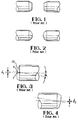
- FIG. 1 a well known prior art system is shown schematically where two ferrules having a chamfered leading edge is provided and where the end face of the ferrule is flat, that is perpendicular to the axial direction.
- the fibres would be located in an aperture along the centerline of the ferrules such that when the two ferrules butt together, the two fibre end faces are also butted one against the other.
- the ferrules are comprised of a ceramic material
- the vertex of the convex surface CS is transferred to a position V as best shown in Figure 3 while the center of the fibre end face remains along the centerline of the ferrule at F.
- Such ferrules and fibres are polished by pressing the ferrule and fibre together against a grinding medium such that the ferrule and fibre are held at an angle relative to the grinding medium, thereby causing the offset angle.
- the problem results in that, when grinding, the high point of the convex surface is located at the vertex. This is due to the fact that the polishing medium "finds" its own center, and that center is the geometric center of the convex surface. Theoretically, if two ferrules could be polished identically, the two would butt together at the centerline of the ferrules.
- the difficulty occurs in that no two ferrules can be polished identically the same, such that in one case a ferrule may be polished as shown in Figure 3, while the next ferrule is polished as shown in Figure 4. It should be noted that the ferrule of Figure 3 is polished further down than that of Figure 4. The more material that is taken off the end face of the ferrule [whilst the curvature (in particular the radius of curvature) is kept constant], the further the vertex of the convex surface formed is offset, such that D1 in Figure 3 is greater than D2 in Figure 4.
- U.S. Patent 5,140,660 to Seiko Giken addresses this common problem, and in an attempt to solve this problem, configures a ferrule with a front cylindrical tip extending forward from the remainder of the body portion of the ferrule.
- the chamfered section is located on the main body portion and the only portion which is ground to a convex surface at an offset angle is the very tip portion. While this system overcomes the problem of the ferrules being mismatched as shown in Figure 5, the portion of the fibre extending forward in the tip of the ferrule is unsupported by the associated alignment sleeve, and could itself lead to fiber misalignment.
- An object of the invention then is to provide an optical fiber system, and more particularly an optical fiber ferrule having a convex surface which is angularly offset from the centerline of the ferrule, but where the vertex of the convex surface is centrally located with the fiber end face.
- a fiber optic ferrule for receiving an optical fiber therein, the ferrule comprising a cylindrical body terminated by a chamfered lead-in edge portion provided with a convex front face which is angularly offset by an acute angle ⁇ with respect to a plane normal to the ferrule longitudinal axis, the ferrule being intended to receive the optical fiber along its longitudinal axis, the ferrule being characterised in that the chamfered lead-in edge portion is asymmetrically shaped, thereby providing different lead-in angles at diametrically opposed longitudinal sides thereof, and disposed such that its intersection with the cylindrical ferrule body is also angularly offset with respect to a plane normal to the ferrule longitudinal axis by substantially the same acute angle ⁇ as that of the convex front face, said asymmetrical lead-in edge portion as well as said angularly offset convex front face being furthermore mutually arranged in a manner such that the distance from the vertex of the convex front
- Embodiments of the invention are defined in the subordinate claims.
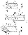
- a fiber ferrule is shown at 2 comprising a fiber 4 where the end of the ferrule has a chamfered lead-in surface 6 and a convex surface 8.
- the convex end face 8 has a radius of curvature of 15mm where the convex surface is offset from the centerline of the fiber ferrule by an angle ⁇ .
- this angle ⁇ typically ranges from 7-15°.
- ⁇ has a value of 9°.
- the asymmetrical chamfer surfaces 26a, 26b define a convex front surface such that, the distances x 1 and x 2 , from the vertex 30 to diametrically opposed points on the outer perimeter of the convex front surface are equal (wherein said outer perimeter is formed by the intersection of said convex front surface with the chamfered lead-in surface 26), while at the same time, maintaining the vertex 30 coincident with the fibre centerline at the convex front face. This remains constant regardless of how much ferrule material is ground from the end face, so long as the offset angle remains the same.
- Figures 7 and 8 show ferrules 22 and 32 respectively having different radii of curvature at the front convex surface, as well as the necessary geometry of the chamfered lead-in edge.
- the ferrules 2, 22 or 32 are comprised of a ceramic material.
- This material could be extruded or moulded into a configuration comprising the cylindrical shape required for the ferrule.
- the chamfered lead-in edge 6 could be formed by grinding, or it could also be produced by other means, for example by initially moulding the lead-in edge into the ceramic ferrule.
- the invention is useable with various radii of curvature of the convex end face, as well as with various offset angles ⁇ ( Figure 6) of the end face. It is further anticipated that the invention is also useable with other ferrule materials such as metal or plastic.
- the above mentioned invention provides for an optical fibre ferrule and a method of producing the same, where a fibre ferrule can include a chamfered lead-in edge, and where the end face of the ferrule can be offset relative to the axial centerline of the fiber ferrule, yet maintain the vertex of the ferrule end face coincident with the centerline of the ferrule and fibre. Also advantageously, this vertex is maintained at the centerline of the ferrule and fibre regardless of the degree of grinding or polishing of the end face. This provides that if the end face of the ferrule or fibre are damaged, the end face of the ferrule can be further polished, removing the damaged material, and yet maintain perfect light transmission qualities with the mating fibre and ferrule.
Landscapes
- Physics & Mathematics (AREA)
- General Physics & Mathematics (AREA)
- Optics & Photonics (AREA)
- Mechanical Coupling Of Light Guides (AREA)
- Grinding And Polishing Of Tertiary Curved Surfaces And Surfaces With Complex Shapes (AREA)
- Optical Couplings Of Light Guides (AREA)
Claims (5)
- Ferrule (2, 22, 32) pour fibre optique destinée à recevoir une fibre optique (4), la ferrule comprenant un corps cylindrique terminé par une portion de bord d'entrée chanfreinée (6) pourvue d'une face avant convexe (8) décalée angulairement d'un angle aigu β par rapport à un plan normal à l'axe longitudinal de la ferrule, la ferrule étant conçue pour recevoir la fibre optique le long de son axe longitudinal, la ferrule étant caractérisée en ce que la portion de bord d'entrée chanfreinée (6) est dotée d'une forme asymétrique, pour offrir ainsi différents angles d'entrée (6a, 6b) au niveau de côtés longitudinaux diamétralement opposés de celle-ci, et disposée de telle sorte que son intersection (7) avec le corps cylindrique de la ferrule soit également décalée angulairement par rapport à un plan normal à l'axe longitudinal de la ferrule d'essentiellement le même angle aigu β que celui de la face avant convexe, ladite portion de bord d'entrée asymétrique (6) ainsi que ladite face avant convexe décalée angulairement (8) étant en outre mutuellement agencées de manière à ce que la distance du sommet (10, 30) de la face avant convexe à un point donné sur le périmètre extérieur de ladite face avant convexe soit identique à celle du sommet à un point diamétralement opposé sur ledit périmètre extérieur, ledit sommet (10, 30) coïncidant avec le point d'intersection de l'axe longitudinal de la ferrule avec la face avant convexe.
- Ferrule pour fibre optique selon la revendication 1, caractérisée en ce que la face avant convexe est une sphéroïde partielle.
- Ensemble de ferrule pour fibre optique comprenant une ferrule selon la revendication 1 ou 2, le long de l'axe longitudinal de laquelle est reçue une fibre optique, dans laquelle le sommet de la face avant convexe coïncide essentiellement avec le point d'intersection de l'axe de la fibre avec la face avant convexe.
- Ensemble de ferrule pour fibre optique selon la revendication 1, 2 ou 3, caractérisé en ce qu'il est incorporé dans un connecteur (14) pour fibres optiques.
- Méthode de formation d'une ferrule pour fibre optique selon l'une quelconque des revendications précédentes, caractérisée par les étapes de:chanfreinage asymétrique d'une portion de bord d'entrée d'un corps cylindrique de la ferrule de telle sorte que l'angle d'entrée au niveau de côtés longitudinaux diamétralement opposés de la portion de bord d'entrée chanfreinée (6) ainsi formée présente différentes valeurs angulaires (6a, 6b) et que l'intersection de ladite portion chanfreinée avec le corps de la ferrule soit décalée angulairement d'un angle aigu β par rapport à un plan normal à l'axe longitudinal de la ferrule, etpolissage ultérieur de la face d'extrémité (8) de la portion de bord d'entrée chanfreinée (6) ainsi formée de façon à la rendre convexe et aussi décalée angulairement par rapport à un plan normal à l'axe longitudinal de la ferrule d'essentiellement le même angle aigu β que celui de l'intersection de la portion chanfreinée avec le corps de la ferrule,dans laquelle ladite portion de bord d'entrée asymétrique (6) ainsi que ladite face avant convexe décalée angulairement (8) sont mutuellement formées de manière à ce que la distance du sommet (10, 30) de la face avant convexe à un point donné sur le périmètre extérieur de ladite face avant convexe soit identique à celle du sommet à un point diamétralement opposé sur ledit périmètre extérieur, ledit sommet (10, 30) coïncidant avec le point d'intersection de l'axe longitudinal de la ferrule avec la face avant convexe.
Applications Claiming Priority (2)
| Application Number | Priority Date | Filing Date | Title |
|---|---|---|---|
| GB9310231 | 1993-05-18 | ||
| GB939310231A GB9310231D0 (en) | 1993-05-18 | 1993-05-18 | Improved fibre optic ferrule |
Publications (2)
| Publication Number | Publication Date |
|---|---|
| EP0625718A1 EP0625718A1 (fr) | 1994-11-23 |
| EP0625718B1 true EP0625718B1 (fr) | 1999-09-01 |
Family
ID=10735693
Family Applications (1)
| Application Number | Title | Priority Date | Filing Date |
|---|---|---|---|
| EP94303420A Expired - Lifetime EP0625718B1 (fr) | 1993-05-18 | 1994-05-12 | Manchon pour fibre optique et méthode pour réaliser un tel manchon |
Country Status (7)
| Country | Link |
|---|---|
| US (1) | US5459806A (fr) |
| EP (1) | EP0625718B1 (fr) |
| JP (1) | JPH06331855A (fr) |
| CN (1) | CN1049737C (fr) |
| CA (1) | CA2121709A1 (fr) |
| DE (1) | DE69420312T2 (fr) |
| GB (1) | GB9310231D0 (fr) |
Families Citing this family (7)
| Publication number | Priority date | Publication date | Assignee | Title |
|---|---|---|---|---|
| US5432880A (en) * | 1994-03-17 | 1995-07-11 | At&T Corp. | Angled optical connector ferrule |
| JPH09145957A (ja) * | 1995-11-20 | 1997-06-06 | Fujitsu Ltd | 光コネクタ |
| JP2857372B2 (ja) * | 1996-06-20 | 1999-02-17 | 有限会社ティー・エム企画 | 光ファイバコネクタ |
| US5734769A (en) * | 1997-01-17 | 1998-03-31 | Adc Telecommunications, Inc. | Optical fiber ferrule |
| US5924234A (en) * | 1997-11-20 | 1999-07-20 | Trijicon, Inc. | Optical sighting device |
| US6579015B2 (en) * | 2001-02-01 | 2003-06-17 | Fitel Usa Corporation | Optical connector ferrule having a multiple-angled pedestal |
| US6807742B2 (en) * | 2002-09-06 | 2004-10-26 | Trijicon, Inc. | Reflex sight with multiple power sources for reticle |
Family Cites Families (7)
| Publication number | Priority date | Publication date | Assignee | Title |
|---|---|---|---|---|
| US4978193A (en) * | 1989-08-24 | 1990-12-18 | Raychem Corporation | Optical fiber connector which provides a high signal return loss |
| CH678980A5 (fr) * | 1989-10-02 | 1991-11-29 | Diamond Sa | |
| JPH03210509A (ja) * | 1990-01-12 | 1991-09-13 | Seiko Giken:Kk | 光コネクタフェルール部材 |
| DE4020528A1 (de) * | 1990-06-28 | 1992-01-02 | Philips Patentverwaltung | Optische verbindung der enden zweier koaxialer lichtwellenleiter |
| JP2633073B2 (ja) * | 1990-09-07 | 1997-07-23 | 株式会社精工技研 | 可変型光減衰器 |
| JP3304992B2 (ja) * | 1991-07-05 | 2002-07-22 | 株式会社精工技研 | 光結合器 |
| JP3116124B2 (ja) * | 1991-08-23 | 2000-12-11 | 東京特殊電線株式会社 | 光ファイバ接続体 |
-
1993
- 1993-05-18 GB GB939310231A patent/GB9310231D0/en active Pending
-
1994
- 1994-04-15 US US08/229,477 patent/US5459806A/en not_active Expired - Fee Related
- 1994-04-20 CA CA002121709A patent/CA2121709A1/fr not_active Abandoned
- 1994-05-12 EP EP94303420A patent/EP0625718B1/fr not_active Expired - Lifetime
- 1994-05-12 DE DE69420312T patent/DE69420312T2/de not_active Expired - Fee Related
- 1994-05-17 CN CN94105546.9A patent/CN1049737C/zh not_active Expired - Fee Related
- 1994-05-18 JP JP6128152A patent/JPH06331855A/ja active Pending
Also Published As
| Publication number | Publication date |
|---|---|
| GB9310231D0 (en) | 1993-06-30 |
| DE69420312D1 (de) | 1999-10-07 |
| CN1109175A (zh) | 1995-09-27 |
| US5459806A (en) | 1995-10-17 |
| CA2121709A1 (fr) | 1994-11-19 |
| CN1049737C (zh) | 2000-02-23 |
| JPH06331855A (ja) | 1994-12-02 |
| EP0625718A1 (fr) | 1994-11-23 |
| DE69420312T2 (de) | 2000-04-13 |
Similar Documents
| Publication | Publication Date | Title |
|---|---|---|
| US6550979B1 (en) | Floating connector subassembly and connector including same | |
| EP0419699B1 (fr) | Méthode de fabrication d'un connecteur à fibre optique | |
| US4615581A (en) | Optical fiber connector | |
| JP3650109B2 (ja) | 光ファイバのフェルールの研磨法 | |
| CA2068453C (fr) | Fiche de connecteur optique multifibre a indice de reflexion et d'affaiblissement d'insertion peu eleve | |
| US4705352A (en) | Fiber optic connector | |
| US5390269A (en) | Fiber optic connector with high resolution tunable fiber holder | |
| EP2270561B1 (fr) | Connecteur de fibres optiques à faisceau étendu avec morçeau de fibre et lentille et procédé de fabrication | |
| US4834494A (en) | Expanded beam waveguide connector | |
| US4787701A (en) | Optical fiber contact assembly | |
| JPH07276207A (ja) | 光ファイバコネクタのフェルールの端面の形成方法 | |
| US4383732A (en) | Fiber optic connector | |
| EP0625718B1 (fr) | Manchon pour fibre optique et méthode pour réaliser un tel manchon | |
| US6872008B2 (en) | Conversion sleeve and optical adapter | |
| EP0911661B1 (fr) | Ferrule pour connecteur de fibres optiques | |
| US4955976A (en) | Optical fiber connector | |
| US5687269A (en) | Optical connector and polishing method of its end surface | |
| US4856866A (en) | Optical fiber connecting means | |
| EP0264976B1 (fr) | Bout et méthode pour terminer une membre de transmission fibre-optique | |
| EP0056192A1 (fr) | Connexion à fibre optique, procédé de fabrication de la connexion et câble à fibre optique pour utilisation dans la connexion | |
| JPS61132911A (ja) | 光コネクタプラグ | |
| EP1335221B1 (fr) | Ferrule pour connecteur optique dont l'extrêmité comprend plusieurs biseaux | |
| US20020102067A1 (en) | Optical connector ferrule having a multiple-angled pedestal | |
| JP2003241021A (ja) | 光ファイバモジュール | |
| JPH07318757A (ja) | 光コネクタおよびその接続方法 |
Legal Events
| Date | Code | Title | Description |
|---|---|---|---|
| PUAI | Public reference made under article 153(3) epc to a published international application that has entered the european phase |
Free format text: ORIGINAL CODE: 0009012 |
|
| AK | Designated contracting states |
Kind code of ref document: A1 Designated state(s): CH DE FR GB IT LI |
|
| 17P | Request for examination filed |
Effective date: 19950522 |
|
| R17P | Request for examination filed (corrected) |
Effective date: 19950522 |
|
| 17Q | First examination report despatched |
Effective date: 19980618 |
|
| GRAG | Despatch of communication of intention to grant |
Free format text: ORIGINAL CODE: EPIDOS AGRA |
|
| GRAG | Despatch of communication of intention to grant |
Free format text: ORIGINAL CODE: EPIDOS AGRA |
|
| GRAH | Despatch of communication of intention to grant a patent |
Free format text: ORIGINAL CODE: EPIDOS IGRA |
|
| GRAH | Despatch of communication of intention to grant a patent |
Free format text: ORIGINAL CODE: EPIDOS IGRA |
|
| GRAA | (expected) grant |
Free format text: ORIGINAL CODE: 0009210 |
|
| RBV | Designated contracting states (corrected) |
Designated state(s): CH DE FR GB IT LI |
|
| AK | Designated contracting states |
Kind code of ref document: B1 Designated state(s): CH DE FR GB IT LI |
|
| REG | Reference to a national code |
Ref country code: CH Ref legal event code: EP |
|
| REF | Corresponds to: |
Ref document number: 69420312 Country of ref document: DE Date of ref document: 19991007 |
|
| ITF | It: translation for a ep patent filed | ||
| ET | Fr: translation filed | ||
| PLBE | No opposition filed within time limit |
Free format text: ORIGINAL CODE: 0009261 |
|
| STAA | Information on the status of an ep patent application or granted ep patent |
Free format text: STATUS: NO OPPOSITION FILED WITHIN TIME LIMIT |
|
| 26N | No opposition filed | ||
| REG | Reference to a national code |
Ref country code: GB Ref legal event code: IF02 |
|
| PGFP | Annual fee paid to national office [announced via postgrant information from national office to epo] |
Ref country code: GB Payment date: 20020404 Year of fee payment: 9 |
|
| PGFP | Annual fee paid to national office [announced via postgrant information from national office to epo] |
Ref country code: FR Payment date: 20020503 Year of fee payment: 9 |
|
| PGFP | Annual fee paid to national office [announced via postgrant information from national office to epo] |
Ref country code: DE Payment date: 20020531 Year of fee payment: 9 |
|
| PGFP | Annual fee paid to national office [announced via postgrant information from national office to epo] |
Ref country code: CH Payment date: 20020618 Year of fee payment: 9 |
|
| PG25 | Lapsed in a contracting state [announced via postgrant information from national office to epo] |
Ref country code: GB Free format text: LAPSE BECAUSE OF NON-PAYMENT OF DUE FEES Effective date: 20030512 |
|
| PG25 | Lapsed in a contracting state [announced via postgrant information from national office to epo] |
Ref country code: LI Free format text: LAPSE BECAUSE OF NON-PAYMENT OF DUE FEES Effective date: 20030531 Ref country code: CH Free format text: LAPSE BECAUSE OF NON-PAYMENT OF DUE FEES Effective date: 20030531 |
|
| PG25 | Lapsed in a contracting state [announced via postgrant information from national office to epo] |
Ref country code: DE Free format text: LAPSE BECAUSE OF NON-PAYMENT OF DUE FEES Effective date: 20031202 |
|
| GBPC | Gb: european patent ceased through non-payment of renewal fee |
Effective date: 20030512 |
|
| REG | Reference to a national code |
Ref country code: CH Ref legal event code: PL |
|
| PG25 | Lapsed in a contracting state [announced via postgrant information from national office to epo] |
Ref country code: FR Free format text: LAPSE BECAUSE OF NON-PAYMENT OF DUE FEES Effective date: 20040130 |
|
| REG | Reference to a national code |
Ref country code: FR Ref legal event code: ST |
|
| PG25 | Lapsed in a contracting state [announced via postgrant information from national office to epo] |
Ref country code: IT Free format text: LAPSE BECAUSE OF NON-PAYMENT OF DUE FEES;WARNING: LAPSES OF ITALIAN PATENTS WITH EFFECTIVE DATE BEFORE 2007 MAY HAVE OCCURRED AT ANY TIME BEFORE 2007. THE CORRECT EFFECTIVE DATE MAY BE DIFFERENT FROM THE ONE RECORDED. Effective date: 20050512 |