EP0625740B1 - Système amplificateur pour soupape proportionnelle commandeé par solénoide - Google Patents
Système amplificateur pour soupape proportionnelle commandeé par solénoide Download PDFInfo
- Publication number
- EP0625740B1 EP0625740B1 EP94105998A EP94105998A EP0625740B1 EP 0625740 B1 EP0625740 B1 EP 0625740B1 EP 94105998 A EP94105998 A EP 94105998A EP 94105998 A EP94105998 A EP 94105998A EP 0625740 B1 EP0625740 B1 EP 0625740B1
- Authority
- EP
- European Patent Office
- Prior art keywords
- input
- switch
- signal
- input operating
- solenoid controlled
- Prior art date
- Legal status (The legal status is an assumption and is not a legal conclusion. Google has not performed a legal analysis and makes no representation as to the accuracy of the status listed.)
- Expired - Lifetime
Links
- 238000003745 diagnosis Methods 0.000 claims description 12
- 230000004044 response Effects 0.000 claims description 10
- 238000000034 method Methods 0.000 description 14
- 230000006870 function Effects 0.000 description 8
- 230000008569 process Effects 0.000 description 6
- 230000007246 mechanism Effects 0.000 description 5
- 230000000994 depressogenic effect Effects 0.000 description 4
- 101001128814 Pandinus imperator Pandinin-1 Proteins 0.000 description 3
- 101001024685 Pandinus imperator Pandinin-2 Proteins 0.000 description 3
- 238000010586 diagram Methods 0.000 description 3
- 238000006073 displacement reaction Methods 0.000 description 3
- 206010044565 Tremor Diseases 0.000 description 2
- 238000010276 construction Methods 0.000 description 2
- 230000002159 abnormal effect Effects 0.000 description 1
- 230000004075 alteration Effects 0.000 description 1
- 230000008901 benefit Effects 0.000 description 1
- 230000008859 change Effects 0.000 description 1
- 230000007423 decrease Effects 0.000 description 1
- 230000000881 depressing effect Effects 0.000 description 1
- 238000013461 design Methods 0.000 description 1
- 238000012986 modification Methods 0.000 description 1
- 230000004048 modification Effects 0.000 description 1
- 230000007935 neutral effect Effects 0.000 description 1
- 238000012545 processing Methods 0.000 description 1
- 230000009993 protective function Effects 0.000 description 1
- 230000009979 protective mechanism Effects 0.000 description 1
- 230000009467 reduction Effects 0.000 description 1
- 238000012360 testing method Methods 0.000 description 1
Images


Classifications
-
- G—PHYSICS
- G05—CONTROLLING; REGULATING
- G05D—SYSTEMS FOR CONTROLLING OR REGULATING NON-ELECTRIC VARIABLES
- G05D16/00—Control of fluid pressure
- G05D16/20—Control of fluid pressure characterised by the use of electric means
- G05D16/2006—Control of fluid pressure characterised by the use of electric means with direct action of electric energy on controlling means
- G05D16/2013—Control of fluid pressure characterised by the use of electric means with direct action of electric energy on controlling means using throttling means as controlling means
-
- Y—GENERAL TAGGING OF NEW TECHNOLOGICAL DEVELOPMENTS; GENERAL TAGGING OF CROSS-SECTIONAL TECHNOLOGIES SPANNING OVER SEVERAL SECTIONS OF THE IPC; TECHNICAL SUBJECTS COVERED BY FORMER USPC CROSS-REFERENCE ART COLLECTIONS [XRACs] AND DIGESTS
- Y10—TECHNICAL SUBJECTS COVERED BY FORMER USPC
- Y10T—TECHNICAL SUBJECTS COVERED BY FORMER US CLASSIFICATION
- Y10T137/00—Fluid handling
- Y10T137/8593—Systems
- Y10T137/86389—Programmer or timer
Definitions
- the present invention generally relates to an amplifying system for solenoid controlled proportion valve used in a hydraulic system, and more particularly to an intelligent amplifying system having a fault diagnosis function and a protective function in the hydraulic system.
- an intelligent amplifying system having a fault diagnosis function and a protective function in the hydraulic system.
- Fig. 1 shows a schematic view of a mechanism for controlling a conventional solenoid controlled proportion valve, in which an amplifying circuit 1 for the solenoid controlled proportion valve(hereinafter, referred to as "proportion valve")controls an operation of the proportion valve in response to operating signals provided from operating members such as an electric joystick 2, an electric pedal 3, and an external controller 4 having a function similar to those of the members 2 and 3.
- an amplifying circuit 1 for the solenoid controlled proportion valve hereinafter, referred to as "proportion valve”
- a spool(not shown)in the proportion valve 5 moves in response to the transmitted amount of an electric current. Accordingly, an oil pressure(or a flow amount)can be controlled by a displacement of the spool.
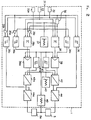
- Fig. 2 illustrates a conventional analog amplifying circuit.
- the operating signal provided from operating members(see reference numerals 2, 3 and 4 shown in Fig. 1) is transmitted to the amplifying circuit 1 through an input terminal 31.
- the input signal is then transmitted to four limiters 36, 36a, 36b and 36c composed of Schmidt trigger circuit, respectively.
- the first trip point setting unit 32 determines the lower trip point which corresponds to 10% of the input signal amplitude.
- the limiters 36 and 36b operated by the first trip point setting unit 32 and inverters 35a, 35b, 35c put the first proportion valve 5 into an enable state and the second proportion valve 5a into a disable state when the input signal is above the first lower trip point.
- limiters 36 and 36b for example in hydraulic equipments, is accomplished in such a way that in its forward move the first proportion valve is put to enable state with the second proportion valve put to disable state, and in its backward move each valve is put to the opposite state, respectively.
- the upper trip point corresponding to 90% of the input signal is determined by the second trip point setting unit 32a.
- the range limiters 36a and 36c allow a maximum amount of current(I limit)to be transmitted to the proportion valves 5 and 5a as shown in Fig. 3 which represents input/output characteristic graph of amplifying circuit 1.
- An offset current(I offset) shown in Fig. 3 is set by an offset setting unit 33, and an amplitude of the offset current(I offset) can be controlled by a variable resistor(not shown).
- the input signal provided from the operating means through the input terminal 31 to the amplifying circuit 1 is transmitted to two adders 38 and 38a after the input signal has been controlled to take a predetermined gain determined by a gain adjusting member 34.
- a dither generator 37 is employed to make use of the principle that it is easier to move the moving body than to move the fixed body.
- the dither generator 37 generates a dither signal for enhancement of mechanical response characteristics by trembling each spool of the proportion valves 5 and 5a with a very small displacement.
- the dither signal is a voltage signal of a triangular wave having a predetermined frequency and amplitude.
- the adders 38 and 38a add the offset signal to the output and dither signals of the gain adjusting member 34 while the adder 38a receives an inversion output of the gain adjusting members 34 through an inverter 35, 35a, 35b and 35c.
- An output signal controllers 39 and 39a are operated in such a manner that the ratio of output signal to input signal in the amplifying circuit 1 is kept constant based on a signal provided from a current sensor 40 which detects a current amount supplied to the proportion valves 5 and 5a.
- Pulse width modulators 42 and 42a compare the output signals of controllers 39 and 39a with those of current limiters 41 and 41a which prevent an overcurrent from flowing and that of a carrier generator 43 generating a triangular wave, and then, from the above comparison, generate a pulse width modulation wave of a variable duty.
- Current supplying units 44 and 44a can be subject to ON state or OFF state depending on the output of the pulse width modulators 42 and 42a, so that the amount supplied from a power supply(not shown) to the proportion valves 5 and 5a can be controlled.
- the operation of the proportion valves 5 and 5a are controlled by the current amount supplied by way of the current supplying units 44 and 44a.
- variable resistors included in the offset setting portion 33, the gain controller 34 and the dither generator 37 respectively should be adjusted one by one by a trial and error method.
- the conventional system is not provided with a failure diagnosis function which is capable of managing effectively the accidents when the system errors occur.
- the primary object of the present invention is to provide an amplifying system having a microprocessor to make it possible to adjust parameters easily with a simple circuit design.
- Another object of the present invention is to provide an intelligent amplifying system to control the valve operation, making it possible to perform automatically a simple repeating work without any manual operation.
- Still another object of the present invention is to provide an amplifying system having a safety mechanism by which system errors can be prevented.
- Still another object of the present invention is to provide an amplifying system capable of increasing an efficiency of equipment with a self-failure diagnosis function.
- an amplifying system for controlling an operation of at least one solenoid controlled proportion valve, as defined in claim 1.
- the system further comprises a switch for indicating a start and a stop of a work; and a means for allowing the work to be initiated by controlling the operation of the solenoid controlled proportion valve in response to the input operational signal provided from the input operating means when the switch is ON state, and the work not to be initiated regardless of the input operational signals provided from the input operating means when the switch is not ON state.
- the present system further comprises a switch for indicating a start a stop of a work; and a means for stopping the operation of the solenoid controlled proportion valve automatically when the input operating siganl is not fed from the input operating means any more in a predetermined period from ON state of the switch.
- the present invention further comprises a memory means for storing the predetermined parameters; and a means for changing the parameters in the memory means.
- the present invention further comprises a switch controlling the automatic operation; a memory means for storing all data to control the solenoid controlled proportion valve when the switch is pushed for the first time; and a means for reading out the data from the memory means when the switch is pushed for the second time.
- the present invention further comprises a means for sensing a current amount provided to the solenoid controlled proportion valve; and a failure diagnosis means for detecting whether or not a trouble occurs by the current amount sensed from the sensing means.
- Fig. 1 illustrates a schematic block diagram of a mechanism for operating a solenoid controlled proportion valve.
- Fig. 2 illustrates a circuit diagram of a conventional analog amplifying circuit.
- Fig. 3 illustrates a characteristic view of input/output signals of an amplifier circuit for a valve control.
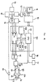
- Fig. 4 illustrates a hardware construction view of an intelligent amplifier system according to the present invention.
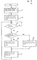
- Fig. 5A illustrates a flow chart of a dither routine for generating a dither signal by a microcomputer.
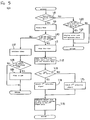
- Fig. 5B illustrates a flow chart explaining a sequential process being performed by the microcomputer.
- Fig. 5C illustrates a flow chart of a failure diagnosis routine in the system.
- Fig. 4 shows an embodiment of the amplifier system employing the microcomputer according to the present invention, which is used to control two proportion valves
- Fig. 5 shows a flow chart explaining its execution process.
- the microcomputer 100 includes a central processing unit(CPU) 101 for performing various operation functions and control functions, an interrupt control unit 102, a memory 103 having a random access memory(RAM) and a read only memory(ROM), and an input/output processor 104.
- CPU central processing unit
- interrupt control unit 102 for performing various operation functions and control functions
- memory 103 having a random access memory(RAM) and a read only memory(ROM)
- input/output processor 104 input/output processor
- FIG. 4 an interface 110 for connecting the microcomputer 100 to an external personal computer(PC) 111, a start/stop switch 112 for controlling the equipment, and an automatic operation switch 113 for indicating the automatic repeating operation are shown.
- A/D converter analog to digital converter
- the start/stop switch 112 and the automatic operation switch 113 are also connected to other input ports of the input/output processor through the A/D converter 114.
- a reference numeral 115 designates a parallel to serial(PS) converter connected to output ports of the input/output processor 104 and 116, and 117 designate an alarm and a display controlled by CPU 101 of the microcomputer 100, respectively.
- a signal changing unit 118 for changing a signal path of a serial digital signal provided from the PS converter 115 controlled by the CPU 101 comprises a multiplexer.
- reference numerals 119 and 120 of which the output terminals are connected to control terminals of power transistors within electrical current supplying units 44 and 44a designate OR logic gates for logic operation of the outputs of the PS converter 115 and the signal changing unit 118.
- Fig. 5A represents the flow diagram for the execution process of the dither signal generating means which is the first functioning means performed by microcomputer 100.
- the dither signal generator comprises a CPU 101 and a memory 103.
- the dither signal generator reads from ROM of the memory 103 a frequency, amplitude, offset and gain data of the dither which have been preset, designates a specified area within RAM of the memory 103 to form the dither signal, and stores the read-in data in the said specified area(step S1)(for example, designate variable DITH_VALUE in the OFF address of RAM).
- step S2 an initial value of dither data and the number of interrupts per cycle of the dither signal to be formed are counted.
- the initial value of the dither is set to -1V and 20 interrupts are generated in one cycle since the period of the cycle of the dither signal to be formed is set to 20 msec.
- the dither signal generating means detects whether or not the interrupt is generated from the interrupt controller 102(step S3)
- step S3 If the interrupt has been generated in step S3, it is detected whether or not the generated interrupt is such that the number of interrupts are a half or less than the generation number per cycle(for example, 10 interrupts or less in case of 20 times per period)(step S4).
- a predetermined addend is added to the dither value(step S5). This addend is determined by the generation numbers of interrupt per cycle or the dither signal to be formed and a peak value(i.e., two times the amplitude value).
- the addend value is 200 mV.
- the dither data is -1V + 200 mV
- the dither data value changes to -1V + 400 mV.
- the dither value is 1V.
- a predetermined substrahend is subtracted from the dither value(step S6).
- This subtrahend is the same value as the addend described above. For example, when the 11th interrupt of a first period is generated, the dither value is 1V - 200 mV, and when the last interrupt(i.e., 20th interrupt) is generated, the dither value is -1V.
- the dither signal of a triangular wave can be formed.
- the dither value is determined in response to the interrupt generation as mentioned above, it is added to an offset value in order to obtain a constant offset current(step S7).
- the dither data provided from the dither generating means whenever the interrupt is generated are recorded in a register(not shown) which corresponds to an output port Pout1 of the input/output processor 104, and then fed to the PS converter 115.
- a parallel dither data which are produced from the input/output processor 104 are converted to serial data by the PS converter 115, and provided to two OR gates 119 and 120.
- a means for controlling current to the proportion valves 5 and 5a in response to the input operation signal which is fed from the electric joystick 2, the electric pedal 3 and the external controller 4 has hardware construction as a shown in Fig. 4.
- the joystick 2 and the pedal 3 for sending out the analog signal are connected to an input port of the A/D converter 114 coupled to the input/output processor 104 of microcomputer 100, and the external controller 4 for sending out the digital signal is connected directly to the input port of the input/output processor 104.
- the A/D converter 114 may be placed within the input/output processor 104 of the microcomputer 100.
- the input/output processor 104 receives data from the external through input port Pin1 and Pin2 depending on the instruction of the CPU 101, or sends out the data provided from the CPU 101 or the memory 103 to the external through output ports Pout1 and Pout2.
- the CPU 101 Whenever the interrupt is generated by the interrupt controller 102, the CPU 101 makes commands so that the input/output processor 104 receives the data.
- the CPU 101 receives the data from the input ports Pin1 and Pin2 of the input/output processor 104, and, in response to the received data, controls the proportion valves 5 and 5a, as shown in the flowchart of Fig.5B.
- CPU 101 executes the control to generate the pulse of a variable duty corresponding to the input data. Whether or not the operator of the hydraulic equipment is willing to run the equipment is transferred to microcomputer 100 by operation indicating switch 112.
- the CPU 101 sets a flag within RAM to "H(high)” state, and when the switch 112 is pushed again to stop the equipment, the flag turns to "L(low)” state. Accordingly, pushing the switch 112 turns the start flag to "High(logically 1)"(step S9).
- a predetermined value is set in a timer, and its value increases or decreases in step S9, the input data is received every time the interrupt is generated when the timer reaches a predetermined value or 0, and the operation of the input data is performed.
- step S11 the operation of the timer is stopped(step S11), and a predetermined operation is performed by reading the data from the input port, where a variable duty for generating the output current is calculated corresponding to the value of the gain value times the input data provided from the operating means 2 and 3 and the external controller 4(step S12).
- step S13 it is determined whether or not the input data is for controlling the operation of the first valve 5. If the said input data is for the operation of the first valve, a selection signal in the first level(or logical "1") is fed to a selection port b of the path router 118, allowing ports a and b to be electrically connected to each other.
- a selection signal in the second level(or, logically "0") is fed to a selection port C of the path router 118, allowing the ports a and c to be connected to each other.
- a number of the selection signals provided from the CPU 101 to the path router 118 may be varied depending on the number of valves.
- step S16 the data resulting from the final operation of the input data are given as the output data to a register(not shown) within the input/output processor 104 which corresponds to the output port Pout2.
- the PS converter 115 converts the received parallel data to the serial data and sends it to the changer 118.
- the pulses provided from the PS converter 115 are fed to OR gate 119 through the path router 118 which is being controlled by the selection signal in the first level.
- the pulses are fed to OR gate 120.
- step S17 if the data to be read from the input port is not present when the start flag is in "HIGH” state(i.e., "NO” in step S10), the operation of the internal timer is initiated (step S17).
- the start flag becomes "LOW" state(step S19).
- steps S17 to S19 can be utilized to stop automatically the equipment if the operator leaves from his place without depressing the start/stop switch 112 during operation, whereby the equipment is stopped temporarily.
- the present invention is provided with a protective mechanism for controlling the equipment through the microcomputer 100 according to the ON/OFF state of the start/stop switch, preventing trembles due to the errorneous operation and unexpected accidents.
- An external power supply(not shown) for supplying a bias voltage to the electric joystick 2, the electric pedal 3, and the input elements 2, 3 and 4 are designed in such a way that when these elements are in trouble, the output at the failure time exceeds the preset input range.
- a bias voltage of D.C. 20 Volts is applied to the joystick or the pedal 3.
- the input voltage shown in the characteristic curve of Fig. 3 is 100 %
- its output is D.C. 20 volts
- D.C. 10 volts When it is in neutral position, its output is D.C. 15 volts.
- the microcomputer 100 receives an abnormal signal from the input means 2 and 3, etc., and the failure diagnosis means being controlled by the microcomputer 100 indicates the failure through the alarm unit 116 and the display unit 117.
- the failure diagnosis means indicates the failure through the alarm unit 116 and the display unit 117 since it is assumed that the proportion valves 5 and 5a or the current sensor are in trouble(step S22 ⁇ S25).
- the failure diagnosis means not only displays its test results, but indicates when the power voltage provided to the means exceeds the allowable range.
- the data set can be determined by the following three ways.
- a start information for this operation is provided to the microcomputer 100 through an automatic operating switch 113.
- the microcomputer 100 stores all the processes in RAM of the memory 103 until the switch 113 is depressed again. If the operation amount exceeds a capacity of the memory 103, the alarm unit 116 is operated and such situation is displayed in the display unit 117.
- microcomputer 100 controls the operation of valves 5, 5a by reading out successively the operation processes recorded in the memory 103.
- an intelligent amplifying system using a microcomputer which has the advantage that the size and weight of system hardware can be greatly reduced compared with those of the conventional analog amplifying system.
- the failure diagnosis of the system is provided, so that the working efficiency of the equipment can be increased.
Landscapes
- Physics & Mathematics (AREA)
- Fluid Mechanics (AREA)
- General Physics & Mathematics (AREA)
- Engineering & Computer Science (AREA)
- Automation & Control Theory (AREA)
- Feedback Control In General (AREA)
- Safety Devices In Control Systems (AREA)
- Magnetically Actuated Valves (AREA)
- Flow Control (AREA)
Claims (4)
- Système d'amplification intelligent comprenant un micro-ordinateur (100) pour l'ajustement automatique de paramètres en vue de commander le fonctionnement de deux soupapes à électro-aimant à action proportionnelle commandée (5, 5a) en délivrant un signal de commande en réponse à un signal de fonctionnement d'entrée délivré à partir de moyens de fonctionnement d'entrée (2, 3, 4) sur des bornes de commande respectives de deux moyens d'alimentation en courant (44,44a) connectés aux soupapes à électro-aimant à action proportionnelle commandée, comportant :un moyen (101, 102, 103) pour générer des signaux de tremblement d'une onde triangulaire ayant une fréquence et une amplitude prédéterminées selon les paramètres prédéterminés par le micro-ordinateur (100) ;un moyen (104) pour générer des signaux impulsionnels d'un cycle variable ayant un gain prédéterminé en réponse au signal de fonctionnement d'entrée délivré à partir du moyen de fonctionnement d'entrée (2, 3, 4) ;deux moyens logiques OU (119, 120) comportant une première borne d'entrée destinée à recevoir les signaux de tremblement, une seconde borne d'entrée destinée à recevoir les signaux impulsionnels et une borne de sortie reliée à la borne de commande d'un moyen d'alimentation en courant respectif ;un moyen (101) pour générer un signal de sélection basé sur le signal de fonctionnement d'entrée en vue de sélectionner le fonctionnement de l'une ou l'autre des soupapes (5, 5a) ; etun moyen (118) pour modifier le trajet de sortie des signaux impulsionnels délivrés à partir du moyen générateur d'impulsions (104) sur la seconde borne d'entrée du moyen logique OU (119, 120) en étant commandé par le signal de sélection,un moyen de mémoire (103) pour mémoriser les paramètres prédéterminés ; etun moyen (100) pour modifier les paramètres présents dans le moyen de mémoire,un interrupteur (113) commandant le fonctionnement automatique ;le moyen de mémoire (103) mémorisant toutes les données en vue de commander la soupape à électro-aimant à action proportionnelle commandée lorsque l'interrupteur est poussé pour la première fois ; etun moyen pour extraire les données du moyen de mémoire lorsque l'interrupteur est poussé pour la seconde fois,un moyen (40) pour détecter une intensité de courant délivré à la soupape à électro-aimant à action proportionnelle commandée ;un moyen de diagnostic de défaillance qui est commandé par le micro-ordinateur (100) pour détecter s'il se produit ou non une anomalie d'aprés l'intensité du courant détectée par le moyen de détection ;un moyen (116) pour générer un signal d'alarme lorsque l'apparition de l'anomalie est détectée par le moyen de diagnostic de défaillance ; etun moyen (117) pour afficher la situation lorsque se produit l'anomalie, dans lequel le micro-ordinateur (100) est connecté à un ordinateur personnel externe (111) par une interface (110).
- Système d'amplification selon la revendication 1, comportant en outre :un interrupteur (112) pour indiquer un commencement et un arrêt d'un travail ; etun moyen pour permettre que le travail soit initié en commandant le fonctionnement de la soupape à électro-aimant à action proportionnelle commandée en réponse au signal de fonctionnement d'entrée délivré à partir du moyen d'actionnement d'entrée lorsque l'interrupteur se trouve à l'état fermé, et que le travail ne soit pas initié, sans tenir compte des signaux de fonctionnement d'entrée délivrés à partir du moyen de fonctionnement d'entrée, lorsque l'interrupteur n'est pas à l'état fermé.
- Système d'amplification selon la revendication 1, comportant en outre :un interrupteur (112) pour indiquer un commencement et un arrêt d'un travail ; etun moyen pour arrêter automatiquement le fonctionnement de la soupape à électro-aimant à action proportionnelle commandée lorsque le signal de fonctionnement d'entrée cesse d'être envoyé à partir du moyen de fonctionnement d'entrée pendant une durée prédéterminée partant de l'état de fermeture (ON) de l'interrupteur.
- Système d'amplification intelligent selon la revendication 2, comprenant en outre :
un moyen pour arrêter automatiquement le fonctionnement de la soupape à électro-aimant à action proportionnelle commandée lorsque le signal de fonctionnement d'entrée cesse d'être délivré à partir du moyen de fonctionnement d'entrée pendant une période prédéterminée partant de l'état de fermeture (ON) de l'interrupteur (112).
Applications Claiming Priority (2)
| Application Number | Priority Date | Filing Date | Title |
|---|---|---|---|
| KR9306456 | 1993-04-16 | ||
| KR1019930006456A KR950013136B1 (ko) | 1993-04-16 | 1993-04-16 | 전자비례밸브용 증폭장치 |
Publications (3)
| Publication Number | Publication Date |
|---|---|
| EP0625740A2 EP0625740A2 (fr) | 1994-11-23 |
| EP0625740A3 EP0625740A3 (fr) | 1995-02-01 |
| EP0625740B1 true EP0625740B1 (fr) | 1997-08-06 |
Family
ID=19354092
Family Applications (1)
| Application Number | Title | Priority Date | Filing Date |
|---|---|---|---|
| EP94105998A Expired - Lifetime EP0625740B1 (fr) | 1993-04-16 | 1994-04-18 | Système amplificateur pour soupape proportionnelle commandeé par solénoide |
Country Status (5)
| Country | Link |
|---|---|
| US (1) | US5638863A (fr) |
| EP (1) | EP0625740B1 (fr) |
| JP (1) | JPH0712263A (fr) |
| KR (1) | KR950013136B1 (fr) |
| DE (1) | DE69404754D1 (fr) |
Families Citing this family (8)
| Publication number | Priority date | Publication date | Assignee | Title |
|---|---|---|---|---|
| US6202980B1 (en) | 1999-01-15 | 2001-03-20 | Masco Corporation Of Indiana | Electronic faucet |
| US6457088B1 (en) | 1999-07-20 | 2002-09-24 | Vickers, Inc. | Method and apparatus for programming an amplifier |
| US6736094B2 (en) * | 2002-06-17 | 2004-05-18 | Borgwarner Inc. | VCT solenoid dither frequency control |
| JP3814277B2 (ja) * | 2004-03-31 | 2006-08-23 | 株式会社コガネイ | 比例電磁弁の制御装置 |
| US20080099705A1 (en) * | 2006-10-25 | 2008-05-01 | Enfield Technologies, Llc | Retaining element for a mechanical component |
| US20090319088A1 (en) * | 2008-06-18 | 2009-12-24 | Richard Reed | Methods and apparatus for controlling operation of a control device |
| US9362710B1 (en) * | 2015-07-01 | 2016-06-07 | Northrop Grumman Systems Corporation | Multichannel controller |
| US11879871B2 (en) | 2018-11-30 | 2024-01-23 | Illinois Tool Works Inc. | Safety systems requiring intentional function activation and material testing systems including safety systems requiring intentional function activation |
Family Cites Families (7)
| Publication number | Priority date | Publication date | Assignee | Title |
|---|---|---|---|---|
| GB1532989A (en) * | 1974-11-06 | 1978-11-22 | Nissan Motor | Method of and device for controlling solenoid operated flow control means |
| JPS5869522A (ja) * | 1981-10-22 | 1983-04-25 | オリンパス光学工業株式会社 | 内視鏡装置 |
| JPS58144918A (ja) * | 1982-02-24 | 1983-08-29 | Hitachi Ltd | 配水管網の圧力・流量制御方式 |
| DE3506849C1 (de) * | 1985-02-27 | 1986-06-26 | Zahnräderfabrik Renk AG, 8900 Augsburg | Elektrische Steuerschaltung |
| DE3717260A1 (de) * | 1987-05-22 | 1988-12-01 | Rexroth Mannesmann Gmbh | Schaltungsanordnung zum uebertragen einer versorgungsspannung und eines steuersignals |
| US5172311A (en) * | 1988-11-11 | 1992-12-15 | Mannesmann Rexroth Gmbh | Electrical amplifier for controlling valves |
| GB9111544D0 (en) * | 1991-05-29 | 1991-07-17 | Romatic Ltd | A speed control unit |
-
1993
- 1993-04-16 KR KR1019930006456A patent/KR950013136B1/ko not_active Expired - Fee Related
-
1994
- 1994-01-28 JP JP6026182A patent/JPH0712263A/ja active Pending
- 1994-04-18 EP EP94105998A patent/EP0625740B1/fr not_active Expired - Lifetime
- 1994-04-18 DE DE69404754T patent/DE69404754D1/de not_active Expired - Fee Related
- 1994-04-18 US US08/228,743 patent/US5638863A/en not_active Expired - Fee Related
Also Published As
| Publication number | Publication date |
|---|---|
| EP0625740A3 (fr) | 1995-02-01 |
| DE69404754D1 (de) | 1997-09-11 |
| EP0625740A2 (fr) | 1994-11-23 |
| JPH0712263A (ja) | 1995-01-17 |
| US5638863A (en) | 1997-06-17 |
| KR950013136B1 (ko) | 1995-10-25 |
Similar Documents
| Publication | Publication Date | Title |
|---|---|---|
| US6512960B1 (en) | Positioner and method for operating the positioner | |
| EP0625740B1 (fr) | Système amplificateur pour soupape proportionnelle commandeé par solénoide | |
| US5214362A (en) | Method for detecting a collision and stopping drive of a machine driven by servomotors | |
| GB2118737A (en) | Machine process controller | |
| GB1564073A (en) | Electrohydraulic governor employing duplex digital controller system | |
| EP0088364A1 (fr) | Dispositif de sécurité pour circuit de contrôle électronique | |
| US5055754A (en) | Apparatus for detecting an excessive position error in a servo system | |
| KR20020092431A (ko) | 측정, 제어 및 조절 장치의 모니터링을 위한 시스템 및 방법 | |
| EP1004060B1 (fr) | Procede a gain non lineaire pour la prevention de l'emballement des regulateurs pid | |
| AU674608B2 (en) | Method of parametering a digital voltage regulator | |
| US3428250A (en) | Furnace control system | |
| US5296750A (en) | Measurand transient signal suppressor | |
| JP3270201B2 (ja) | 電気的操作装置 | |
| JP3715340B2 (ja) | 電動駆動装置 | |
| US6430452B1 (en) | Control circuit for regulating at least two controlled variables | |
| EP0131357B1 (fr) | Appareil de commande | |
| JP2932863B2 (ja) | 出力レベル設定回路 | |
| JPH0650007Y2 (ja) | 異常監視装置 | |
| JPH01256480A (ja) | エレベータの制御装置 | |
| JPS6347577A (ja) | ジヨイステツク操作入力による弁制御装置 | |
| US6459752B1 (en) | Configuration and method for determining whether the counter reading of a counter has reached a predetermined value or not | |
| SU1575137A1 (ru) | Устройство дл вы влени несимметрии системы электрических величин | |
| JP2576455B2 (ja) | 調節器およびそれを用いた制御システム | |
| JP2713836B2 (ja) | ディジタル制御装置 | |
| SU1016772A1 (ru) | Устройство дл программного регулировани |
Legal Events
| Date | Code | Title | Description |
|---|---|---|---|
| PUAI | Public reference made under article 153(3) epc to a published international application that has entered the european phase |
Free format text: ORIGINAL CODE: 0009012 |
|
| AK | Designated contracting states |
Kind code of ref document: A2 Designated state(s): DE FR GB IT |
|
| PUAL | Search report despatched |
Free format text: ORIGINAL CODE: 0009013 |
|
| RIN1 | Information on inventor provided before grant (corrected) |
Inventor name: SEONG-HO, LEE Inventor name: BONG-DONG, WHANG |
|
| AK | Designated contracting states |
Kind code of ref document: A3 Designated state(s): DE FR GB IT |
|
| 17P | Request for examination filed |
Effective date: 19950310 |
|
| 17Q | First examination report despatched |
Effective date: 19951207 |
|
| GRAG | Despatch of communication of intention to grant |
Free format text: ORIGINAL CODE: EPIDOS AGRA |
|
| GRAH | Despatch of communication of intention to grant a patent |
Free format text: ORIGINAL CODE: EPIDOS IGRA |
|
| GRAH | Despatch of communication of intention to grant a patent |
Free format text: ORIGINAL CODE: EPIDOS IGRA |
|
| GRAA | (expected) grant |
Free format text: ORIGINAL CODE: 0009210 |
|
| AK | Designated contracting states |
Kind code of ref document: B1 Designated state(s): DE FR GB IT |
|
| REF | Corresponds to: |
Ref document number: 69404754 Country of ref document: DE Date of ref document: 19970911 |
|
| ITF | It: translation for a ep patent filed | ||
| ET | Fr: translation filed | ||
| PLBE | No opposition filed within time limit |
Free format text: ORIGINAL CODE: 0009261 |
|
| STAA | Information on the status of an ep patent application or granted ep patent |
Free format text: STATUS: NO OPPOSITION FILED WITHIN TIME LIMIT |
|
| 26N | No opposition filed | ||
| REG | Reference to a national code |
Ref country code: FR Ref legal event code: TP |
|
| REG | Reference to a national code |
Ref country code: GB Ref legal event code: 732E |
|
| PGFP | Annual fee paid to national office [announced via postgrant information from national office to epo] |
Ref country code: FR Payment date: 20010409 Year of fee payment: 8 Ref country code: DE Payment date: 20010409 Year of fee payment: 8 |
|
| PGFP | Annual fee paid to national office [announced via postgrant information from national office to epo] |
Ref country code: GB Payment date: 20010418 Year of fee payment: 8 |
|
| REG | Reference to a national code |
Ref country code: GB Ref legal event code: IF02 |
|
| PG25 | Lapsed in a contracting state [announced via postgrant information from national office to epo] |
Ref country code: GB Free format text: LAPSE BECAUSE OF NON-PAYMENT OF DUE FEES Effective date: 20020418 |
|
| PG25 | Lapsed in a contracting state [announced via postgrant information from national office to epo] |
Ref country code: DE Free format text: LAPSE BECAUSE OF NON-PAYMENT OF DUE FEES Effective date: 20021101 |
|
| GBPC | Gb: european patent ceased through non-payment of renewal fee |
Effective date: 20020418 |
|
| PG25 | Lapsed in a contracting state [announced via postgrant information from national office to epo] |
Ref country code: FR Free format text: LAPSE BECAUSE OF NON-PAYMENT OF DUE FEES Effective date: 20021231 |
|
| REG | Reference to a national code |
Ref country code: FR Ref legal event code: ST |
|
| PG25 | Lapsed in a contracting state [announced via postgrant information from national office to epo] |
Ref country code: IT Free format text: LAPSE BECAUSE OF NON-PAYMENT OF DUE FEES Effective date: 20050418 |