EP0625762A1 - Méthode de connexion de radiographies et dispositif de réalisation de la méthode - Google Patents
Méthode de connexion de radiographies et dispositif de réalisation de la méthode Download PDFInfo
- Publication number
- EP0625762A1 EP0625762A1 EP94201342A EP94201342A EP0625762A1 EP 0625762 A1 EP0625762 A1 EP 0625762A1 EP 94201342 A EP94201342 A EP 94201342A EP 94201342 A EP94201342 A EP 94201342A EP 0625762 A1 EP0625762 A1 EP 0625762A1
- Authority
- EP
- European Patent Office
- Prior art keywords
- image
- picture
- corner points
- output
- picture elements
- Prior art date
- Legal status (The legal status is an assumption and is not a legal conclusion. Google has not performed a legal analysis and makes no representation as to the accuracy of the status listed.)
- Granted
Links
Images

Classifications
-
- H—ELECTRICITY
- H04—ELECTRIC COMMUNICATION TECHNIQUE
- H04N—PICTORIAL COMMUNICATION, e.g. TELEVISION
- H04N19/00—Methods or arrangements for coding, decoding, compressing or decompressing digital video signals
- H04N19/50—Methods or arrangements for coding, decoding, compressing or decompressing digital video signals using predictive coding
- H04N19/503—Methods or arrangements for coding, decoding, compressing or decompressing digital video signals using predictive coding involving temporal prediction
- H04N19/51—Motion estimation or motion compensation
- H04N19/537—Motion estimation other than block-based
- H04N19/54—Motion estimation other than block-based using feature points or meshes
-
- G—PHYSICS
- G06—COMPUTING OR CALCULATING; COUNTING
- G06T—IMAGE DATA PROCESSING OR GENERATION, IN GENERAL
- G06T3/00—Geometric image transformations in the plane of the image
-
- G—PHYSICS
- G06—COMPUTING OR CALCULATING; COUNTING
- G06T—IMAGE DATA PROCESSING OR GENERATION, IN GENERAL
- G06T3/00—Geometric image transformations in the plane of the image
- G06T3/18—Image warping, e.g. rearranging pixels individually
Definitions
- the invention relates to a method for transforming a distorted input image produced by an X-ray image, which is composed of picture elements defined by its position and its respective input image value, into an essentially distortion-free output image which is defined by its position and its output image value Picture elements put together.
- a picture element is understood to be the smallest area unit to which a uniform brightness value that deviates from its surroundings can be assigned. This brightness value, which is a measure of the absorption of the X-rays during the X-ray exposure, is referred to below as the image value.
- the image values assigned to the picture elements of the distorted input picture are called "input picture values" and the picture values of the output picture are called “output picture values”.
- the input image values or the input image are generated by the X-ray image.
- the output image values are derived from the input image values by the transformation process.
- the picture element of the output image is assigned an output image value which corresponds to the weighted sum of the input image values that correspond to the picture elements partially covered by the transformed picture element belong to the input image.
- Bilinear interpolation improves the quality of the rectified output image (compared to the case in which picture element of the output picture is assigned only the input picture value of the picture element in the input picture which is closest to the transformed picture element), but the picture quality is not yet satisfactory - especially with strong distortions.
- the object of the present invention is to design a method of the type mentioned at the outset in such a way that the image quality of the output image is improved.
- a first preferred solution provides that the position of the corner points of the picture elements of the output picture in the input picture and the area of the polygons defined by the corner points in the input picture is determined and that the picture elements of the output picture are each assigned an output picture value which is integral corresponds to the input image values over the area covered by the associated polygon in the input image.
- a second solution to this problem provides that the position of the corner points of the picture elements of the input image in the output picture and the area of the polygons defined by the corner points in the output picture is determined and that the input picture values of those picture elements whose corner points are in a picture element of the output picture are used by weighted summation to determine the output image value of the relevant picture element of the output image.
- the invention is based on the knowledge that the assumption on which the known methods are based, namely that the picture elements retain their size and shape after the transformation, is only an approximation, which is the less accurate the greater the distortions in the picture.
- the square shape of a picture element in one picture after the transformation into the other picture changes into a rhombus or trapezoidal square, the area of which may differ from the area of the picture element assigned to it in the input picture.
- the two solutions based on these considerations differ in that the first solution is based on the picture elements of the output image and the position of their corner points in the input image is determined, while the second solution is based on the picture elements of the input image and the position of their corner points is determined in the initial image. While in the first solution the output image value belonging to the respective output picture element results directly, in the second solution several image values (weighted) have to be summed up. Therefore, the first solution is simpler and is preferred.
- each corner point belongs to several picture elements; in the case of square picture elements, the corner points lying within the picture belong to four picture elements.
- the position of these corner points only has to be determined once, which considerably speeds up the calculation.
- this solution requires that not only the input image and the Output image must be saved, but also the location of the corner points of one image in the other image.
- This effort for storage can be further reduced according to the invention in that the position of the corner points belonging to a first row or column of picture elements is calculated and stored, and then that for picture elements of this row or column and the corresponding polygons in the other picture Assignment is made so that the position of the corner points of a second, the first adjacent row or column of picture elements is carried out using the corner points of the picture elements of the first row or column belonging to these picture elements, after which the for the second row or column of picture elements The image values are assigned.
- This solution only requires intermediate storage for the corner points of two rows (or columns) of picture elements.
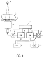
- the x-ray system shown in FIG. 1 comprises an x-ray emitter 1 which shines through a patient 3 located on a table top 2.
- the X-ray relief produced in this way is fed to the input screen of an image intensifier 4, the output image of which is enhanced in brightness is recorded by a television camera 5.
- the input screen of the amplifier 4 is curved, which leads to the fact that the image provided by the image amplifier has pillow-shaped distortions. Further, less pronounced distortions are caused by the influence of the earth's magnetic field and by the video camera 5.
- the analog video signal supplied by the video camera 5 is converted by an analog-digital converter 6 into a sequence of digital data words which are stored in a memory 10 under successive addresses. This is controlled by a video control unit 7.
- the memory 10, which thus contains the distorted input image is connected via a bus system 9 to a microcomputer 8, which also has access to further memories 11 and 12 via this bus system.
- the memory 11 serves to record the output image which has been freed from distortions by the transformation.
- the output image values can be read out from the memory 11 and fed via a digital-to-analog converter 13 to a display unit (monitor) which is not shown in detail.
- the distorted input image (B i ) is contained in the memory 10.
- an equalized image (B o ) is generated in the memory 11 by the transformation.
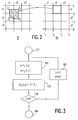
- FIG. 2 shows a section of the image matrix of the input image B i and the output image B o .
- the section shows an area of 3 x 3 picture elements.
- the picture elements have a square shape. In principle, however, other shapes are also possible, for example a rectangular one Shape or a hexagonal shape.
- the picture elements of the input image B i are characterized by their position, ie by their coordinates u, v (with u (u1, u2, u3%) And v (v1, v2, v3.7) (x1, x2, x3%) and y (y1, y2, y3...) the position of the picture elements in the output picture.
- the picture elements in the output picture are marked laterally by lines i (i1, i2, i3...) and in the height is limited by lines j (j1, j2, j3...) Such boundary lines are also present in the input image B i , but their naming is not necessary for the method according to the invention.
- the intersections of two lines i, j each define a corner point.
- N is 512.
- the discrete values for u, v or x, y, which characterize the position of a picture element (or its center point) in the input image B i or in the output image B o are preferably integer values.
- Each combination u, v in the input image B i or x, y in the output image B o is assigned a memory location with a specific address in the memory 10 or 11.
- the first step of the method consists in determining the spatial association with the picture elements of the input picture, starting from the picture elements of the output picture. While in the known methods for this purpose the length of a single point, e.g. of the center point is calculated and it is assumed that the position and size remain unchanged, in the method according to the invention the position of several points is calculated per picture element, namely of all (four) corner points. Nevertheless, the computational effort for these calculations is only slightly greater, because apart from the corner points on the image edges, each corner point of a picture element belongs to three further picture elements. Instead of N x N calculations, the invention requires (N + 1) x (N + 1) calculations.
- the image values of the output image are referred to below as B o (x, y) and the image values of the input image B i (u, v).
- Fig. 3 shows that the four corner points of the picture element of the output image with the coordinates x2, y1 in the input image pass into the four points P1, P2, P3 and P4. Furthermore, it is assumed that the four straight lines in the output picture, which connect the four corner points, also merge into straight lines in the input picture, so that a polygon - with four corner points a square - results. This assumption is not completely exact (the connecting lines between the points P1 ... P4 can also be curved lines), but it is a very good approximation.
- the calculation in block 103 is based on the consideration that the output image value is formed by the weighted sum of the input image values of those picture elements in the input image which are represented by the square P 1. . . P4 be covered.
- the input image values are included in the output image value the greater the area that covers the square in the image in question. These areas are designated according to Fig. 2 with F1. . .
- the output image value corresponds to the integral of the input image values over the area of the square.
- the position u, v in the input image is then again calculated in method step 102 for the new line of corner points of the output image.
- the computational effort could be reduced by Coordinates u, v calculated once for all corner points of the initial image (in the form of an address list). This would increase the storage effort considerably, particularly if differently distorted input images are to be processed, such as in tomosynthesis, in which a large number of X-ray recordings are made with X-rays impinging on the image intensifier 4 from different radiation source positions. Therefore, the recalculation of the position of the corner points for each image is preferred, because in this case only one set of polynomial coefficients a0 for each input image. . . a5 and b0. . . b5 must be stored (see equations (1) and (2)).
- the corner points of the input image are assumed, and it is first determined which position is assigned to these corner points in the output image.
- the four corner points in the input image define a square (e.g. P1 ... P4) in the output image, which covers several image elements (here: 4).
- a (partial) output picture value is derived from the input picture value of the associated picture element in the input picture, which corresponds to the ratio between the area of the picture element covered by the square to the total area of the square.
- the (partial) output image value dB o for the image elements covered by the square in the output image is derived from the input image value of the associated image element in the input image (block 203).
- B i u2, v2).
- dB O (x2, y2) c ⁇ F4 / F O ⁇ B i (u2, v2) (4)
- c is a constant
- F o the total area of the through the points P1. . . P4 defined quadrilaterals in the initial image
- F4 the partial area of the picture element x2, y2, which is covered by the quadrilateral.
- the output image value B0 (x2, y2) depends not only on the input image value B i (u2, v2), but also on the input image values B i (u1, v2), B i (u1, v3) and B i (u2, v3), which belong to picture elements that are below and / or next to the picture element u2, v2 in the input image.
- the value dB o is added to the output image value, which is stored in the memory 11 for the relevant output image element.
- the coordinates of the corner points in the output image can be determined in columns instead of in rows.
- the calculated coordinates can be calculated once and stored in an address list in order to be used in subsequent equalization operations.
Landscapes
- Engineering & Computer Science (AREA)
- Physics & Mathematics (AREA)
- General Physics & Mathematics (AREA)
- Theoretical Computer Science (AREA)
- Multimedia (AREA)
- Signal Processing (AREA)
- Image Processing (AREA)
- Apparatus For Radiation Diagnosis (AREA)
- Image Analysis (AREA)
Applications Claiming Priority (2)
| Application Number | Priority Date | Filing Date | Title |
|---|---|---|---|
| DE4316847A DE4316847A1 (de) | 1993-05-19 | 1993-05-19 | Verfahren zum Entzerren von Röntgenaufnahmen und Anordnung zur Durchführung des Verfahrens |
| DE4316847 | 1993-05-19 |
Publications (2)
| Publication Number | Publication Date |
|---|---|
| EP0625762A1 true EP0625762A1 (fr) | 1994-11-23 |
| EP0625762B1 EP0625762B1 (fr) | 2001-10-24 |
Family
ID=6488529
Family Applications (1)
| Application Number | Title | Priority Date | Filing Date |
|---|---|---|---|
| EP94201342A Expired - Lifetime EP0625762B1 (fr) | 1993-05-19 | 1994-05-11 | Méthode de correction des images radiographiques et dispositif de réalisation de la méthode |
Country Status (4)
| Country | Link |
|---|---|
| US (1) | US5671297A (fr) |
| EP (1) | EP0625762B1 (fr) |
| JP (1) | JP3672588B2 (fr) |
| DE (2) | DE4316847A1 (fr) |
Cited By (3)
| Publication number | Priority date | Publication date | Assignee | Title |
|---|---|---|---|---|
| DE19542355A1 (de) * | 1995-11-14 | 1997-05-15 | Hans Thilo Richter | Verfahren und Vorrichtung zur Erzeugung eines Weitwinkelbildes |
| WO2002089059A3 (fr) * | 2001-04-25 | 2003-05-30 | Siemens Ag | Procede de traitement d'image |
| US9229970B2 (en) | 2009-12-07 | 2016-01-05 | International Business Machines Corporation | Methods to minimize communication in a cluster database system |
Families Citing this family (14)
| Publication number | Priority date | Publication date | Assignee | Title |
|---|---|---|---|---|
| EP0881051A1 (fr) * | 1997-05-27 | 1998-12-02 | Sumitomo Chemical Company, Limited | Procédé pour mouler au gaz par injection un objet creux |
| US6038548A (en) * | 1997-11-26 | 2000-03-14 | International Business Machines Corporation | System and method for conducting electronic commerce in a computer network using a cashier desk payment framework |
| JP3684479B2 (ja) * | 1999-09-01 | 2005-08-17 | 株式会社日立製作所 | デジタルカメラ |
| US7067414B1 (en) | 1999-09-01 | 2006-06-27 | Micron Technology, Inc. | Low k interlevel dielectric layer fabrication methods |
| US6975755B1 (en) | 1999-11-25 | 2005-12-13 | Canon Kabushiki Kaisha | Image processing method and apparatus |
| GB2359884B (en) * | 1999-11-25 | 2004-06-30 | Canon Kk | Image processing method and apparatus |
| US6671349B1 (en) | 2000-11-13 | 2003-12-30 | Olganix Corporation | Tomosynthesis system and registration method |
| DE10141085A1 (de) * | 2001-08-22 | 2003-05-15 | Siemens Ag | Röntgendiagnostikeinrichtung mit einer Bildvorverarbeitung und Verfahren zur Entzerrung von Bildern |
| US7302111B2 (en) * | 2001-09-12 | 2007-11-27 | Micronic Laser Systems A.B. | Graphics engine for high precision lithography |
| US6707998B2 (en) | 2002-05-14 | 2004-03-16 | Eastman Kodak Company | Method and system for correcting non-symmetric distortion in an image |
| US7327390B2 (en) * | 2003-02-04 | 2008-02-05 | Eastman Kodak Company | Method for determining image correction parameters |
| DE10352411B4 (de) | 2003-11-10 | 2007-02-22 | Yxlon International Security Gmbh | Verfahren zur Entzerrung eines Röntgenbildes eines Gepäckstücks |
| US20050226535A1 (en) * | 2004-04-13 | 2005-10-13 | Srinka Ghosh | Method and system for rectilinearizing an image of a microarray having a non-rectilinear feature arrangement |
| US20050275733A1 (en) * | 2004-06-10 | 2005-12-15 | Philip Chao | Method and apparatus of rendering a video image by polynomial evaluation |
Citations (1)
| Publication number | Priority date | Publication date | Assignee | Title |
|---|---|---|---|---|
| EP0375053A2 (fr) * | 1988-12-22 | 1990-06-27 | Philips Patentverwaltung GmbH | Dispositif de transformation géométrique d'image |
Family Cites Families (4)
| Publication number | Priority date | Publication date | Assignee | Title |
|---|---|---|---|---|
| NL9000766A (nl) * | 1990-04-02 | 1991-11-01 | Koninkl Philips Electronics Nv | Inrichting voor geometrische correctie van een vertekend beeld. |
| US5173948A (en) * | 1991-03-29 | 1992-12-22 | The Grass Valley Group, Inc. | Video image mapping system |
| JP2791231B2 (ja) * | 1991-04-17 | 1998-08-27 | 三菱電機株式会社 | X線画像診断装置の糸巻歪補正方法 |
| GB2256989B (en) * | 1991-06-21 | 1995-02-08 | Sony Broadcast & Communication | Video image capture apparatus |
-
1993
- 1993-05-19 DE DE4316847A patent/DE4316847A1/de not_active Withdrawn
-
1994
- 1994-05-11 EP EP94201342A patent/EP0625762B1/fr not_active Expired - Lifetime
- 1994-05-11 DE DE59409916T patent/DE59409916D1/de not_active Expired - Fee Related
- 1994-05-18 JP JP10406094A patent/JP3672588B2/ja not_active Expired - Fee Related
-
1996
- 1996-03-04 US US08/612,006 patent/US5671297A/en not_active Expired - Fee Related
Patent Citations (1)
| Publication number | Priority date | Publication date | Assignee | Title |
|---|---|---|---|---|
| EP0375053A2 (fr) * | 1988-12-22 | 1990-06-27 | Philips Patentverwaltung GmbH | Dispositif de transformation géométrique d'image |
Non-Patent Citations (2)
| Title |
|---|
| TANG ET AL.: "Image Transformation Approach to Nonlinear Shape Restoration", IEEE TRANSACTIONS ON SYSTEMS, MAN AND CYBERNETICS, vol. 23, no. 1, January 1993 (1993-01-01), NEW YORK US, pages 155 - 172, XP000378057, DOI: doi:10.1109/21.214774 * |
| TEHRANI ET AL.: "HIGH-SPEED DIGITAL RADIOGRAPHIC PINCUSHION DISTORSION, CORRECTION USING AN ARRAY PROCESSOR", COMPUTERS IN TECHNOLOGY, 7 October 1986 (1986-10-07), BOSTON, MASSACHUSETTS, pages 615 - 618 * |
Cited By (3)
| Publication number | Priority date | Publication date | Assignee | Title |
|---|---|---|---|---|
| DE19542355A1 (de) * | 1995-11-14 | 1997-05-15 | Hans Thilo Richter | Verfahren und Vorrichtung zur Erzeugung eines Weitwinkelbildes |
| WO2002089059A3 (fr) * | 2001-04-25 | 2003-05-30 | Siemens Ag | Procede de traitement d'image |
| US9229970B2 (en) | 2009-12-07 | 2016-01-05 | International Business Machines Corporation | Methods to minimize communication in a cluster database system |
Also Published As
| Publication number | Publication date |
|---|---|
| JP3672588B2 (ja) | 2005-07-20 |
| DE4316847A1 (de) | 1994-11-24 |
| US5671297A (en) | 1997-09-23 |
| DE59409916D1 (de) | 2001-11-29 |
| JPH0737080A (ja) | 1995-02-07 |
| EP0625762B1 (fr) | 2001-10-24 |
Similar Documents
| Publication | Publication Date | Title |
|---|---|---|
| EP0625762B1 (fr) | Méthode de correction des images radiographiques et dispositif de réalisation de la méthode | |
| DE68925456T2 (de) | Verfahren zur Bildkontrastverbesserung | |
| DE3886323T2 (de) | Interpolationsverfahren. | |
| DE3348093C2 (fr) | ||
| DE3587155T2 (de) | Verfahren und vorrichtung zum verdichten von bilddaten. | |
| DE2848376C2 (de) | Einrichtung zur Nachkorrektur von Standardfarbkorrekturen bei der Farbbildaufzeichnung | |
| DE3688298T2 (de) | Videosignalverarbeitung. | |
| EP0681269B1 (fr) | Appareil et procédé de réproduction d'une radiographie comme image visible | |
| DE4211385A1 (de) | Daten-projektionssystem | |
| DE4224568C2 (de) | Vorrichtung und Verfahren zur Bildung der Anzeige eines dreidimensionalen sequentiellen tomografischen Flächenschattierungsbildes | |
| DE3209073C2 (de) | Anordnung zum Umsetzen der Zahl von Abtastlinien | |
| DE3788925T2 (de) | Interpolator für Fernsehtricksystem. | |
| EP0375053B1 (fr) | Dispositif de transformation géométrique d'image | |
| DE2804732A1 (de) | Geraet zur verarbeitung von werten einer quantitaet, beispielsweise der absorption von roentgenstrahlung | |
| DE4437385A1 (de) | Verfahren und Vorrichtung zur Bildkorrektur | |
| DE3824977A1 (de) | Bildrotationseinrichtung | |
| DE3751688T2 (de) | Verfahren zur Glättung von Bildsignalen | |
| DE3517995A1 (de) | Anordnung zur fensteranzeige | |
| EP0860696A2 (fr) | Méthode de prise de vues à rayons X avec une série de prises de vues sous différentes perspectives | |
| DE19545776A1 (de) | Abgestufte Anzeige digital komprimierter Wellenformen | |
| DE3317292C2 (de) | Verfahren zum Verbessern einer Gammakamera | |
| DE68926952T2 (de) | Verfahren zur Ausführung von interaktiven Bildverarbeitungsoperationen auf grossen Bildern | |
| DE3485914T2 (de) | Bildverarbeitungsverfahren und -geraet mit feldteilen. | |
| DE3508606C2 (fr) | ||
| DE3880554T2 (de) | Datenerfassungsschaltung. |
Legal Events
| Date | Code | Title | Description |
|---|---|---|---|
| PUAI | Public reference made under article 153(3) epc to a published international application that has entered the european phase |
Free format text: ORIGINAL CODE: 0009012 |
|
| AK | Designated contracting states |
Kind code of ref document: A1 Designated state(s): DE FR GB NL |
|
| 17P | Request for examination filed |
Effective date: 19950523 |
|
| 17Q | First examination report despatched |
Effective date: 19981014 |
|
| RAP3 | Party data changed (applicant data changed or rights of an application transferred) |
Owner name: KONINKLIJKE PHILIPS ELECTRONICS N.V. Owner name: PHILIPS CORPORATE INTELLECTUAL PROPERTY GMBH |
|
| RIC1 | Information provided on ipc code assigned before grant |
Free format text: 7G 06T 3/00 A, 7G 06T 5/00 B |
|
| RTI1 | Title (correction) |
Free format text: METHOD FOR CORRECTING RADIOGRAPHIC IMAGES AND DEVICE FOR ACHIEVING IT |
|
| GRAG | Despatch of communication of intention to grant |
Free format text: ORIGINAL CODE: EPIDOS AGRA |
|
| GRAG | Despatch of communication of intention to grant |
Free format text: ORIGINAL CODE: EPIDOS AGRA |
|
| GRAH | Despatch of communication of intention to grant a patent |
Free format text: ORIGINAL CODE: EPIDOS IGRA |
|
| GRAH | Despatch of communication of intention to grant a patent |
Free format text: ORIGINAL CODE: EPIDOS IGRA |
|
| GRAA | (expected) grant |
Free format text: ORIGINAL CODE: 0009210 |
|
| AK | Designated contracting states |
Kind code of ref document: B1 Designated state(s): DE FR GB NL |
|
| PG25 | Lapsed in a contracting state [announced via postgrant information from national office to epo] |
Ref country code: NL Free format text: LAPSE BECAUSE OF FAILURE TO SUBMIT A TRANSLATION OF THE DESCRIPTION OR TO PAY THE FEE WITHIN THE PRESCRIBED TIME-LIMIT Effective date: 20011024 Ref country code: FR Free format text: LAPSE BECAUSE OF FAILURE TO SUBMIT A TRANSLATION OF THE DESCRIPTION OR TO PAY THE FEE WITHIN THE PRESCRIBED TIME-LIMIT Effective date: 20011024 |
|
| REF | Corresponds to: |
Ref document number: 59409916 Country of ref document: DE Date of ref document: 20011129 |
|
| REG | Reference to a national code |
Ref country code: GB Ref legal event code: IF02 |
|
| GBT | Gb: translation of ep patent filed (gb section 77(6)(a)/1977) |
Effective date: 20020105 |
|
| NLV1 | Nl: lapsed or annulled due to failure to fulfill the requirements of art. 29p and 29m of the patents act | ||
| EN | Fr: translation not filed | ||
| PLBE | No opposition filed within time limit |
Free format text: ORIGINAL CODE: 0009261 |
|
| STAA | Information on the status of an ep patent application or granted ep patent |
Free format text: STATUS: NO OPPOSITION FILED WITHIN TIME LIMIT |
|
| RAP2 | Party data changed (patent owner data changed or rights of a patent transferred) |
Owner name: KONINKLIJKE PHILIPS ELECTRONICS N.V. Owner name: PHILIPS CORPORATE INTELLECTUAL PROPERTY GMBH |
|
| 26N | No opposition filed |
Opponent name: KONINKLIJKE PHILIPS ELECTRONICS N.V. |
|
| REG | Reference to a national code |
Ref country code: GB Ref legal event code: 746 Effective date: 20021107 |
|
| PGFP | Annual fee paid to national office [announced via postgrant information from national office to epo] |
Ref country code: DE Payment date: 20070713 Year of fee payment: 14 |
|
| PGFP | Annual fee paid to national office [announced via postgrant information from national office to epo] |
Ref country code: GB Payment date: 20070522 Year of fee payment: 14 |
|
| GBPC | Gb: european patent ceased through non-payment of renewal fee |
Effective date: 20080511 |
|
| PG25 | Lapsed in a contracting state [announced via postgrant information from national office to epo] |
Ref country code: DE Free format text: LAPSE BECAUSE OF NON-PAYMENT OF DUE FEES Effective date: 20081202 |
|
| PG25 | Lapsed in a contracting state [announced via postgrant information from national office to epo] |
Ref country code: GB Free format text: LAPSE BECAUSE OF NON-PAYMENT OF DUE FEES Effective date: 20080511 |