EP0625866A2 - Strahlungsheizkörper - Google Patents
Strahlungsheizkörper Download PDFInfo
- Publication number
- EP0625866A2 EP0625866A2 EP94303378A EP94303378A EP0625866A2 EP 0625866 A2 EP0625866 A2 EP 0625866A2 EP 94303378 A EP94303378 A EP 94303378A EP 94303378 A EP94303378 A EP 94303378A EP 0625866 A2 EP0625866 A2 EP 0625866A2
- Authority
- EP
- European Patent Office
- Prior art keywords
- dividing wall
- electric heater
- heater according
- radiant electric
- heating elements
- Prior art date
- Legal status (The legal status is an assumption and is not a legal conclusion. Google has not performed a legal analysis and makes no representation as to the accuracy of the status listed.)
- Granted
Links
Images


Classifications
-
- H—ELECTRICITY
- H05—ELECTRIC TECHNIQUES NOT OTHERWISE PROVIDED FOR
- H05B—ELECTRIC HEATING; ELECTRIC LIGHT SOURCES NOT OTHERWISE PROVIDED FOR; CIRCUIT ARRANGEMENTS FOR ELECTRIC LIGHT SOURCES, IN GENERAL
- H05B3/00—Ohmic-resistance heating
- H05B3/68—Heating arrangements specially adapted for cooking plates or analogous hot-plates
- H05B3/74—Non-metallic plates, e.g. vitroceramic, ceramic or glassceramic hobs, also including power or control circuits
- H05B3/748—Resistive heating elements, i.e. heating elements exposed to the air, e.g. coil wire heater
-
- H—ELECTRICITY
- H05—ELECTRIC TECHNIQUES NOT OTHERWISE PROVIDED FOR
- H05B—ELECTRIC HEATING; ELECTRIC LIGHT SOURCES NOT OTHERWISE PROVIDED FOR; CIRCUIT ARRANGEMENTS FOR ELECTRIC LIGHT SOURCES, IN GENERAL
- H05B2203/00—Aspects relating to Ohmic resistive heating covered by group H05B3/00
- H05B2203/017—Manufacturing methods or apparatus for heaters
-
- H—ELECTRICITY
- H05—ELECTRIC TECHNIQUES NOT OTHERWISE PROVIDED FOR
- H05B—ELECTRIC HEATING; ELECTRIC LIGHT SOURCES NOT OTHERWISE PROVIDED FOR; CIRCUIT ARRANGEMENTS FOR ELECTRIC LIGHT SOURCES, IN GENERAL
- H05B2213/00—Aspects relating both to resistive heating and to induction heating, covered by H05B3/00 and H05B6/00
- H05B2213/04—Heating plates with overheat protection means
Definitions
- This invention relates to a radiant electric heater for use in a smooth top cooker and to a smooth top cooker incorporating such a heater.
- a smooth top in a smooth top cooker, overlies one or more heaters comprising a metal dish, for example of circular shape, in which is provided a base layer of thermal and electrical insulating material.
- One or more electrical heating elements is or are supported in the dish, such element or elements comprising coiled wire and/or electrically conducting strip and/or one or more infra-red radiating lamps, for example of tungstenhalogen form.
- a peripheral wall of a thermally insulating material such as a ceramic fibre material or vermiculite, is normally provided around the heater and, when the heater is installed, the peripheral wall contacts the underside of the glass ceramic smooth top with the heating element or elements being spaced from the smooth top.
- a heater incorporating at least two heating elements which are independently energisable and separated by a dividing wall of thermal insulating material.
- separate and distinct heating zones are formed on the smooth top of the cooker so as to enable the heated area of the cooker to be adapted substantially to cooking utensils having different sizes and/or shapes.
- Such a heater is described in GB-A-2 044 057.
- a circular heater including a central heating element and an annular heating element surrounding the central heating element and separated from it by a circular dividing wall of thermally insulating material.
- the central heating element For heating a cooking utensil of small base area the central heating element is arranged to be energised alone.
- the central and annular heating elements are both arranged to be energised together.
- the dividing wall is selected by way of its materials and dimensions to optimise thermal isolation of the inner and outer heating zones from one another, the inner heating zone incorporating the central heating element and the outer heating zone incorporating the annular heating element.
- the dividing wall which is typically of ceramic fibre material, is arranged to extend in height substantially up to the underside of the smooth top of the cooker and has a typical thickness of about 10 to 15 mm, such a thickness being of a similar order of magnitude to the peripheral wall of the heater.
- the material and dimensions of the dividing wall provide an efficient thermal insulation barrier between the inner and outer heating zones such that when only the central heating element is energised, thermal transmission by conduction, convection and radiation from the heated inner zone to the unheated outer zone is minimised. In this way, concentration of heat in the inner zone, that is within the confines of the dividing wall, is maximised, as is the efficiency of heating a cooking utensil placed on the smooth top and covering the area of the inner zone.
- a disadvantage of such a known heater can be the substantial thickness of the dividing wall which, as already stated, is typically 10 mm or more. Such a thickness may, for example, be two, three, or more times the typical distance between adjacent rows of wire coils in a coiled wire heating element and from one aspect can result in a non-uniform temperature across that area of the glass ceramic surface of a cooker heated by the heater, when the elements in the zones on both sides of the dividing wall are energised. From another aspect, the thick dividing wall occupies a significant area of the heater and results in a reduction in available area inside the heater for the heating elements. This problem becomes severe when it is required to provide a heater having more than two mutually isolated heated zones, thereby necessitating two or more dividing walls.
- a radiant electric heater for use in a smooth top cooker, the heater comprising a base of electrical and thermal insulating material; at least two heating elements supported on the base, at least one of which heating elements is energisable independently of the other element or elements; a peripheral wall of thermal insulating material extending laterally around the heating elements; and at least one dividing wall arranged between the heating elements such that, in use, separate and distinct heating zones are formed on the smooth top of the cooker, wherein the at least one dividing wall is received in the base of electrical and thermal insulating material and is retained therein by friction.
- the dividing wall permits the dividing wall to be considerably thinner than hitherto and, in certain embodiments, to be constructed and arranged as a barrier substantially only to thermal convection currents generated in the heater.
- the dividing wall need not, for example, be a barrier to thermal conduction. Consequently, the dividing wall is only required to be of sufficient thickness so as to maintain an upstanding, preferably self-supporting, position during operation of the heater and to comprise a material which will withstand the normal operating temperature range within the heater.
- the dividing wall is maintained in its upstanding position by virtue of the dividing wall being received in the base layer of electrical and thermal insulating material and being retained therein by friction.
- the dividing wall may be partly embedded in the base of electrical and thermal insulation or may be received in a groove formed therein.
- the dividing wall may be of a material selected without substantial regard for its thermal conductivity or thermal radiation transmittance or reflectance properties. Accordingly it is not required to comprise a thermally insulating material in the sense thereof generally accepted by the skilled person.
- the dividing wall may comprise a metal strip, although for electrical safety reasons it may be preferred that the wall comprises an electrically insulating material.
- suitable electrically insulating materials for the dividing wall are: fabrics incorporating glass fibres and/or ceramic fibres; ceramics; mica and other micaceous materials.
- Such a fabric may, if required, be impregnated or coated with a stiffening medium such as a solution of an alkali or alkaline earth silicate solution, or a silica sol, which is subsequently dried.
- the thickness of the dividing wall should typically not exceed 50 percent, and preferably not exceed 30 percent, of the thickness of the peripheral wall of the heater.
- the thickness of the dividing wall is preferably less than 5 mm.
- the dividing wall is preferably constructed of substantially uniform thickness. Its height may be substantially the same as, or slightly less than (for example by 1 to 2 mm) the height of the peripheral wall of the heater.
- two or more heating elements may be concentrically disposed relative to one another, a dividing wall being provided at the or each interface between the heating elements.
- at least one of the heating elements may be disposed laterally of the other heating element or elements, a dividing wall being provided between the laterally disposed heating element and the other heating element or elements.
- the dividing wall may also comprise, or include, or be coated with, a thermal radiation reflecting material, such as alumina.
- Figures 1 and 2 show a radiant electric heater which comprises a metal dish 1 containing a base 2 of electrical and thermal insulating material.
- the insulating material is preferably microporous thermal insulating material which is well known in the art and described, for example, in GB-A-1 580 909.
- a peripheral wall 4 of thermal insulation material comprising, for example, ceramic fibre material, vermiculite or microporous thermal insulation material.
- a typical thickness of the peripheral wall 4 is about 10 mm.
- the heater is intended to be mounted in a smooth top cooker under a glass-ceramic cooking surface 100, with the top surface of the peripheral wall 4 in contact with the underside of the glass-ceramic cooking surface.
- the heating elements may be in the form of elongate electrically conductive strips, preferably corrugated, and partially embedded edgewise in the base 2.
- the heating elements are separated from each other by a circular dividing wall 7 having a height the same as, or slightly less than (for example by 1 to 2 mm), the height of the peripheral wall 4.
- the thickness of the dividing wall 7 is such that it fits into a gap 12 between the heating elements 5 and 6 whose width is substantially the same as the distance d between adjacent turns of the heating element 5.
- the thickness of the dividing wall 7 will not exceed 50 percent of the typical thickness of the peripheral wall 4 and preferably will not exceed 30 percent of the typical thickness of the peripheral wall 4.
- the thickness of the dividing wall 7 is suitably less than 5 mm.
- the dividing wall 7 separates the total heating area defined by the peripheral wall 4 into a central zone and an annular zone.
- the heating element 5 in the central zone is operable independently of the heating element 6 in the annular zone, separate terminal connectors 8 and 9 being provided for elements 5 and 6 respectively.
- the material and thickness of the dividing wall 7 is selected primarily with regard to preventing transmission of heat by thermal convection from the central zone, heated by element 5, to the surrounding annular zone in which is located the element 6. It is not therefore required to be a thermally insulating material in the generally accepted sense thereof and may comprise a metal. However, in the interest of electrical safety it is preferred that the dividing wall should comprise an electrical insulating material.
- a particularly suitable material for the dividing wall 7 is a woven glass fibre fabric, e.g. of thickness about 1 mm or less.
- a fabric may, if desired, be stiffened by coating it, for example, with a sodium silicate solution or aqueous silica sol which is subsequently dried.
- the dividing wall 7 could alternatively comprise a thin ring of a ceramic, ceramic fibre material, mica or other micaceous material.
- the dividing wall 7 is located in position by partially recessing it into the surface of the base 2 so that the dividing wall is retained in the base by friction.
- the dividing wall 7 may either be urged into the surface of the base 2 or into a groove formed in the surface of the base 2. We have found that to retain the dividing wall in place by friction considerably facilitates manufacture and transportation of the radiant heater.
- thermal cut-out device 10 is provided to extend across the heating element 5 in the central zone and is thermally isolated from the heating element 6 in the annular outer zone by means of a block 11 of thermal insulating material which surrounds the cut-out device where it crosses the outer zone. The cut-out device 10 is therefore responsive only to the heating element 5 in the central zone.
- a dividing wall was provided comprising ceramic fibre thermal insulating material and having a thickness of about 10 mm. This thick dividing wall of the prior art was intended to minimise thermal transfer through it by conduction, convection and radiation.
- Both heaters were located beneath a glass-ceramic cook top, and two identical containers, each with one litre of water therein were placed on the glass-ceramic surface overlying the central zone of the heaters.
- the heating element 5 in the central zone of each heater was energised and the time taken for the water in each container to reach boiling point was measured. Very little difference in time was noted, the heater according to the invention with the thin dividing wall taking only a few seconds longer to bring the water to boiling point than the heater of the prior art.
- thermal convection is a prime thermal parameter to be considered in such a heater and the thin dividing wall of the present invention is an effective barrier to thermal convection currents.
- the use of the thin dividing wall in the heater of the invention allows the spacing between the heating elements 5 and 6 in the central and outer zones to be reduced compared with the prior art. Consequently, when both heating elements are energised, a high degree of uniformity of temperature across the entire heater can be achieved.
- a further advantage of the thin dividing wall is that heaters with more than two heating zones can readily be provided by incorporating two or more such dividing walls, without the need to create additional space for the dividing walls. This is primarily because the dividing walls can be inserted in spaces having dimensions such as those normally provided between adjacent rows of elements in a heating coil or strip. Thus the dividing wall according to the present invention gives considerably greater flexibility than has hitherto be available in the design of radiant electric heaters for smooth top cookers.
- the invention is also applicable to heaters incorporating one or more halogen lamps instead of, or in addition to, one or more of the aforementioned heating elements.
- the thin dividing wall 7 may comprise, include, or be coated with a thermal radiation reflecting material, such as, for example, alumina.
- a radiant electric heater comprises a metal dish 1 containing a base 2 of electrical and thermal insulating material. Against the side 3 of the dish 1 is located a peripheral wall 4 of thermal insulation material typically about 10 mm thick.
- Two electric heating elements 13 and 14 in the form of wire coils or strips of metal or metal alloy are located in grooves formed in the base 2.
- the heating elements are separated from each other by an arcuate dividing wall 15 having the same height as, or slightly less than, the height of the peripheral wall 4.
- the dividing wall 15 separates the total heating area defined by the peripheral wall into a circular zone and a crescent-shaped zone.
- the heating element 13 in the circular zone is operable independently of the heating element 14 in the crescent-shaped zone so as to create either a circular heating area or an oval heating area on the smooth top 100 of the cooker.
- Separate terminal connectors 16 and 17 are provided for heating elements 13 and 14 respectively.
- the dividing wall 15 is partially recessed into the surface of the base 2 by urging it into the surface of the base or into a groove formed therein and is retained in the base by friction.
- a thermal cut-out device 10 extends across the heating element 13 in the circular zone.
- the heating elements can also be embedded in the base at the same time.
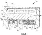
- the press 18 comprises a housing 19, a cover 20, a plunger 21 and a press tool 22.
- the press tool 22 may conveniently be machined from a plastics material such as polytetrafluoroethylene (PTFE) and has a stepped rim 23 and grooves 24, 25 and 26 formed in its upper surface.
- Groove 24 is shaped in the illustrated embodiment to correspond to the configuration of a generally circular dividing wall
- groove 25 is shaped in the illustrated embodiment to correspond to the desired configuration of a generally circular heating element to be positioned within the confines of the dividing wall
- groove 26 is shaped in the illustrated embodiment to correspond to the desired configuration of a generally annular heating element to be positioned around the dividing wall.
- the depth of the grooves is selected to correspond to whatever proportion of the height of the dividing wall or heating element that is desired to be exposed in the resulting heater, i.e. is required not to be embedded in the base of thermal insulation material. Generally it will be desired that a major proportion of the height of the dividing wall and of the heating elements will be exposed.
- the upper end of the housing 19 is recessed to receive the rim of a metal dish 28 which will form the support for the heater.
- Operation of the press 18 commences with retraction of the plunger 21 to the position shown in Figure 5.
- a generally circular dividing wall 29, for example of woven glass fibre material as hereinbefore described, is placed edgewise in the groove 24.
- An inner, generally circular, heating element 30, for example made from an elongate electrically conductive strip of corrugated form, is placed edgewise in the groove 25, and an outer, generally annular, heating element 31 similar to the heating element 30 is placed edgewise in the groove 26.
- a predetermined quantity of powdery microporous insulation mixture 32 (shown in dashed line) is introduced into the press 18 on top of the press tool 22, the dividing wall 29, the inner heating element 30 and the outer heating element 31.
- the metal dish 28 is then placed in the recess in the upper end of the housing 19 and the cover 20 is closed and secured.
- the powdery microporous thermal insulation material is described, for example, in GB-A-1 580 909, a typical composition being: 49 - 97 percent by weight pyrogenic silica 0.5 - 20 percent by weight ceramic fibre reinforcement 2 - 50 percent by weight opacifier (such as titanium dioxide) 0.5 - 12 percent by weight alumina
- the press 18 is operated, for example hydraulically, to urge the plunger 21 and the press tool 22 towards the metal dish 28, thereby compacting the insulation material 32 into the dish 28.
- the material is compacted to a density of, typically, 300 - 400 kg/m3, and the plunger 21 may be held in its final position for a dwell time of several seconds to several minutes if necessary.
- the cover 20 is opened and the dish 28 containing the compacted insulation material 32, the dividing wall 29 and the heating elements 30 and 31 (shown in dashed lines in Figure 5) is removed.
- the dividing wall and the heating elements are found to be partially embedded in the insulation material 32 and are retained in the insulation material by friction.
- a major proportion of the height of the dividing wall and of the heating elements is exposed above the surface of the insulation material, this proportion corresponding to the depth of the grooves 24, 25 and 26 in the press tool 22.
- the insulation material is found to have been firmly compacted around the dividing wall and the heating elements thereby securing the dividing wall and the elements firmly in place in partial embedment in the insulation material.
- Assembly of the remaining components of the heater for example the terminal connectors, peripheral wall, thermal cut-out device and a block of thermal insulation material if needed, as illustrated in Figures 1 and 2, may then be effected.
- apertures or recesses may be provided around the periphery of the dividing wall so as to be embedded in the thermal insulation material. It is found that insulation material enters the apertures or recesses and becomes compacted therein so as to secure the dividing wall more firmly.
- the microporous thermal insulation material may comprise more than one layer, with a main layer of silica-based material being positioned adjacent the base of the metal dish and a surface layer of alumina-based material.
- the surface layer is preferably sufficiently thick for the embedded portions of the dividing wall and of the heating elements to be accommodated entirely within it.
- a suitable composition for the alumina-based material comprises: 55 - 65 percent by weight aluminium oxide 5 - 15 percent by weight silica 25 - 35 percent by weight titanium dioxide 1 - 5 percent by weight ceramic fibre
- the aluminium oxide is in the form of a pyrogenic, or fume, material such as that sold under the name Aluminium Oxide C by Degussa AG.
- the layers may be formed in the metal dish in any suitable manner.
- the material for the silica-based insulation material may first be introduced into the press and compacted using a first press tool, the insulation material being compacted to less than its final density.
- the dividing wall and heating elements may be inserted into a second press tool and the alumina-based insulation material may then be introduced into the press beneath the silica-based material partially compacted into the metal dish.
- the alumina-based material is then compressed onto the silica-based material with the second press tool and the two layers compacted to their final density while simultaneously securing the dividing wall and the heating elements in position in the alumina-based material.
- the two-layer arrangement can be manufactured in a single operation by introducing the alumina-based material into the press on top of the dividing wall and the heating elements and then introducing the silica-based material on top of the alumina-based material.
- the press is then operated to compact the two layers simultaneously and to secure the dividing wall and the heating elements in position.
- the heater may be manufactured in an inverted position. It may be manufactured by placing the powdery insulation material in the metal dish and then bringing the press tool, with the dividing wall and the heating elements held therein, downwardly onto the insulation material to compact it into the dish and to secure the dividing wall and the heating elements in the insulation material. Moreover, it is not necessary simultaneously to secure the dividing wall and the heating elements in the insulation material and the heating elements and/or the dividing wall may be secured subsequently to forming a fully or partially compacted layer of insulation material if desired.
- the insulation material in one or more layers may be first compacted in the dish, preferably to less than the final compaction density, using the first press tool and the heating elements and the dividing wall may then be urged into the insulation material by means of the second press tool, accompanied if necessary by final compaction of the insulation material.
Landscapes
- Chemical & Material Sciences (AREA)
- Engineering & Computer Science (AREA)
- Ceramic Engineering (AREA)
- Resistance Heating (AREA)
- Electric Ovens (AREA)
- Electric Stoves And Ranges (AREA)
- Yarns And Mechanical Finishing Of Yarns Or Ropes (AREA)
- Surface Heating Bodies (AREA)
Applications Claiming Priority (2)
| Application Number | Priority Date | Filing Date | Title |
|---|---|---|---|
| GB9310514 | 1993-05-21 | ||
| GB939310514A GB9310514D0 (en) | 1993-05-21 | 1993-05-21 | Radiant electric heater |
Publications (3)
| Publication Number | Publication Date |
|---|---|
| EP0625866A2 true EP0625866A2 (de) | 1994-11-23 |
| EP0625866A3 EP0625866A3 (de) | 1995-01-11 |
| EP0625866B1 EP0625866B1 (de) | 1997-09-17 |
Family
ID=10735897
Family Applications (1)
| Application Number | Title | Priority Date | Filing Date |
|---|---|---|---|
| EP94303378A Expired - Lifetime EP0625866B1 (de) | 1993-05-21 | 1994-05-11 | Strahlungsheizkörper |
Country Status (8)
| Country | Link |
|---|---|
| US (1) | US5498854A (de) |
| EP (1) | EP0625866B1 (de) |
| AT (1) | ATE158466T1 (de) |
| DE (1) | DE69405645T2 (de) |
| DK (1) | DK0625866T3 (de) |
| ES (1) | ES2106447T3 (de) |
| GB (2) | GB9310514D0 (de) |
| GR (1) | GR3025464T3 (de) |
Cited By (1)
| Publication number | Priority date | Publication date | Assignee | Title |
|---|---|---|---|---|
| EP1146776A3 (de) * | 2000-04-15 | 2001-12-12 | E.G.O. ELEKTRO-GERÄTEBAU GmbH | Strahlungsheizkörper, insbesondere für ein Glaskeramik-Kochfeld |
Families Citing this family (14)
| Publication number | Priority date | Publication date | Assignee | Title |
|---|---|---|---|---|
| DE19644282A1 (de) * | 1996-10-24 | 1998-04-30 | Wacker Chemie Gmbh | Wärmedämmender Formkörper und Verfahren zu seiner Herstellung |
| GB2333406B (en) * | 1998-01-16 | 2001-10-10 | Ceramaspeed Ltd | Radiant electric heater |
| GB2361159B (en) * | 2000-04-03 | 2004-11-03 | Ceramaspeed Ltd | Radiant electric heater |
| GB2361161B (en) * | 2000-04-03 | 2004-11-03 | Ceramaspeed Ltd | Asymmetric radiant heater with multiple heating zones |
| GB2372190B (en) | 2000-12-16 | 2005-02-09 | Ceramaspeed Ltd | Cooking appliance with radiant electric heater |
| GB0811980D0 (en) * | 2008-07-07 | 2008-07-30 | Ceramaspeed Ltd | Radiant electric heater |
| JP7018882B2 (ja) * | 2015-12-31 | 2022-02-14 | アプライド マテリアルズ インコーポレイテッド | 処理チャンバのための高温ヒータ |
| US10718527B2 (en) | 2016-01-06 | 2020-07-21 | James William Masten, JR. | Infrared radiant emitter |
| DE102016224069A1 (de) * | 2016-12-02 | 2018-06-07 | E.G.O. Elektro-Gerätebau GmbH | Kochgerät mit einer Kochplatte und einer Heizeinrichtung darunter |
| US11067288B2 (en) | 2017-05-15 | 2021-07-20 | Backer Ehp Inc. | Dual coil electric heating element |
| US10132504B1 (en) * | 2017-05-15 | 2018-11-20 | Backer Ehp Inc. | Dual coil electric heating element |
| US11581156B2 (en) | 2019-07-03 | 2023-02-14 | Backer Ehp Inc. | Dual coil electric heating element |
| USD955168S1 (en) | 2019-07-03 | 2022-06-21 | Backer Ehp Inc. | Electric heating element |
| US20210041108A1 (en) * | 2019-08-09 | 2021-02-11 | Eidon, Llc | Apparatuses for radiant heating |
Family Cites Families (15)
| Publication number | Priority date | Publication date | Assignee | Title |
|---|---|---|---|---|
| US1475760A (en) * | 1921-10-20 | 1923-11-27 | Westinghouse Electric Products | Inclosed range-heating unit |
| US2029573A (en) * | 1933-08-17 | 1936-02-04 | Knapp Monarch Co | Stove construction |
| GB439571A (en) * | 1934-06-02 | 1935-12-02 | George Henry Collins | Improvements in electric cooking stoves |
| US3277279A (en) * | 1964-01-06 | 1966-10-04 | Wei Tohchung | Electric heater assembly for simultaneously heating a pair of vessels |
| SE8000898L (sv) * | 1979-02-07 | 1980-08-08 | Micropore International Ltd | Anordning vid sleta spishellar |
| DE7930529U1 (de) * | 1979-10-27 | 1980-02-28 | E.G.O. Elektro-Geraete Blanc U. Fischer, 7519 Oberderdingen | Heizelement fuer ein glaskeramik- kochgeraet |
| GR69904B (de) * | 1979-10-27 | 1982-07-20 | Ego Elektro Blanc & Fischer | |
| DE3007037A1 (de) * | 1980-02-26 | 1981-09-03 | Ego Elektro Blanc & Fischer | Glaskeramik-kochgeraet |
| DE3007806C2 (de) * | 1980-02-29 | 1982-09-02 | Elpag AG Chur, 7001 Chur | Elektrische Heizeinrichtung für Herde und Kochplatten |
| DE3163458D1 (en) * | 1980-03-05 | 1984-06-14 | Kenwood Mfg Co Ltd | Cooking apparatus |
| DE3327622A1 (de) * | 1983-07-30 | 1985-02-07 | Blanc Gmbh & Co, 7519 Oberderdingen | Elektrische heizplatte fuer ein glaskeramik-kochfeld |
| GB8412339D0 (en) * | 1984-05-15 | 1984-06-20 | Thorn Emi Domestic Appliances | Heating apparatus |
| GB8514785D0 (en) * | 1985-06-11 | 1985-07-10 | Micropore International Ltd | Infra-red heaters |
| ATE107832T1 (de) * | 1988-05-27 | 1994-07-15 | Ceramaspeed Ltd | Elektrisches strahlungsheizgerät. |
| GB8926289D0 (en) * | 1989-11-21 | 1990-01-10 | Ceramaspeed Ltd | Radiant electric heaters |
-
1993
- 1993-05-21 GB GB939310514A patent/GB9310514D0/en active Pending
-
1994
- 1994-05-11 AT AT94303378T patent/ATE158466T1/de not_active IP Right Cessation
- 1994-05-11 DK DK94303378.7T patent/DK0625866T3/da active
- 1994-05-11 ES ES94303378T patent/ES2106447T3/es not_active Expired - Lifetime
- 1994-05-11 EP EP94303378A patent/EP0625866B1/de not_active Expired - Lifetime
- 1994-05-11 DE DE69405645T patent/DE69405645T2/de not_active Expired - Fee Related
- 1994-05-12 GB GB9409473A patent/GB2278263B/en not_active Expired - Fee Related
- 1994-05-19 US US08/246,325 patent/US5498854A/en not_active Expired - Lifetime
-
1997
- 1997-11-25 GR GR970403113T patent/GR3025464T3/el unknown
Cited By (1)
| Publication number | Priority date | Publication date | Assignee | Title |
|---|---|---|---|---|
| EP1146776A3 (de) * | 2000-04-15 | 2001-12-12 | E.G.O. ELEKTRO-GERÄTEBAU GmbH | Strahlungsheizkörper, insbesondere für ein Glaskeramik-Kochfeld |
Also Published As
| Publication number | Publication date |
|---|---|
| GB2278263A (en) | 1994-11-23 |
| GB2278263B (en) | 1996-07-24 |
| GB9310514D0 (en) | 1993-07-07 |
| GR3025464T3 (en) | 1998-02-27 |
| GB9409473D0 (en) | 1994-06-29 |
| ATE158466T1 (de) | 1997-10-15 |
| EP0625866B1 (de) | 1997-09-17 |
| EP0625866A3 (de) | 1995-01-11 |
| DK0625866T3 (da) | 1998-04-14 |
| ES2106447T3 (es) | 1997-11-01 |
| DE69405645D1 (de) | 1997-10-23 |
| US5498854A (en) | 1996-03-12 |
| DE69405645T2 (de) | 1998-03-05 |
Similar Documents
| Publication | Publication Date | Title |
|---|---|---|
| EP0625866B1 (de) | Strahlungsheizkörper | |
| US4327280A (en) | Smooth top cookers | |
| CA1141413A (en) | Radiant heater unit for smooth top cookers | |
| US4393299A (en) | Electric radiant heater unit for a glass ceramic top cooker | |
| JPH05326121A (ja) | 電気加熱体、特に輻射加熱体 | |
| US4430558A (en) | Electric radiant heater unit for a glass ceramic top cooker | |
| GB1579729A (en) | Electrical heating units | |
| JP4158129B2 (ja) | 輻射電気ヒータ | |
| US5477605A (en) | Method of manufacturing a radiant electric heater | |
| GB2275163A (en) | Mounting radiant electric heater element | |
| US5369874A (en) | Method of manufacturing a radiant electric heater | |
| GB2069300A (en) | Radiant heating elements for smooth top cookers | |
| US5517002A (en) | Radiant electric heater | |
| GB2087698A (en) | Electric radiant heater unit | |
| GB2161348A (en) | Radiation heater reflector | |
| EP0612196B1 (de) | Verfahren zur Herstellung eines elektrischen Strahlungsheizkörpers | |
| US5994674A (en) | Hob | |
| US20040003727A1 (en) | Electrical food warming apparatus | |
| GB2324946A (en) | Radiant electric heater with visible radiation shielding | |
| JPH10302945A (ja) | 輻射電気ヒータ | |
| GB2080660A (en) | Electric radiant heater unit for a glass ceramic top cooker | |
| EP0973356A2 (de) | Elektrischer Strahlungsheizkörper | |
| GB2116010A (en) | Elastic radiant heater units for use in glass ceramic top cookers | |
| GB2275404A (en) | Supporting radiant electrical heating element | |
| KR20000020662U (ko) | 복사 전기 히이터 |
Legal Events
| Date | Code | Title | Description |
|---|---|---|---|
| PUAI | Public reference made under article 153(3) epc to a published international application that has entered the european phase |
Free format text: ORIGINAL CODE: 0009012 |
|
| AK | Designated contracting states |
Kind code of ref document: A2 Designated state(s): AT BE CH DE DK ES FR GR IT LI NL PT SE |
|
| PUAL | Search report despatched |
Free format text: ORIGINAL CODE: 0009013 |
|
| AK | Designated contracting states |
Kind code of ref document: A3 Designated state(s): AT BE CH DE DK ES FR GB GR IT LI NL PT SE |
|
| 17P | Request for examination filed |
Effective date: 19950327 |
|
| GRAG | Despatch of communication of intention to grant |
Free format text: ORIGINAL CODE: EPIDOS AGRA |
|
| GRAH | Despatch of communication of intention to grant a patent |
Free format text: ORIGINAL CODE: EPIDOS IGRA |
|
| 17Q | First examination report despatched |
Effective date: 19970220 |
|
| RBV | Designated contracting states (corrected) |
Designated state(s): AT BE CH DE DK ES FR GR IT LI NL PT SE |
|
| GRAH | Despatch of communication of intention to grant a patent |
Free format text: ORIGINAL CODE: EPIDOS IGRA |
|
| GRAA | (expected) grant |
Free format text: ORIGINAL CODE: 0009210 |
|
| AK | Designated contracting states |
Kind code of ref document: B1 Designated state(s): AT BE CH DE DK ES FR GR IT LI NL PT SE |
|
| PG25 | Lapsed in a contracting state [announced via postgrant information from national office to epo] |
Ref country code: GR Free format text: LAPSE BECAUSE OF FAILURE TO SUBMIT A TRANSLATION OF THE DESCRIPTION OR TO PAY THE FEE WITHIN THE PRESCRIBED TIME-LIMIT Effective date: 19970917 |
|
| REF | Corresponds to: |
Ref document number: 158466 Country of ref document: AT Date of ref document: 19971015 Kind code of ref document: T |
|
| REG | Reference to a national code |
Ref country code: CH Ref legal event code: EP |
|
| REF | Corresponds to: |
Ref document number: 69405645 Country of ref document: DE Date of ref document: 19971023 |
|
| REG | Reference to a national code |
Ref country code: CH Ref legal event code: NV Representative=s name: ISLER & PEDRAZZINI AG |
|
| REG | Reference to a national code |
Ref country code: ES Ref legal event code: FG2A Ref document number: 2106447 Country of ref document: ES Kind code of ref document: T3 |
|
| ET | Fr: translation filed | ||
| ITF | It: translation for a ep patent filed | ||
| REG | Reference to a national code |
Ref country code: PT Ref legal event code: SC4A Free format text: AVAILABILITY OF NATIONAL TRANSLATION Effective date: 19971017 Ref country code: GR Ref legal event code: FG4A Free format text: 3025464 |
|
| REG | Reference to a national code |
Ref country code: DK Ref legal event code: T3 |
|
| PG25 | Lapsed in a contracting state [announced via postgrant information from national office to epo] |
Ref country code: DK Free format text: LAPSE BECAUSE OF NON-PAYMENT OF DUE FEES Effective date: 19980511 |
|
| PG25 | Lapsed in a contracting state [announced via postgrant information from national office to epo] |
Ref country code: BE Free format text: LAPSE BECAUSE OF NON-PAYMENT OF DUE FEES Effective date: 19980531 |
|
| PLBE | No opposition filed within time limit |
Free format text: ORIGINAL CODE: 0009261 |
|
| STAA | Information on the status of an ep patent application or granted ep patent |
Free format text: STATUS: NO OPPOSITION FILED WITHIN TIME LIMIT |
|
| 26N | No opposition filed | ||
| BERE | Be: lapsed |
Owner name: CERAMASPEED LTD Effective date: 19980531 |
|
| PG25 | Lapsed in a contracting state [announced via postgrant information from national office to epo] |
Ref country code: PT Free format text: LAPSE BECAUSE OF NON-PAYMENT OF DUE FEES Effective date: 19981130 |
|
| PG25 | Lapsed in a contracting state [announced via postgrant information from national office to epo] |
Ref country code: NL Free format text: LAPSE BECAUSE OF NON-PAYMENT OF DUE FEES Effective date: 19981201 |
|
| NLV4 | Nl: lapsed or anulled due to non-payment of the annual fee |
Effective date: 19981201 |
|
| REG | Reference to a national code |
Ref country code: PT Ref legal event code: MM4A Free format text: LAPSE DUE TO NON-PAYMENT OF FEES Effective date: 19981130 |
|
| REG | Reference to a national code |
Ref country code: DK Ref legal event code: EBP |
|
| PGFP | Annual fee paid to national office [announced via postgrant information from national office to epo] |
Ref country code: SE Payment date: 20020527 Year of fee payment: 9 Ref country code: CH Payment date: 20020527 Year of fee payment: 9 |
|
| PGFP | Annual fee paid to national office [announced via postgrant information from national office to epo] |
Ref country code: AT Payment date: 20020529 Year of fee payment: 9 |
|
| PG25 | Lapsed in a contracting state [announced via postgrant information from national office to epo] |
Ref country code: AT Free format text: LAPSE BECAUSE OF NON-PAYMENT OF DUE FEES Effective date: 20030511 |
|
| PG25 | Lapsed in a contracting state [announced via postgrant information from national office to epo] |
Ref country code: SE Free format text: LAPSE BECAUSE OF NON-PAYMENT OF DUE FEES Effective date: 20030512 |
|
| PG25 | Lapsed in a contracting state [announced via postgrant information from national office to epo] |
Ref country code: LI Free format text: LAPSE BECAUSE OF NON-PAYMENT OF DUE FEES Effective date: 20030531 Ref country code: CH Free format text: LAPSE BECAUSE OF NON-PAYMENT OF DUE FEES Effective date: 20030531 |
|
| EUG | Se: european patent has lapsed | ||
| REG | Reference to a national code |
Ref country code: CH Ref legal event code: PL |
|
| PGFP | Annual fee paid to national office [announced via postgrant information from national office to epo] |
Ref country code: ES Payment date: 20050411 Year of fee payment: 12 |
|
| PGFP | Annual fee paid to national office [announced via postgrant information from national office to epo] |
Ref country code: DE Payment date: 20050503 Year of fee payment: 12 |
|
| PG25 | Lapsed in a contracting state [announced via postgrant information from national office to epo] |
Ref country code: IT Free format text: LAPSE BECAUSE OF NON-PAYMENT OF DUE FEES;WARNING: LAPSES OF ITALIAN PATENTS WITH EFFECTIVE DATE BEFORE 2007 MAY HAVE OCCURRED AT ANY TIME BEFORE 2007. THE CORRECT EFFECTIVE DATE MAY BE DIFFERENT FROM THE ONE RECORDED. Effective date: 20050511 |
|
| PGFP | Annual fee paid to national office [announced via postgrant information from national office to epo] |
Ref country code: FR Payment date: 20050511 Year of fee payment: 12 |
|
| PG25 | Lapsed in a contracting state [announced via postgrant information from national office to epo] |
Ref country code: ES Free format text: LAPSE BECAUSE OF NON-PAYMENT OF DUE FEES Effective date: 20060512 |
|
| PG25 | Lapsed in a contracting state [announced via postgrant information from national office to epo] |
Ref country code: DE Free format text: LAPSE BECAUSE OF NON-PAYMENT OF DUE FEES Effective date: 20061201 |
|
| REG | Reference to a national code |
Ref country code: FR Ref legal event code: ST Effective date: 20070131 |
|
| REG | Reference to a national code |
Ref country code: ES Ref legal event code: FD2A Effective date: 20060512 |
|
| PG25 | Lapsed in a contracting state [announced via postgrant information from national office to epo] |
Ref country code: FR Free format text: LAPSE BECAUSE OF NON-PAYMENT OF DUE FEES Effective date: 20060531 |