EP0626249B1 - Vorrichtung zur Herstellung von Rohren aus vulkanisiertem Gummi - Google Patents
Vorrichtung zur Herstellung von Rohren aus vulkanisiertem Gummi Download PDFInfo
- Publication number
- EP0626249B1 EP0626249B1 EP94104888A EP94104888A EP0626249B1 EP 0626249 B1 EP0626249 B1 EP 0626249B1 EP 94104888 A EP94104888 A EP 94104888A EP 94104888 A EP94104888 A EP 94104888A EP 0626249 B1 EP0626249 B1 EP 0626249B1
- Authority
- EP
- European Patent Office
- Prior art keywords
- machine according
- cores
- carriage
- frame
- tubes
- Prior art date
- Legal status (The legal status is an assumption and is not a legal conclusion. Google has not performed a legal analysis and makes no representation as to the accuracy of the status listed.)
- Expired - Lifetime
Links
- 238000004519 manufacturing process Methods 0.000 title claims abstract description 20
- 239000004636 vulcanized rubber Substances 0.000 title claims abstract description 9
- 239000000463 material Substances 0.000 claims abstract description 15
- 230000000717 retained effect Effects 0.000 claims description 6
- 229910052751 metal Inorganic materials 0.000 claims description 5
- 239000004677 Nylon Substances 0.000 claims description 2
- 230000000295 complement effect Effects 0.000 claims description 2
- 229920001778 nylon Polymers 0.000 claims description 2
- 230000000284 resting effect Effects 0.000 claims 1
- 230000000694 effects Effects 0.000 description 2
- 238000006073 displacement reaction Methods 0.000 description 1
- 238000011156 evaluation Methods 0.000 description 1
- 239000004744 fabric Substances 0.000 description 1
- 238000010438 heat treatment Methods 0.000 description 1
- 230000000670 limiting effect Effects 0.000 description 1
- 238000012986 modification Methods 0.000 description 1
- 230000004048 modification Effects 0.000 description 1
- 230000002787 reinforcement Effects 0.000 description 1
- 230000001360 synchronised effect Effects 0.000 description 1
- 238000004073 vulcanization Methods 0.000 description 1
- 238000003466 welding Methods 0.000 description 1
- 238000004804 winding Methods 0.000 description 1
Images


Classifications
-
- B—PERFORMING OPERATIONS; TRANSPORTING
- B29—WORKING OF PLASTICS; WORKING OF SUBSTANCES IN A PLASTIC STATE IN GENERAL
- B29C—SHAPING OR JOINING OF PLASTICS; SHAPING OF MATERIAL IN A PLASTIC STATE, NOT OTHERWISE PROVIDED FOR; AFTER-TREATMENT OF THE SHAPED PRODUCTS, e.g. REPAIRING
- B29C53/00—Shaping by bending, folding, twisting, straightening or flattening; Apparatus therefor
- B29C53/56—Winding and joining, e.g. winding spirally
- B29C53/58—Winding and joining, e.g. winding spirally helically
- B29C53/60—Winding and joining, e.g. winding spirally helically using internal forming surfaces, e.g. mandrels
- B29C53/62—Winding and joining, e.g. winding spirally helically using internal forming surfaces, e.g. mandrels rotatable about the winding axis
- B29C53/66—Winding and joining, e.g. winding spirally helically using internal forming surfaces, e.g. mandrels rotatable about the winding axis with axially movable winding feed member, e.g. lathe type winding
-
- B—PERFORMING OPERATIONS; TRANSPORTING
- B29—WORKING OF PLASTICS; WORKING OF SUBSTANCES IN A PLASTIC STATE IN GENERAL
- B29C—SHAPING OR JOINING OF PLASTICS; SHAPING OF MATERIAL IN A PLASTIC STATE, NOT OTHERWISE PROVIDED FOR; AFTER-TREATMENT OF THE SHAPED PRODUCTS, e.g. REPAIRING
- B29C53/00—Shaping by bending, folding, twisting, straightening or flattening; Apparatus therefor
- B29C53/80—Component parts, details or accessories; Auxiliary operations
- B29C53/8008—Component parts, details or accessories; Auxiliary operations specially adapted for winding and joining
- B29C53/8016—Storing, feeding or applying winding materials, e.g. reels, thread guides, tensioners
-
- B—PERFORMING OPERATIONS; TRANSPORTING
- B29—WORKING OF PLASTICS; WORKING OF SUBSTANCES IN A PLASTIC STATE IN GENERAL
- B29C—SHAPING OR JOINING OF PLASTICS; SHAPING OF MATERIAL IN A PLASTIC STATE, NOT OTHERWISE PROVIDED FOR; AFTER-TREATMENT OF THE SHAPED PRODUCTS, e.g. REPAIRING
- B29C35/00—Heating, cooling or curing, e.g. crosslinking or vulcanising; Apparatus therefor
- B29C35/02—Heating or curing, e.g. crosslinking or vulcanizing during moulding, e.g. in a mould
- B29C2035/0211—Heating or curing, e.g. crosslinking or vulcanizing during moulding, e.g. in a mould resistance heating
-
- B—PERFORMING OPERATIONS; TRANSPORTING
- B29—WORKING OF PLASTICS; WORKING OF SUBSTANCES IN A PLASTIC STATE IN GENERAL
- B29K—INDEXING SCHEME ASSOCIATED WITH SUBCLASSES B29B, B29C OR B29D, RELATING TO MOULDING MATERIALS OR TO MATERIALS FOR MOULDS, REINFORCEMENTS, FILLERS OR PREFORMED PARTS, e.g. INSERTS
- B29K2021/00—Use of unspecified rubbers as moulding material
-
- B—PERFORMING OPERATIONS; TRANSPORTING
- B29—WORKING OF PLASTICS; WORKING OF SUBSTANCES IN A PLASTIC STATE IN GENERAL
- B29L—INDEXING SCHEME ASSOCIATED WITH SUBCLASS B29C, RELATING TO PARTICULAR ARTICLES
- B29L2023/00—Tubular articles
- B29L2023/005—Hoses, i.e. flexible
Definitions
- the present invention relates to an improved machine for manufacturing vulcanized-rubber tubes.
- Said machine comprises a pair of heads arranged oppositely with respect to mandrels which rotate two tubular cores supported by supporting elements with fixed rollers on a supporting frame.
- the tubular cores are flanked by a thermally insulated openable box-like container suitable to contain said cores when they are surrounded by the tubes to be vulcanized and after the unloading thereof, which is performed with transfer means.
- the heads of the container are provided with terminal strips for supplying electrical power to the cores and for heating them by means of the Joule effect.
- Means for removing the cores from the container are provided.
- Wrapping of the cores with spirals of the materials to be used to manufacture the tubes is performed with the aid of a carriage which can slide along rails arranged on the ground parallel to said cores.
- An operator is carried on board the carriage from one end of the machine to the other and holds the various coils of material to be wrapped in his hands.
- the operator is capable of performing a single wrapping operation at a time on a single core at a time.
- EP-A-0 231 154 discloses a strip-dispenser carriage for use in the production of tubular elements by winding a flat strip helically onto a rotating core.
- the strip-dispenser includes a carriage frame movable in a direction parallel to the extension of the rotating core, and a slide which is slidably mounted on the carriage frame for displacement with respect to the carriage frame parallel to the direction of movement of the carriage frame.
- the slide carries a flat coil of strip which is rotatably supported in a fixed relative position with respect to the slide.
- the aim of the present invention is to provide a machine for manufacturing vulcanized-rubber tubes which allows higher production yields than current ones and a reduction in assigned personnel.
- a consequent primary object is to eliminate the variable constituted by the skill of the operator during the core wrapping operations.
- Another important object is to provide a machine which allows to manufacture tubes of different types and having different characteristics while always operating in the same conditions.
- Another object is to improve the qualitative yield of machines suitable for manufacturing vulcanized-rubber tubes.
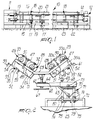
- a machine for manufacturing vulcanized-rubber tubes is generally designated by the reference numeral 10 and comprises two heads, respectively 11 and 12, the first of which is motorized.
- Each head has two mandrels; in figure 1, two first mandrels are designated by the numeral 13 and two second mandrels are designated by the numeral 14.
- Each mandrel is conveniently kinematically connected to an actuation motor, not shown, which is coupled to the head 11.
- the two metallic cores 15 and 16 which are arranged along horizontal parallel axes at different heights with respect to the floor, are supported by roller supports, respectively 17 and 18, which are spaced to avoid excessive flexing during production and are fixed to a frame 19 made of metallic profiled elements.
- Each support 17 or 18 comprises three rollers which are arranged parallel to the corresponding core 15 or 16 to allow said core to rest and roll with low friction and thus allow the unhindered wrapping of spirals of canvas and crude rubber for tube manufacture.
- Said cores 15 and 16 are flanked by a thermally insulated box-like container 20 which is provided with an upper lid 21 which is pivoted thereto and can thus be opened by means of appropriate lever systems, not illustrated.
- the machine 10 is also provided with transfer means, not shown for the sake of simplicity, which are suitable to remove the wrapped cores 15 and 16 and to empty the inside of the box-like container 20, and with means, also not shown for the sake of simplicity, for removing said cores 15 and 16 from the container 20 after vulcanisation, which is performed by means of the Joule effect with the aid of electrical connection terminal strips, also not shown.
- Said cores 15 and 16 are arranged in front of a longitudinal rail 22 which is fixed to the ground; a carriage 23 can slide on said rail and, according to the invention, carries means suitable to wrap said cores 15 and 16 simultaneously.
- Said means for simultaneously wrapping said cores comprise, with reference to figures 2 to 11, a frame 24 which is supported, as more clearly specified hereinafter, by the carriage 23 and is constituted by a base 25 which can rotate and be blocked about a vertical axis and from which two wings, respectively 26 and 27, diverge; said wings extend so that they move above the cores 15 and 16 by virtue of the rotation of the base 25.
- Each wing bears two pairs of supports 28 and 29, to which the ends of corresponding shafts 30 and 31 are rotatably coupled; said shafts support reels 32 and 33, and respectively 32a and 33a, on which ribbons of the materials suitable to form the tubes, for example rubber ribbons 34 and 35, canvas or rubberized-fabric ribbons 34a and 35a, etc., are wound.
- each support of the pairs 28 and 29, for example the support 29 with reference to figures 6 to 8 is constituted by a cradle-shaped element 36 made of nylon, which is advantageously externally covered by a shaped metallic element 37 which is provided with feet 38 and is fixed to the frame 24 by means of screws 39.
- the shaped element 37 is semicircular, and two diametrically opposite portions thereof are joined, by means of a cross-member 40 which is welded thereto; an end of a connecting rod 43 is articulated, by means of a pivot 42, between the fork-like ends of a tab 41 of said crossmember; the opposite end of said connecting rod 43 is articulated to a fork-like element 44 which is fixed to a metallic support 45 which supports a sliding block 46 which is located between the wings of the cradle-like element 36, closing the rotation seat of the end of the corresponding shaft 31.
- Articulation between the connecting rod 43 and the fork-like element 44 is provided by means of the pivot-like end of a bar 47 which connects each support of the pair 28 to the corresponding support of the pair 29.
- a cylindrical helical spring 50 are fixed between said bar 47 and a lever 49 which is pivoted on the frame 24; when the sliding blocks 46 are arranged in the cradle-like elements 36, said spring has the function of transmitting a pressure from said cradle-like elements to the shafts 30 and 31 and opposing the unwinding of the reels 32 and 33 in order to keep the ribbons, for example 34 and 35, stretched.
- Tension is applied to the spring 50 by means of the rotation of the lever 49.
- the spring 50 may be conveniently replaced with an electromagnetic or equivalent brake.
- the articulation of the connecting rods 43 allows the disengagement of the shafts 30 and 31 from their respective seats and the replacement of the reels 32 and 33.
- Each wing 26 or 27 of the frame 24 supports, in a downward region, a pair of parallel bars 51; a respective tubular element 52 can slide on each of said bars, and said tubular element can be locked by means of a locking screw 53 provided with a knob; said screw is rigidly coupled to a bar 54, and the ends of cross-members, designated by the reference numerals 56 for the wing 26 and 57 for the wing 27, are articulated to the ends of said bar 54 by means of pivots 55.
- the cross-members 56 and 57 support guiding means for the ribbons; specifically, in the case of the first guiding means, assigned to the rubber ribbons 34 and 35, said means are constituted by a pair of cylindrical bars 58 which are supported between two wings 59 which extend from the crossmembers 56 and between which the ribbon is passed; in the case of the second guiding means, assigned to the ribbons 34a and 35a, said means are constituted by a roller 60 which is rotatably retained between wings 61 which extend from the cross-members 57.
- the bars 58 or the roller 60 adjust the inclination of the ribbons with respect to the cores 15 and 16; this inclination can be changed by varying the position of the cross-members 56 and 57 by moving the tubular elements 52 along the bars 51.
- the base 25 of the frame 24 can rotate and can be locked about a vertical axis; in particular, it is rigidly coupled to a vertical pivot 62 which is rotatably retained to a horizontal tubular support 63 which it crosses.
- Said pivot 62 is rigidly coupled to, and concentric with, a first disk-like element 64 which rests on a second disk-like element 65 which is also concentric and is rigidly coupled to the support 63.
- Angular registration notches 66 are provided between the disk-like elements 64 and 65 for positioning the wings 26 and 27 with respect to the cores 15 and 16.
- Locking occurs by means of a lower handwheel 67 which screws onto the corresponding threaded end of the pivot 62.
- the support 63 can slide in a tubular guide 68, the cross-section of which is complementary to that of said support.
- Mutual locking of the parts can be performed by means of a screw 69 provided with a knob.
- the tubular guide 68 is diametrically fixed to a disk-like plate 70 which can rotate on the upper part of a secondary carriage 71 which is in turn slideable along parallel guides 72, fixed above the carriage 23 and arranged longitudinally and parallel with respect to the cores 15 and 16.
- said disk-like plate 70 is provided with an axial pivot, not shown in the figures, which is fitted on the secondary carriage 71 and can be locked, with the guide 68 arranged at right angles to the parallel guides 72, by means of a pin 73 which passes through it in a through hole and enters a corresponding through hole of the secondary carriage 71.
- Said secondary carriage 71 is constituted by a framework, made of metallic elements, to the side of which pairs of wheels 74 are rotatably coupled; the guides 72 are arranged between said wheels and, as shown in the figures, are constituted by tubular bars.
- each pair of wheels 74 is connected by plates 75.
- a crankshaft 77 is rotatably coupled to supports 76; a bar 79 is suspended from its crank-shaped portion by means of a rod-like tab 78 which is articulated thereto; said bar 79 extends between the guides 72 and rests against said guides in a downward region.
- a lever 80 is fixed to the shaft 77 and raises or lowers the bar 79, locking it against the guides 72 or spacing it from them, thus locking or releasing the movement of the secondary carriage 71.
- the carriage 23 is motorized for advancement in a synchronous manner with respect to the rotation of the cores 15 and 16, which also rotate synchronously, so as to obtain uniform and constant wrapping of said cores and thus have a uniform thickness of the tubes being manufactured and thus better qualitative results.
- a frame is mounted on the carriage 23 and supports a first rod 90 from which a second rod 91 extends laterally.
- the two rods 90 and 91 which are arranged at right angles above the two cores 15 and 16, are embraced by a tubular element 92 which supports screw elements 93 for fixing.
- a structure 94 is fixed, for example by welding, on said tubular element 92; said structure rotatably supports two redirection rollers 95 for said wires 88 and 89 and a tubular guide 96 for said wires.
- the wires 88 and 89 pass through adapted holes 97 and 98 of the structure 94.
- Each head of the rods 90 and 91 supports redirection rollers, respectively 99 and 100, and bars, respectively 101 and 102, with guiding holes, respectively 103 and 104, for each one of the wires 88 and 89, so as to move them above the respective cores 15 and 16 for wrapping, as shown in figure 13.
- the materials employed may be any according to the requirements.
Landscapes
- Engineering & Computer Science (AREA)
- Mechanical Engineering (AREA)
- Heating, Cooling, Or Curing Plastics Or The Like In General (AREA)
- Rigid Pipes And Flexible Pipes (AREA)
- Lining Or Joining Of Plastics Or The Like (AREA)
- Shaping Of Tube Ends By Bending Or Straightening (AREA)
- Processing And Handling Of Plastics And Other Materials For Molding In General (AREA)
- Moulding By Coating Moulds (AREA)
Claims (23)
- Maschine (10) zur Herstellung von Rohren aus vulkanisiertem Gummi, mit einem Paar von Köpfen (11, 12), die gegenüberliegend Dornen (13, 14) angeordnet sind, welche zwei oder mehr rohrförmige Kerne (15, 16) drehen, die durch Halterungselemente (17, 18) mit festen Rollen auf einem Halterungsgestell (19) gehaltert sind, wobei die rohrförmigen Kerne durch einen thermisch isolierten, zu öffnenden, kastenartigen Behälter (20) flankiert sind, der zur Aufnahme der Kerne geeignet ist, die mit den zu vulkanisierenden Rohren umschlungen sind, und von einer Übertragungsvorrichtung entladen werden; wobei die Köpfe des Behälters eine Vorrichtung zum Liefern elektrischer Energie an die Kerne aufweisen, und eine Vorrichtung zum Entfernen der Kerne von dem Behälter vorgesehen ist; wobei die Maschine einen Schlitten (23) aufweist, der sich entlang Führungen (22) bewegen kann, die parallel zu den Kernen verlaufen; wobei die Maschine dadurch gekennzeichnet ist, daß sie weiterhin eine Umwickelvorrichtung (24 - 33) aufweist, die auf dem Schlitten vorgesehen ist, um die Kerne gleichzeitig mit Spiralen der Materialien zu umwickeln, die zur Herstellung der Rohre verwendet werden, daß die Umwickelvorrichtung ein Gestell (24) aufweist, welche Wickelrollen (32, 33) von Bändern von Materialien trägt, die zum Abwickeln zur Ausbildung der Rohre geeignet sind, und daß das Gestell (24) in bezug auf den Schlitten (23) so bewegt werden kann, daß zumindest entweder eine Rotationsbewegung des Gestells um eine im wesentlichen vertikale Achse oder eine Translationsbewegung des Gestells in eine Richtung vorgesehen ist, die im wesentlichen senkrecht zur Bewegung des Schlittens verläuft.
- Maschine nach Anspruch 1, dadurch gekennzeichnet, daß die Translationsbewegung des Schlittens (23) synchron mit der Drehbewegung der Kerne (15, 16) durchgeführt wird, die sich ebenfalls synchron drehen.
- Maschine nach den voranstehenden Ansprüchen, dadurch gekennzeichnet, daß die Vorrichtungen für das gleichzeitige Umwickeln der Kerne auf einem Gestell (24), welches an dem Schlitten befestigt ist, zumindest zwei Paare von Halterungen (28, 29) umfassen, ein Paar für jeden Kern, an welchen die Enden entsprechender Wellen (30, 31) drehbar gelagert sind, wobei die Wellen jeweilige Wickelrollen (32, 33) haltern, die parallel zu den Kernen liegen, und auf welche Bänder (34, 35) der zur Ausbildung der Rohre geeigneten Materialien aufgewickelt sind.
- Maschine nach Anspruch 3, dadurch gekennzeichnet, daß jede Halterung der Paare durch ein wiegenförmiges Element (36) gebildet ist, das aus Nylon oder aus einem äquivalenten Material hergestellt ist, und welches außen durch ein geformtes Metallelement (37) abgedeckt ist, das an dem Gestell befestigt ist.
- Maschine nach den voranstehenden Ansprüchen, dadurch gekennzeichnet, daß ein Gleitblock (46) an der Halterung durch ein Verbindungsstabsystem (40 - 45) gehaltert ist, wobei der Gleitblock zwischen den Flügeln des wiegenförmigen Elements angeordnet ist, und den Drehsitz des Endes der entsprechenden Welle abschließt.
- Maschine nach den voranstehenden Ansprüchen, dadurch gekennzeichnet, daß das geformte Metallelement (37) halbkreisförmig ist, und daß zwei diametral gegenüberliegende Abschnitte des Elements durch ein Querteil (40) verbunden sind, das damit verbunden ist; daß ein Ende eines Verbindungsstabs (43) mit Hilfe eines Drehzapfens (42) zwischen den gabelartigen Enden einer Zunge (41) des Querteils angelenkt ist, und das entgegengesetzte Ende des Verbindungsstabes an ein gabelartiges Element (44) angelenkt ist, das an einer Metallhalterung (45) befestigt ist, welche den Gleitblock (46) haltert.
- Maschine nach den voranstehenden Ansprüchen, dadurch gekennzeichnet, daß die Anlenkung zwischen dem Verbindungsstab (43) und dem gabelartigen Element (44) durch eine Stange (47) gebildet wird, welche entsprechende Halterungen jedes Paares verbindet, wobei das Ende einer Bremsfeder (50) zwischen der Stange und einem zweiten Hebel (49) befestigt ist, der an das Gestell angelenkt ist.
- Maschine nach Anspruch 5, dadurch gekennzeichnet, daß sie eine elektromagnetische Bremse aufweist, die zwischen der Halterung und dem Gleitblock (46) wirkt.
- Maschine nach den voranstehenden Ansprüchen, dadurch gekennzeichnet, daß das Gestell in einem Bereich nach unten ein Paar paralleler Stangen (51) haltert, wobei ein jeweiliges rohrförmiges Element (52) auf jeder der Stangen gleiten kann, durch eine Verriegelungsschraube (53) verriegelbar ist, und starr mit einer Stange (54) gekuppelt ist, wobei die Enden von Querteilen (56, 57), welche eine Führungsvorrichtung für die Bänder haltern, an den Enden der Stange angelenkt sind.
- Maschine nach den voranstehenden Ansprüchen, dadurch gekennzeichnet, daß die Führungsvorrichtungen für die Gummibänder (34, 35) durch ein Paar zylindrischer Stangen (58) gebildet werden, die zwischen zwei Flügeln (59) gehaltert sind, welche von dem entsprechenden Querteil (56) ausgehen, wobei das entsprechende Band zum Durchgang zwischen den Stangen veranlaßt wird.
- Maschine nach den voranstehenden Ansprüchen, dadurch gekennzeichnet, daß die Führungsvorrichtungen für Bänder (34a, 35a) aus Segeltuch oder gummiertem Segeltuch durch eine Rolle (60) gebildet werden, die drehbar zwischen zwei Flügeln (61) gehaltert ist, die von dem entsprechenden Querteil (57) ausgehen.
- Maschine nach den voranstehenden Ansprüchen, dadurch gekennzeichnet, daß das Gestell (24) durch eine Basis (25) gebildet wird, von welcher zwei Flügel (26, 27) abzweigen, wobei jeder Flügel zwei Paare der Wickelrollenhalterungen (28, 29) in einem oberen Bereich und zwei Paare der Führungsvorrichtungen in einem unteren Bereich haltert.
- Maschine nach Anspruch 12, dadurch gekennzeichnet, daß die Basis des Gestells drehbar ist, und um eine Vertikalachse verriegelt werden kann, und starr mit einem vertikalen Drehzapfen (62) gekuppelt ist, der drehbar an einer horizontalen Halterung (63) angelenkt ist, durch welche er hindurchgeht.
- Maschine nach den voranstehenden Ansprüchen, dadurch gekennzeichnet, daß der Drehzapfen (62) starr mit einem ersten scheibenartigen Element (64) gekuppelt ist und konzentrisch zu diesem verläuft, welches auf einem zweiten scheibenartigen Element (65) aufsitzt, welches ebenfalls konzentrisch zur Halterung (63) angeordnet ist, und starr mit dieser gekuppelt ist, wobei Winkelausrichtungskerben (66) zwischen den scheibenartigen Elementen vorgesehen sind, und ein Verriegelungshandrad (67) in einem Bereich nach unten vorgesehen ist, und auf das entsprechende Gewindeende des vertikalen Drehzapfens aufgeschraubt ist.
- Maschine nach den voranstehenden Ansprüchen, dadurch gekennzeichnet, daß die Halterung (63) in einer rohrförmigen Führung (68) gleitbeweglich ist, welche einen entsprechenden Querschnitt aufweist, wobei die Verriegelung zwischen den Teilen mit Hilfe einer Schraube (69) durchgeführt wird.
- Maschine nach den voranstehenden Ansprüchen, dadurch gekennzeichnet, daß die rohrförmige Führung (68) gegenüberliegend einer scheibenförmigen Platte (70) befestigt ist, die auf dem oberen Teil eines Sekundärschlittens (71) drehbar ist, der wiederum auf Parallelführungen (72) gleiten kann, die oberhalb des Schlittens (23) befestigt sind, und in Längsrichtung der Kerne (15, 16) und parallel zu diesen angeordnet ist.
- Maschine nach den voranstehenden Ansprüchen, dadurch gekennzeichnet, daß die scheibenartige Platte (70) mit einem axialen Drehzapfen versehen ist, der auf den Sekundärschlitten (71) aufgepaßt ist, und mit Hilfe eines Stiftes (73) verriegelt werden kann, wobei die rohrförmige Führung (68) in rechten Winkeln zu den Führungen des Sekundärschlittens verläuft.
- Maschine nach den voranstehenden Ansprüchen, dadurch gekennzeichnet, daß der Sekundärschlitten (71) durch eine Gestellanordnung aus Metallelementen gebildet wird, an deren Seite Paare von Rädern (74) drehbeweglich angeschlossen sind, wobei die Führungen zwischen den Rädern angeordnet sind.
- Maschine nach den voranstehenden Ansprüchen, dadurch gekennzeichnet, daß eine Kurbelwelle (77) drehbar mit Halterungen (76) auf dem Sekundärschlitten (71) gekuppelt ist, in rechten Winkeln zu dessen Führungen (72), eine Stange (79) von dem kurbelförmigen Abschnitt der Kurbelwelle mit Hilfe einer stabförmigen Zunge (78) abgeht, die dort angelenkt ist, wobei die Stange zwischen den Führungen verläuft und auf diesen aufliegt, und ein Hebel (80) an der Welle befestigt ist, um die Stange anzuheben oder abzusenken, durch Bewegung der Stange auf solche Weise, daß sie auf den Führungen verriegelt wird oder sich von diesen wegbewegt.
- Maschine nach den voranstehenden Ansprüchen, dadurch gekennzeichnet, daß die Vorrichtungen (24 - 33) für das gleichzeitige Umwickeln der Kerne (15, 16) einen Stab (90, 91) für jeden Kern aufweisen, der einstellbar auf einem Gestell angeordnet werden kann, das an dem Schlitten (63) befestigt ist, und in rechten Winkeln zu den Kernen angeordnet ist, wobei der Stab Elemente zum Führen und Umlenken eines Drahts (88, 89) haltert, der um die Kerne herumgewickelt werden soll.
- Maschine nach Anspruch 20, dadurch gekennzeichnet, daß die Umlenkungselemente durch Rollen (95) gebildet werden.
- Maschine nach Anspruch 20, dadurch gekennzeichnet, daß die Führungselemente durch Lochstangen (96) gebildet werden, durch welche die Drähte hindurchgehen.
- Maschine nach den voranstehenden Ansprüchen, dadurch gekennzeichnet, daß die Umwickelvorrichtungen einen Hilfsschlitten (81) aufweisen, der dem Schlitten (23) zugeordnet ist, und Halterungen (82, 83) für Wickelrollen (86, 87) trägt, auf welche die Drähte aufgewickelt sind.
Applications Claiming Priority (2)
| Application Number | Priority Date | Filing Date | Title |
|---|---|---|---|
| ITPD930122A IT1263372B (it) | 1993-05-26 | 1993-05-26 | Macchina perfezionata per la produzione di tubi in gomma vulcanizzata. |
| ITPD930122 | 1993-05-26 |
Publications (2)
| Publication Number | Publication Date |
|---|---|
| EP0626249A1 EP0626249A1 (de) | 1994-11-30 |
| EP0626249B1 true EP0626249B1 (de) | 1998-08-19 |
Family
ID=11390350
Family Applications (1)
| Application Number | Title | Priority Date | Filing Date |
|---|---|---|---|
| EP94104888A Expired - Lifetime EP0626249B1 (de) | 1993-05-26 | 1994-03-28 | Vorrichtung zur Herstellung von Rohren aus vulkanisiertem Gummi |
Country Status (7)
| Country | Link |
|---|---|
| US (2) | US5512127A (de) |
| EP (1) | EP0626249B1 (de) |
| AT (1) | ATE169861T1 (de) |
| AU (1) | AU675124B2 (de) |
| CA (1) | CA2124244A1 (de) |
| DE (1) | DE69412539T2 (de) |
| IT (1) | IT1263372B (de) |
Families Citing this family (39)
| Publication number | Priority date | Publication date | Assignee | Title |
|---|---|---|---|---|
| IT1263372B (it) * | 1993-05-26 | 1996-08-05 | Deregibus A & A Spa | Macchina perfezionata per la produzione di tubi in gomma vulcanizzata. |
| IT1281861B1 (it) * | 1995-04-12 | 1998-03-03 | Deregibus Tubigomma | Macchina, particolarmente per la produzione di tubi in gomma vulcanizzata |
| US7294563B2 (en) * | 2000-08-10 | 2007-11-13 | Applied Materials, Inc. | Semiconductor on insulator vertical transistor fabrication and doping process |
| US7223676B2 (en) * | 2002-06-05 | 2007-05-29 | Applied Materials, Inc. | Very low temperature CVD process with independently variable conformality, stress and composition of the CVD layer |
| US20070042580A1 (en) * | 2000-08-10 | 2007-02-22 | Amir Al-Bayati | Ion implanted insulator material with reduced dielectric constant |
| US6893907B2 (en) | 2002-06-05 | 2005-05-17 | Applied Materials, Inc. | Fabrication of silicon-on-insulator structure using plasma immersion ion implantation |
| US6939434B2 (en) * | 2000-08-11 | 2005-09-06 | Applied Materials, Inc. | Externally excited torroidal plasma source with magnetic control of ion distribution |
| US7166524B2 (en) * | 2000-08-11 | 2007-01-23 | Applied Materials, Inc. | Method for ion implanting insulator material to reduce dielectric constant |
| US7465478B2 (en) * | 2000-08-11 | 2008-12-16 | Applied Materials, Inc. | Plasma immersion ion implantation process |
| US7479456B2 (en) * | 2004-08-26 | 2009-01-20 | Applied Materials, Inc. | Gasless high voltage high contact force wafer contact-cooling electrostatic chuck |
| US7303982B2 (en) * | 2000-08-11 | 2007-12-04 | Applied Materials, Inc. | Plasma immersion ion implantation process using an inductively coupled plasma source having low dissociation and low minimum plasma voltage |
| US7183177B2 (en) * | 2000-08-11 | 2007-02-27 | Applied Materials, Inc. | Silicon-on-insulator wafer transfer method using surface activation plasma immersion ion implantation for wafer-to-wafer adhesion enhancement |
| US7320734B2 (en) * | 2000-08-11 | 2008-01-22 | Applied Materials, Inc. | Plasma immersion ion implantation system including a plasma source having low dissociation and low minimum plasma voltage |
| US7037813B2 (en) * | 2000-08-11 | 2006-05-02 | Applied Materials, Inc. | Plasma immersion ion implantation process using a capacitively coupled plasma source having low dissociation and low minimum plasma voltage |
| US7137354B2 (en) * | 2000-08-11 | 2006-11-21 | Applied Materials, Inc. | Plasma immersion ion implantation apparatus including a plasma source having low dissociation and low minimum plasma voltage |
| US7094670B2 (en) | 2000-08-11 | 2006-08-22 | Applied Materials, Inc. | Plasma immersion ion implantation process |
| US7288491B2 (en) * | 2000-08-11 | 2007-10-30 | Applied Materials, Inc. | Plasma immersion ion implantation process |
| US7430984B2 (en) * | 2000-08-11 | 2008-10-07 | Applied Materials, Inc. | Method to drive spatially separate resonant structure with spatially distinct plasma secondaries using a single generator and switching elements |
| US20050230047A1 (en) * | 2000-08-11 | 2005-10-20 | Applied Materials, Inc. | Plasma immersion ion implantation apparatus |
| US7355687B2 (en) * | 2003-02-20 | 2008-04-08 | Hunter Engineering Company | Method and apparatus for vehicle service system with imaging components |
| US7244474B2 (en) * | 2004-03-26 | 2007-07-17 | Applied Materials, Inc. | Chemical vapor deposition plasma process using an ion shower grid |
| US20050211547A1 (en) * | 2004-03-26 | 2005-09-29 | Applied Materials, Inc. | Reactive sputter deposition plasma reactor and process using plural ion shower grids |
| US7695590B2 (en) * | 2004-03-26 | 2010-04-13 | Applied Materials, Inc. | Chemical vapor deposition plasma reactor having plural ion shower grids |
| US20050211171A1 (en) * | 2004-03-26 | 2005-09-29 | Applied Materials, Inc. | Chemical vapor deposition plasma reactor having an ion shower grid |
| US20050211546A1 (en) * | 2004-03-26 | 2005-09-29 | Applied Materials, Inc. | Reactive sputter deposition plasma process using an ion shower grid |
| US7291360B2 (en) * | 2004-03-26 | 2007-11-06 | Applied Materials, Inc. | Chemical vapor deposition plasma process using plural ion shower grids |
| US8058156B2 (en) * | 2004-07-20 | 2011-11-15 | Applied Materials, Inc. | Plasma immersion ion implantation reactor having multiple ion shower grids |
| US7767561B2 (en) * | 2004-07-20 | 2010-08-03 | Applied Materials, Inc. | Plasma immersion ion implantation reactor having an ion shower grid |
| US7666464B2 (en) * | 2004-10-23 | 2010-02-23 | Applied Materials, Inc. | RF measurement feedback control and diagnostics for a plasma immersion ion implantation reactor |
| US7428915B2 (en) * | 2005-04-26 | 2008-09-30 | Applied Materials, Inc. | O-ringless tandem throttle valve for a plasma reactor chamber |
| US7109098B1 (en) | 2005-05-17 | 2006-09-19 | Applied Materials, Inc. | Semiconductor junction formation process including low temperature plasma deposition of an optical absorption layer and high speed optical annealing |
| US20060260545A1 (en) * | 2005-05-17 | 2006-11-23 | Kartik Ramaswamy | Low temperature absorption layer deposition and high speed optical annealing system |
| US7422775B2 (en) * | 2005-05-17 | 2008-09-09 | Applied Materials, Inc. | Process for low temperature plasma deposition of an optical absorption layer and high speed optical annealing |
| US7312162B2 (en) * | 2005-05-17 | 2007-12-25 | Applied Materials, Inc. | Low temperature plasma deposition process for carbon layer deposition |
| US7335611B2 (en) * | 2005-08-08 | 2008-02-26 | Applied Materials, Inc. | Copper conductor annealing process employing high speed optical annealing with a low temperature-deposited optical absorber layer |
| US7323401B2 (en) * | 2005-08-08 | 2008-01-29 | Applied Materials, Inc. | Semiconductor substrate process using a low temperature deposited carbon-containing hard mask |
| US7429532B2 (en) * | 2005-08-08 | 2008-09-30 | Applied Materials, Inc. | Semiconductor substrate process using an optically writable carbon-containing mask |
| US7312148B2 (en) * | 2005-08-08 | 2007-12-25 | Applied Materials, Inc. | Copper barrier reflow process employing high speed optical annealing |
| KR20090106617A (ko) * | 2007-01-19 | 2009-10-09 | 어플라이드 머티어리얼스, 인코포레이티드 | 플라스마 함침 챔버 |
Family Cites Families (17)
| Publication number | Priority date | Publication date | Assignee | Title |
|---|---|---|---|---|
| GB276047A (en) * | 1926-05-05 | 1927-08-05 | Christian Hamilton Gray | An improved process and apparatus for covering cylindrical rollers with rubber |
| US2262636A (en) * | 1939-07-14 | 1941-11-11 | Lehon Co | Method of and means for making tubular articles |
| US2804907A (en) * | 1955-06-27 | 1957-09-03 | Minnesota Mining & Mfg | Helical tape applying apparatus |
| US3401073A (en) * | 1965-02-01 | 1968-09-10 | Simms T S Co Ltd | Paint roller covering applying machine |
| US3522122A (en) * | 1967-06-16 | 1970-07-28 | Ganahl Carl De | Reinforced plastic pipe |
| US3730795A (en) * | 1968-12-18 | 1973-05-01 | Koppers Co Inc | Filament winding method |
| DE2142015A1 (de) * | 1970-09-10 | 1972-04-13 | Westland Aircraft Ltd | Verfahren zum Verdichten von aus Fäden oder Band gewickelten rohrförmigen Gegenständen |
| US4010054A (en) * | 1971-05-03 | 1977-03-01 | Albert L. Jeffers | Thermoplastic filament winding process |
| IT1188303B (it) * | 1986-01-23 | 1988-01-07 | Colbachini Spa | Carrello nastratore,particolarmente studiato per la realizzazione di elementi tubolari flessibili |
| US4838971A (en) * | 1987-02-19 | 1989-06-13 | Brunswick Corporation | Filament winding process and apparatus |
| JPH06336B2 (ja) * | 1989-02-09 | 1994-01-05 | 日東紡績株式会社 | 繊維強化プラスチック成形用プリフォーム及びその製造方法 |
| US5307038A (en) * | 1989-03-28 | 1994-04-26 | Ogura Clutch Co., Ltd. | Electromagnetic coupling apparatus |
| US5145543A (en) * | 1989-04-14 | 1992-09-08 | Thiokol Corporation | Combination filament winding and tape laying apparatus and method for making and using the same |
| US4997503A (en) * | 1989-07-19 | 1991-03-05 | Phillips Petroleum Company | Filament winding apparatus and method |
| IT1233543B (it) * | 1989-07-28 | 1992-04-03 | Deregibus A & A Spa | Macchina per la produzione di tubi in gomma vulcanizzata. |
| CA2057225C (en) * | 1990-12-19 | 1994-09-27 | John A. Johnson | Band fiber forming and placement delivery head |
| IT1263372B (it) * | 1993-05-26 | 1996-08-05 | Deregibus A & A Spa | Macchina perfezionata per la produzione di tubi in gomma vulcanizzata. |
-
1993
- 1993-05-26 IT ITPD930122A patent/IT1263372B/it active IP Right Grant
- 1993-12-20 US US08/169,252 patent/US5512127A/en not_active Expired - Lifetime
-
1994
- 1994-03-28 DE DE69412539T patent/DE69412539T2/de not_active Expired - Fee Related
- 1994-03-28 EP EP94104888A patent/EP0626249B1/de not_active Expired - Lifetime
- 1994-03-28 AT AT94104888T patent/ATE169861T1/de not_active IP Right Cessation
- 1994-05-25 CA CA002124244A patent/CA2124244A1/en not_active Abandoned
- 1994-05-26 AU AU63374/94A patent/AU675124B2/en not_active Ceased
-
1996
- 1996-04-10 US US08/588,182 patent/US5718798A/en not_active Expired - Fee Related
Also Published As
| Publication number | Publication date |
|---|---|
| EP0626249A1 (de) | 1994-11-30 |
| AU675124B2 (en) | 1997-01-23 |
| ITPD930122A1 (it) | 1994-11-26 |
| ATE169861T1 (de) | 1998-09-15 |
| IT1263372B (it) | 1996-08-05 |
| CA2124244A1 (en) | 1994-11-27 |
| US5512127A (en) | 1996-04-30 |
| DE69412539D1 (de) | 1998-09-24 |
| DE69412539T2 (de) | 1999-01-28 |
| AU6337494A (en) | 1994-12-01 |
| US5718798A (en) | 1998-02-17 |
| ITPD930122A0 (it) | 1993-05-26 |
Similar Documents
| Publication | Publication Date | Title |
|---|---|---|
| US5512127A (en) | Machine for manufacturing vulcanized-rubber tubes | |
| EP0258533B1 (de) | Vorrichtung zum Einbringen einer Wickelhülse in eine Wickelmaschine | |
| CA1318900C (en) | Apparatus for winding webs of material | |
| CH679993A5 (de) | ||
| EP0296113A1 (de) | Transportgerät für Weberei | |
| EP1253083B1 (de) | Bahnspannungsvorrichtung | |
| CA1316803C (en) | Welding apparatus for welding plastic webs | |
| US20080087369A1 (en) | Method And Apparatus For Forming Annular Concentric-Lay Bead Cord | |
| CN120172204B (zh) | 一种焊丝生产用收卷装置 | |
| EP0289749B1 (de) | Vorrichtung zum Abwickeln einer Materialbahn von einer Rolle | |
| EP0268544B1 (de) | Vorrichtung zum Auflegen eines kontinuierlichen Elastomerstreifens auf eine Oberfläche | |
| US8033203B2 (en) | Slitting knife cartridge | |
| US5524804A (en) | Lock-out device for threading in a strip guide apparatus | |
| DE1901415A1 (de) | Zufuehrungsvorrichtung fuer den Aufbau von mehrlagigen Reifen | |
| EP0278924B1 (de) | Automatische Vorrichtung zur Formung von Windungen für Spulen, insbesondere geeignet für Dipol- oder Quadrupolmagnete | |
| EP1218277B1 (de) | Speicherspule mit aufgewickeltem zwischenband | |
| TH19621A (th) | เครื่องแบบที่ปรับปรุงขึ้นสำหรับผลิตท่อยางวัลคาไนซ์ | |
| TH11597B (th) | เครื่องแบบที่ปรับปรุงขึ้นสำหรับผลิตท่อยางวัลคาไนซ์ | |
| CN224240441U (zh) | 碳纤维管材卷制设备 | |
| EP0737563B1 (de) | Vorrichtung zur Herstellung von Rohren aus vulkanisiertem Gummi | |
| KR102541680B1 (ko) | 자동 랩핑장치 | |
| CA2004602A1 (en) | Apparatus for feeding a preferably multi-ply web of synthetic thermoplastics | |
| CN114783762A (zh) | 变压器高压线圈绕卷成型装置 | |
| SU1715696A1 (ru) | Устройство дл установки и размотки рулонов | |
| JPH04341445A (ja) | 自動巻付け方法及び装置 |
Legal Events
| Date | Code | Title | Description |
|---|---|---|---|
| PUAI | Public reference made under article 153(3) epc to a published international application that has entered the european phase |
Free format text: ORIGINAL CODE: 0009012 |
|
| AK | Designated contracting states |
Kind code of ref document: A1 Designated state(s): AT BE CH DE DK ES FR GB GR IE IT LI LU NL PT SE |
|
| 17P | Request for examination filed |
Effective date: 19950408 |
|
| 17Q | First examination report despatched |
Effective date: 19960725 |
|
| GRAG | Despatch of communication of intention to grant |
Free format text: ORIGINAL CODE: EPIDOS AGRA |
|
| GRAG | Despatch of communication of intention to grant |
Free format text: ORIGINAL CODE: EPIDOS AGRA |
|
| GRAH | Despatch of communication of intention to grant a patent |
Free format text: ORIGINAL CODE: EPIDOS IGRA |
|
| GRAH | Despatch of communication of intention to grant a patent |
Free format text: ORIGINAL CODE: EPIDOS IGRA |
|
| GRAA | (expected) grant |
Free format text: ORIGINAL CODE: 0009210 |
|
| AK | Designated contracting states |
Kind code of ref document: B1 Designated state(s): AT BE CH DE DK ES FR GB GR IE IT LI LU NL PT SE |
|
| PG25 | Lapsed in a contracting state [announced via postgrant information from national office to epo] |
Ref country code: NL Free format text: LAPSE BECAUSE OF FAILURE TO SUBMIT A TRANSLATION OF THE DESCRIPTION OR TO PAY THE FEE WITHIN THE PRESCRIBED TIME-LIMIT Effective date: 19980819 Ref country code: LI Free format text: LAPSE BECAUSE OF FAILURE TO SUBMIT A TRANSLATION OF THE DESCRIPTION OR TO PAY THE FEE WITHIN THE PRESCRIBED TIME-LIMIT Effective date: 19980819 Ref country code: GR Free format text: LAPSE BECAUSE OF NON-PAYMENT OF DUE FEES Effective date: 19980819 Ref country code: ES Free format text: THE PATENT HAS BEEN ANNULLED BY A DECISION OF A NATIONAL AUTHORITY Effective date: 19980819 Ref country code: CH Free format text: LAPSE BECAUSE OF FAILURE TO SUBMIT A TRANSLATION OF THE DESCRIPTION OR TO PAY THE FEE WITHIN THE PRESCRIBED TIME-LIMIT Effective date: 19980819 |
|
| REF | Corresponds to: |
Ref document number: 169861 Country of ref document: AT Date of ref document: 19980915 Kind code of ref document: T |
|
| REG | Reference to a national code |
Ref country code: CH Ref legal event code: EP |
|
| REF | Corresponds to: |
Ref document number: 69412539 Country of ref document: DE Date of ref document: 19980924 |
|
| ET | Fr: translation filed | ||
| REG | Reference to a national code |
Ref country code: IE Ref legal event code: FG4D |
|
| PG25 | Lapsed in a contracting state [announced via postgrant information from national office to epo] |
Ref country code: SE Free format text: LAPSE BECAUSE OF FAILURE TO SUBMIT A TRANSLATION OF THE DESCRIPTION OR TO PAY THE FEE WITHIN THE PRESCRIBED TIME-LIMIT Effective date: 19981119 Ref country code: PT Free format text: LAPSE BECAUSE OF FAILURE TO SUBMIT A TRANSLATION OF THE DESCRIPTION OR TO PAY THE FEE WITHIN THE PRESCRIBED TIME-LIMIT Effective date: 19981119 Ref country code: DK Free format text: LAPSE BECAUSE OF FAILURE TO SUBMIT A TRANSLATION OF THE DESCRIPTION OR TO PAY THE FEE WITHIN THE PRESCRIBED TIME-LIMIT Effective date: 19981119 |
|
| NLV1 | Nl: lapsed or annulled due to failure to fulfill the requirements of art. 29p and 29m of the patents act | ||
| REG | Reference to a national code |
Ref country code: CH Ref legal event code: PL |
|
| PG25 | Lapsed in a contracting state [announced via postgrant information from national office to epo] |
Ref country code: LU Free format text: LAPSE BECAUSE OF NON-PAYMENT OF DUE FEES Effective date: 19990328 Ref country code: GB Free format text: LAPSE BECAUSE OF NON-PAYMENT OF DUE FEES Effective date: 19990328 |
|
| PLBE | No opposition filed within time limit |
Free format text: ORIGINAL CODE: 0009261 |
|
| STAA | Information on the status of an ep patent application or granted ep patent |
Free format text: STATUS: NO OPPOSITION FILED WITHIN TIME LIMIT |
|
| 26N | No opposition filed | ||
| GBPC | Gb: european patent ceased through non-payment of renewal fee |
Effective date: 19990328 |
|
| PGFP | Annual fee paid to national office [announced via postgrant information from national office to epo] |
Ref country code: IE Payment date: 20040226 Year of fee payment: 11 |
|
| PGFP | Annual fee paid to national office [announced via postgrant information from national office to epo] |
Ref country code: DE Payment date: 20040322 Year of fee payment: 11 |
|
| PGFP | Annual fee paid to national office [announced via postgrant information from national office to epo] |
Ref country code: BE Payment date: 20040324 Year of fee payment: 11 |
|
| PGFP | Annual fee paid to national office [announced via postgrant information from national office to epo] |
Ref country code: FR Payment date: 20040330 Year of fee payment: 11 Ref country code: AT Payment date: 20040330 Year of fee payment: 11 |
|
| PG25 | Lapsed in a contracting state [announced via postgrant information from national office to epo] |
Ref country code: IT Free format text: LAPSE BECAUSE OF NON-PAYMENT OF DUE FEES;WARNING: LAPSES OF ITALIAN PATENTS WITH EFFECTIVE DATE BEFORE 2007 MAY HAVE OCCURRED AT ANY TIME BEFORE 2007. THE CORRECT EFFECTIVE DATE MAY BE DIFFERENT FROM THE ONE RECORDED. Effective date: 20050328 Ref country code: IE Free format text: LAPSE BECAUSE OF NON-PAYMENT OF DUE FEES Effective date: 20050328 Ref country code: AT Free format text: LAPSE BECAUSE OF NON-PAYMENT OF DUE FEES Effective date: 20050328 |
|
| PG25 | Lapsed in a contracting state [announced via postgrant information from national office to epo] |
Ref country code: BE Free format text: LAPSE BECAUSE OF NON-PAYMENT OF DUE FEES Effective date: 20050331 |
|
| BERE | Be: lapsed |
Owner name: *DEREGIBUS A. & A. S.P.A. Effective date: 20050331 |
|
| PG25 | Lapsed in a contracting state [announced via postgrant information from national office to epo] |
Ref country code: DE Free format text: LAPSE BECAUSE OF NON-PAYMENT OF DUE FEES Effective date: 20051001 |
|
| PG25 | Lapsed in a contracting state [announced via postgrant information from national office to epo] |
Ref country code: FR Free format text: LAPSE BECAUSE OF NON-PAYMENT OF DUE FEES Effective date: 20051130 |
|
| REG | Reference to a national code |
Ref country code: IE Ref legal event code: MM4A |
|
| REG | Reference to a national code |
Ref country code: FR Ref legal event code: ST Effective date: 20051130 |
|
| BERE | Be: lapsed |
Owner name: *DEREGIBUS A. & A. S.P.A. Effective date: 20050331 |