EP0626316A1 - Vorrichtung zum einbringen eines gegenstandes in eine hülle - Google Patents
Vorrichtung zum einbringen eines gegenstandes in eine hülle Download PDFInfo
- Publication number
- EP0626316A1 EP0626316A1 EP94903037A EP94903037A EP0626316A1 EP 0626316 A1 EP0626316 A1 EP 0626316A1 EP 94903037 A EP94903037 A EP 94903037A EP 94903037 A EP94903037 A EP 94903037A EP 0626316 A1 EP0626316 A1 EP 0626316A1
- Authority
- EP
- European Patent Office
- Prior art keywords
- wrapping
- opening
- bags
- movable support
- box
- Prior art date
- Legal status (The legal status is an assumption and is not a legal conclusion. Google has not performed a legal analysis and makes no representation as to the accuracy of the status listed.)
- Granted
Links
Images










Classifications
-
- B—PERFORMING OPERATIONS; TRANSPORTING
- B65—CONVEYING; PACKING; STORING; HANDLING THIN OR FILAMENTARY MATERIAL
- B65B—MACHINES, APPARATUS OR DEVICES FOR, OR METHODS OF, PACKAGING ARTICLES OR MATERIALS; UNPACKING
- B65B67/00—Apparatus or devices facilitating manual packaging operations; Sack holders
- B65B67/12—Sack holders, i.e. stands or frames with means for supporting sacks in the open condition to facilitate filling with articles or materials
-
- A—HUMAN NECESSITIES
- A47—FURNITURE; DOMESTIC ARTICLES OR APPLIANCES; COFFEE MILLS; SPICE MILLS; SUCTION CLEANERS IN GENERAL
- A47F—SPECIAL FURNITURE, FITTINGS, OR ACCESSORIES FOR SHOPS, STOREHOUSES, BARS, RESTAURANTS OR THE LIKE; PAYING COUNTERS
- A47F13/00—Shop or like accessories
- A47F13/08—Hand implements, e.g. grocers' scoops, ladles, paper-bag holders
- A47F13/085—Shopping-bag holders
-
- A—HUMAN NECESSITIES
- A45—HAND OR TRAVELLING ARTICLES
- A45B—WALKING STICKS; UMBRELLAS; LADIES' OR LIKE FANS
- A45B25/00—Details of umbrellas
- A45B25/24—Protective coverings for umbrellas when closed
-
- B—PERFORMING OPERATIONS; TRANSPORTING
- B65—CONVEYING; PACKING; STORING; HANDLING THIN OR FILAMENTARY MATERIAL
- B65B—MACHINES, APPARATUS OR DEVICES FOR, OR METHODS OF, PACKAGING ARTICLES OR MATERIALS; UNPACKING
- B65B43/00—Forming, feeding, opening or setting-up containers or receptacles in association with packaging
- B65B43/12—Feeding flexible bags or carton blanks in flat or collapsed state; Feeding flat bags connected to form a series or chain
- B65B43/14—Feeding individual bags or carton blanks from piles or magazines
Definitions
- the present invention relates to a storage device for wrapping bags in order to wrap comparatively long and narrow items.
- the present invention is proposed to provide with simple structure storage device to wrap comparatively long and narrow items, such as French bread, in a wrapping bag.
- the storage device in the present invention comprises: a plurality of wrapping bags which wrap comparatively long and narrow items; a device body in which such a plurality of wrapping bags are stored; and a means which opens openings of said wrapping bags in order to insert said items into such bags.
- the storage device is structured so that said plurality of wrapping bags are firstly stored in a box and the box is filled into the device body.
- the aforementioned wrapping bags which are used for the storage device of the present invention, have openings at the upper parts; the upper end of the fore side of the opening is folded; the upper end of the rear side is projected higher than a verticl positon of the fore side; and locking holes are provided at the upper edge of the projected portion.
- the wrapping bags are applicable to long and narrow items, for example, food stuffs such as French bread and green onions, but not to limited to these items, they are applicable a variety of daily necessities such as umbrellas.
- items such as French bread can be wrapped by using the opening means which opens the openings of the wrapping bags ; in the case that such wrapping bags are entirely consumed, a box in which a plurality of wrapping bags are storeed, can be filled into the device body, and thus, a number of the wrapping bags can be easily replenished into the device's body by a simple and easy operation.
- a number of wrapping bags are stored in one box, there is no danger to scatter them during storing and delivering operation, and the handling can easily be done.
- a number of said wrapping bags can be suspended in order to be retained in the device by penetrating a bar hanger into the locking holes provided at the upper edge of said projected portion.
- the upper ends of the fore side of the openings are folded (e.g. in a U-shape), and thus, a means of bag opening can be certainly inserted into the openings of said wrapping bags in order to open them.
- a device body is not limited to the structure as a casing. It can be structured using pillars, for example. In case that a device body is merely comprised by pillars, transparent members can be arranged between said pillars.
- an umbrella is used as an example of said long and narrow item.
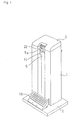
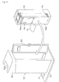
- the charactor (1) is a quadratic prismshaped device body and the case (1) is situated on a bed plate (2) and the closing cover (3) is installed on top of the device body (1).
- a fixed support base (4) is mounted on the inside of the upper device body (1);
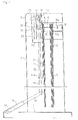
- a hanger (6) which is suspended to store wrapping bags (5) (formed from synthetic resin film and the like) is set on the fixed support base (4).
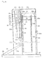
- the hanger (6) is comprised of a bar or similar to be formed in box type (top-open rectangleshaped); the base (6a) is anchored to a hook (not illustrated) and then mounted on the fixed support base (4); and the hanger (6) is installed by hitching both ends (6a,6b) to anchor holes (8a) of support member (8), fixed to the fixed support base (4), for easy removal.
- the top of the wrapping bag (5) has an opening (5a); the upper end (51 a) of the fore side (51) of the opening is folded forward in U-shape; and the upper end (52a) of the rear side (52) is projected above that of the fore side (51); a pair of locking holes (5b) are provided at the upper end of the projected portion.
- a number of wrapping bags are suspended for storage by inserting the opposing member (opposing arm) into each locking hole (5b) of the wrapping bags.
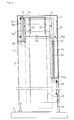
- a movable pressure plate (9) is along the guide bar (10, 10) on the rear face of the wrapping bags (5) and the pressure plate (9) is constantly pressed against the rear face of the wrapping bags (5) by a coil spring (10a) penetrating into each guide bar.
- guide members (14, 15) are mounted ahead of said fixed support base (4); a movable support member (11) in an inverted L-shape, from the front view, is penetrated for storage and to move vertically in holes (14b,15b) formed on horizontal arms (14a, 15a) of such guide members.
- a roller (12) is provided at the upper end of the movable support member (11) that can rotate freely; the roller (12) is arranged along with a box type guide rail (13) and then mounted ahead of the fixed support base (4) to move vertically.
- a foot pedal (16) is provided on said bed plate (2) to lower said movable support member (11). As shown in Figure 4, the foot pedal (16) is mounted or installed with a hinge (17) to move vertically on the bed plate (2).
- a lever (18) is integrally mounted to the pedal (16) and the lever (18) is connected to the lower end of said movable support member (11) through a link (19).
- the charactor (20) is a return spring used to return the movable support member (11) above; the return spring (20) is arranged between a spring bearing (21), comprising of a clip or the like, mounted to a movable support member (11) and a horizontal arm (14a) of said guide member (14) under contracted conditions.
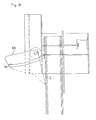
- a pair of open control levers (22, 22) are horizontally provided on the upper central position of said movable support member (11) to rotate in order to open the openings (5a) by entering into the openings (5a) of the wrapping bags; both ends of said levers (22, 22) are integrally connected in the bottom-open rectangle-shape in the illustrated example.
- a moving control arm (23) is integrally provided on one end of both levers (22, 22) to rotate said levers (22, 22); a contacting plate (24) is provided under the arm (23) integral to said guide rail (13); the contacting plate (24) actuates to rotate both levers (22, 22) clockwise in Figure 4 by contacting with said arm (23).
- Sign (25) shows a coil spring; the coil spring (25) is set as a tension coil spring between said moving control arm (23) and the spring bearing (26) connected vertically to one end of the movable support member (11) and allowed to rotate freely; it makes the lower end of said open control levers (22, 22) move and rotate constantly in the direction of the wrapping bags (5).
- the lower end of the open control lever (22) can constantly be moved to rotate in the direction of the wrapping bags (5) by locking one end of a helical spring to the movable support member (11) and by locking the other end of the spring to said open control lever (22); in this case, the helical spring and the like can be arranged around the movable support member (11) close to said open control lever (22).
- each open control lever (22, 22) rotates in clockwise direction against the rotating spring (25) around a fulcrum at a contacting point of said contacting plate (24) in order to open the opening (5a) of the wrapping bag (5).
- the bag (5) in which an umbrella is wrapped can then be removed from the hanger (6) tearing the upper locking holes (5b) of the wrapping bag (5) by pulling the bag out ahead of the device body (1).
- the bag wrapping an umbrella can easily be taken out from the device body (1).
- umbrellas can be easily wrapped in each wrapping bag accurately without using a motor or a vacuum pump and the like in order to open the openings of wrapping bags easily and completely.
- a wrapping bag used in the embodiment shown in Figure 8 to Figure 12 is shown in Figure 8(a) and 8(b).
- the wrapping bag (104) comprises of a plastic film and the like, and as shown in Figure 8, is formed in flat cylinder-shape; the upper part of the wrapping bag has an opening (4a); the upper end (141 a) of the fore side (141) of the opening (104a) is folded in U-shape toward the rear side (142); and the upper end (142a) of the rear side (142) is projected above than that of the fore side (141).
- a pair of locking holes (104b) are provided at the convex upward.
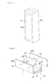
- the aforementioned box (105) is made of corrugated fiberboard; as shown in Figure 9, it is formed in a shape of longitudinal rectangular parallel pipe.
- a pair of bar- shaped hangers (107, 107) are provided on the inside the upper part of said box (105) and said hangers (1007, 107) are penetrated into locking holes (104b) of said wrapping bag (104).
- the hanger (107) is installed to support plates (108a, 108b) fixed to the upper surface inside the box (105).
- a number of wrapping bags (104) can be suspended to retain a state that the fore side (141) faces the left-hand side, as shown in Figure 10.
- a pressure plate (See Figure 12) is arranged on rear face of wrapping bags (104); the pressure plate presses the wrapping bags with an elastic member.
- rubber bands (110) are applied as the elastic members; both ends of the rubber bands (110) are anchored to a hook (181) provided at both sides of the supporting plate (108a).
- an opening (151) which can open along with perforating scores (105a) is provided on the front face of the box (105); the box (105) or the wrapping bags (104) that are stored in the box are transferred and stored without opening (51) when they are not used.
- a switch door (106) provided on the rear side of the device body (1011) to place the box (105) into the device body (1) while opening the opening (151).
- a box type fixed support member is integrally provided inside the device body (101) on the upper part of the box (105) placed in the device body; the positioning is done to contact the fore side of the fixed support member (111) with the front face of said box (105).
- the box (105) storing wrapping bags for umbrellas is charged from the rear side to the device body (101), however, the box can be charged from the top of the device body (101) by configuring, for example, a cover (103) to open.
- a frame body (101b) can be applied as a part of the device body to place the box (105) into the frame (101b) to determine the specified position to retain the box without covering up all faces of the box (105) by the device body (101).
- the opening (4a) of the wrapping bag (4) can be opened by actuating a vacuum suction in the aforementioned prior embodiment without using the open control lever (22) to open the opening (4a) in accordance with the embodiment shown in Figure 1 to Figure 7.
- a pair of horizontal open control levers are structured to move and rotate independently.
- a left-hand side tension coil spring (224) is applied between a left-hand side rotation control arm (223) and said guide rail (216); a right-hand side tension coil spring is applied between a right-hand side rotation control arm (223) and said guide member (212).
- contacting plates (225, 225) are integrally provided on said guide rail (216) and guide member (212); the contacting plates allow each open control lever (222) to rotate in the reverse direction toward a wrapping bag (4) by contacting with the rotating control arm (223) when each open control lever (222) moves lower together with a movable support member (214).
- Tension coil spring is exemplified as means of making each open control lever (222, 222) rotate toward wrapping bags (204), however, for example, a helical spring can be applied as the means, as well.
- each open control lever (222) can be inserted into the opening (204a) by lowering in a good state of contacting with the front face of the upper rear end (242a) of the forefront wrapping bag (204) even some longitudinal misregistration of the opening (204a) in the cross direction to the forefront of the wrapping bag (204) is generated.
- the foot pedal is continuously depressed until an umbrella stored in a wrapping bag is removed from the device body; when the foot pedal is released after the wrapping bag is taken out, the original condition will return through the use of a return spring that ascends to the movable support member.
- the forefront wrapping bag is maintains the opening by applying anchoring as a means to keep lowering the movable support member by pressing the foot pedal until the wrapped umbrella is taken out when the foot pedal is released; for example, as shown in Figure 16, a plurality of locking grooves (226) can be formed on the movable support member (214) and an anchoring claw (227) which hitches to said grooves can be applied to the guide member (213) integrally.
- the movable support member (214) When an umbrella wrapped in a wrapping bag (204) opens the opening (204a) and the umbrella is removed from the from the device body, the movable support member (214) will incline in the direction to release anchoring to the anchoring claw (227) through the open control lever (222). Next, the anchoring a locking groove (214a) to the anchoring claw (227) is released and the movable support member (214) automatically returns to its original position for ascending by elastic rebound of the return spring (220).
- Figure 18 to Figure 20 show the other embodiment of the present invention.
- sign (328) shows a bucket-shaped member formed from plastic integrally. Umbrella insertion can be done easily and completely thanks to the shape of this bucket-shaped member (328). Open wrapping bags (5) with the bucket-shaped member (328) are shown in Figure 19 and Figure 20, however, a detailed explanation is skipped because the state shown in Figure 19 and Figure 20 is almost similar to that in Figure 7(a) to 7(c).
- the opening operation of wrapping bags is done using a foot pedal in the embodiment shown in Figure 1 to Figure 20.
- the openings of the bags are opened without using a foot pedal.
- (401) is a quadratic prism-shaped device body, of which the front, central part is open, situated on a bed plate (402); the closing cover (403) is installed on top of the device body (401).
- a fixed support base (404) is mounted on the inside of the upper device body (401); and a hanger (406), which suspends to store wrapping bags (405), formed from plastic film and the like, is set on the fixed support base (404).
- the hanger (406) is comprised of a bar, and the like formed in a box type (top-open rectangle-shaped), that opens said cover (403) as shown in Figure 25; the base (406a) of the box type hanger (406) is anchored to a hook (407) mounted on a fixed support base (404); and the hanger is installed by hitching both ends (406a,406b) to anchor holes (408a) of the support member (408) fixed to the fixed support base (404) so that it can be removed.
- the upper part of a wrapping bag (405) has an opening (405a); the upper end (451 a) of the fore side (451) of the opening is folded forward in U-shape; the upper end (452a) of the rear side (452) is projected above that of the fore side (451); a pair of locking holes (405b) are provided at the upper end of the projected portion.
- a movable pressure plate (409) is provided along a pair of guide bars (410, 410) on the rear face of a wrapping bag (405) and the pressure plate (409) is constantly pressed towards the rear face of wrapping bag (405) by a coil spring (410a) penetrating into each guide bar.
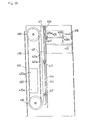
- a box type guide rail (413) is installed at one horizontal end of the front face of said fixed support base (404); a support member (414) is installed at the other horizontal end of the front face of the said base (404); a movable support base (411) is arranged on the front face of the fixed support base (404).
- the movable support base (411) mounts a rotating roller (412) inside the guide rail (413) at one end; as shown in Figure 23, a pair of long holes (416, 416) are vertically formed on the box type guide member (415) mounted on the other end of the movable support base (411); and the movable support base (411) is retained vertical to the fixed support base (404) by hitching a grooved roller (417) to said support member (414).
- a pair of pulleys (418, 418) are installed vertically on said support member (414) forward of said guide member (415) as shown in Figure 22 and Figure 25; a plumb (420) is mounted by screws (420a), and the like, on one side of a belt (419), tensed and rotated with both pulleys (418, 418); and said movable support base (411) moves constantly vertically by connecting the other side of the belt (419) with a connecting member (421) fixed to said guide member (415) by using screws (421 a) and the like.
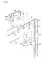
- FIG. 22 A drawing, showing a stopper which is mounted on the fixed support base (404) to anchor the movable support base (411) at the fixed position as shown in Figure 23 so as to limit the ascending motion of the movable support base (411), is omitted.
- signs (413a) and (414a) are stoppers which are formed by bending forward one end of the guide rails (413) and the support member (414) to limit the descending motion of the movable support base (411).
- a pair of supporting axes (423, 424) are provided on the upper central front face of the movable support base (411) through a bearing (416); a movable wear plate (425), which lowers the movable support base (411) by contacting with a shoe at the edge of umbrella, is provided on a supporting axis (423).
- Concave (425a) which contacts with the shoe at the edge of umbrella is formed on the upper central face of the wear plate (425); a curvature (425b) from which is vertically lowered between the movable support base (411) and the fixed support base (404), as shown in Figure 24, is provided at the rear part of the wear plate (25).
- a movable roller (427) is provided through an axis (426) anchored by welding and the like; the upper face of the wear plate can be retained horizontally by contacting the roller (427) with the front face of the fixed support base (404).
- a pair of open control levers (428, 428), which open the openings by entering into the opening (405a) of said wrapping bag (405), are provided on the other supporting axis (424) to be movable in both sides of the wear plate (425); both levers (428, 428) are connected on the upper end with a connecting arm (429) anchored by welding and the like.
- the structure is such that one end of the connecting arm (429) bends forward; by mounting a plumb (430) at the end of the curvature (429a), the open control lever (28) rotates in counterclockwise direction in Figure 24; and the lower end of the lever (28) is pressed to the front face of forefront wrapping bag suspended by a hanger (406).
- a connecting plate (431) which rotates the open control lever (428) in clockwise direction in Figure 24 is integrally provided on the front face of said guide rail (413).
- the open control lever (428) moves downward in a manner by which the end (428a) is pressed to the upper front face of the opening (405a) of the forefront wrapping bag (405); then, the end (428a) of the open control lever (428) enters into the opening (405a) of the wrapping bag (405); in this case, should the upper part (451 a) of the fore side (451) be folded, as mentioned above, the end (428a) of said lever (428) can certainly enter into the opening (405a).
- the wear plate (425) lowers; the roller (427) provided on the curvature (425b) of the wear plate (425) is removed from the central convex (404a) (See Figure 23) of the fixed support base (404); as shown in Figure 27(c), the wear plate (425) sweeps back by rotating in counterclockwise direction around the supporting axis (423); as a result, the shoe (U1) of the edge of umbrella (U) enters into the wrapping bag (405) by slipping on the upper face of the wear plate (425) from the concave (425a) of the wear plate (425); and finally, the umbrella (U) is automatically wrapped into the wrapping bag (405) by further lowering the umbrella (U).
- the bag (405) in which the umbrella (U) is wrapped can be easily taken out together with the umbrella (U) by pulling it out ahead of the device body (401) to remove the upper locking holes (405b) of the wrapping bag (405) from the hanger (406).
- the movable support base (411) and the open control lever (428) automatically returns to the original condition with the plumbs (420, 430) by taking out the umbrella (U) wrapped in the bag (405) forward; the roller (27) provided on the curvature (25b) of the wear plate (25) moves in front of the fixed support base (404); and the wear plate (425) returns horizontal in a standby state.
- the aforementioned embodiment is just an example, therefore, structural changes are possible within the purpose of the present invention.
- the case of storing umbrellas in wrapping bags is just explained, however, the present invention is applicable to storing a variety of food stuffs such as French bread and green onions, to name a few, as well as storing umbrellas.
- an opening of a wrapping bag can be opened by pressing a foot pedal or by pushing long and narrow items into the bags. And then, such items can be easily wrapped by inserting them into the openings of the wrapping bags.
- a number of wrapping bags can easily be stored in the device body collectively and rapidly. Besides, since a number of such wrapping bags are first stored in a box before said box is placed into the device body, it is remarkably easy to carry and store a number of wrapping bags.
Landscapes
- Engineering & Computer Science (AREA)
- Mechanical Engineering (AREA)
- Auxiliary Apparatuses For Manual Packaging Operations (AREA)
- Holders For Apparel And Elements Relating To Apparel (AREA)
- Supplying Of Containers To The Packaging Station (AREA)
- Walking Sticks, Umbrellas, And Fans (AREA)
Applications Claiming Priority (9)
| Application Number | Priority Date | Filing Date | Title |
|---|---|---|---|
| JP92370/92U | 1992-12-22 | ||
| JP9237092 | 1992-12-22 | ||
| JP41131/93U | 1993-06-30 | ||
| JP4113193 | 1993-06-30 | ||
| JP5321071A JP2813292B2 (ja) | 1993-11-26 | 1993-11-26 | 傘の袋収納装置 |
| JP321071/93 | 1993-11-26 | ||
| JP32107093A JP2777326B2 (ja) | 1993-11-26 | 1993-11-26 | 傘の袋収納装置 |
| JP321070/93 | 1993-11-26 | ||
| PCT/JP1993/001853 WO1994014661A1 (fr) | 1992-12-22 | 1993-12-22 | Appareil pour faire rentrer un article dans une housse |
Publications (3)
| Publication Number | Publication Date |
|---|---|
| EP0626316A1 true EP0626316A1 (de) | 1994-11-30 |
| EP0626316A4 EP0626316A4 (de) | 1995-06-14 |
| EP0626316B1 EP0626316B1 (de) | 1999-03-31 |
Family
ID=27461006
Family Applications (1)
| Application Number | Title | Priority Date | Filing Date |
|---|---|---|---|
| EP94903037A Expired - Lifetime EP0626316B1 (de) | 1992-12-22 | 1993-12-22 | Vorrichtung zum einbringen eines gegenstandes in eine hülle |
Country Status (7)
| Country | Link |
|---|---|
| US (1) | US5655352A (de) |
| EP (1) | EP0626316B1 (de) |
| KR (1) | KR0155412B1 (de) |
| DE (1) | DE69324245T2 (de) |
| ES (1) | ES2132374T3 (de) |
| TW (1) | TW249217B (de) |
| WO (1) | WO1994014661A1 (de) |
Cited By (2)
| Publication number | Priority date | Publication date | Assignee | Title |
|---|---|---|---|---|
| FR2732573A1 (fr) * | 1995-04-04 | 1996-10-11 | Daito Sound Co Ltd | Dispositif d'ensachage de parapluies |
| WO2000015515A1 (en) * | 1998-09-15 | 2000-03-23 | Braitrim (Uk) Ltd | Bag dispensing package |
Families Citing this family (10)
| Publication number | Priority date | Publication date | Assignee | Title |
|---|---|---|---|---|
| US5765338A (en) * | 1997-08-05 | 1998-06-16 | Tsai; Hung-Wen | Package bag expanding device |
| DE602004023523D1 (de) * | 2003-08-27 | 2009-11-19 | Muraharu Seisakusho Sagamihara | Einpackvorrichtung für artikel |
| JP2006151401A (ja) * | 2004-11-25 | 2006-06-15 | Niikura Keiryoki Kk | 傘袋収納装置 |
| CA2644323A1 (en) * | 2007-11-20 | 2009-05-20 | Gates Automation, Inc. | Pouch container and method |
| TWI354809B (en) | 2008-06-24 | 2011-12-21 | Ind Tech Res Inst | Composite optical dividing device |
| TWI331230B (en) | 2008-06-27 | 2010-10-01 | Ind Tech Res Inst | Composite optical division device and image apparatus |
| TWI381218B (zh) | 2008-08-08 | 2013-01-01 | Ind Tech Res Inst | 光學色彩分光系統以及所應用的顯示裝置 |
| TW201135285A (en) | 2010-04-01 | 2011-10-16 | Ind Tech Res Inst | Composite color separation system |
| JP6391079B1 (ja) * | 2017-12-26 | 2018-09-19 | 新倉計量器株式会社 | 傘袋束、傘袋束の保持構造、開袋装置 |
| CN113876071A (zh) * | 2021-01-04 | 2022-01-04 | 武汉益途实业有限公司 | 鞋套机装置 |
Family Cites Families (19)
| Publication number | Priority date | Publication date | Assignee | Title |
|---|---|---|---|---|
| US2899788A (en) * | 1959-08-18 | Beebe | ||
| US3468100A (en) * | 1965-09-24 | 1969-09-23 | Atlantic Co | Bagging machine |
| US3385428A (en) * | 1966-10-03 | 1968-05-28 | Kugler Emanuel | Flexible bag |
| GB1328225A (en) * | 1969-11-24 | 1973-08-30 | Grace W R & Co | Packaging apparatus |
| US3747298A (en) * | 1971-11-17 | 1973-07-24 | A Lieberman | Bag dispensing unit and the method of opening and removing the bags therefrom |
| GB1373175A (en) * | 1972-01-10 | 1974-11-06 | Kristiansen A H | Apparatus for the opening and securing of carrier bags during filling of commodities |
| BE795470A (fr) * | 1972-05-12 | 1973-05-29 | Chapuis Ets M | Dispositif automatique pour la presentation de sacs sur une machine d'ensachage avant fermeture |
| JPS5315670Y2 (de) * | 1972-09-20 | 1978-04-25 | ||
| US3783580A (en) * | 1972-10-10 | 1974-01-08 | Union Carbide Corp | Close fitting article packaging system |
| US4368608A (en) * | 1977-07-25 | 1983-01-18 | Texas Aim, Inc. | Automatic ice bagger |
| US4253292A (en) * | 1979-06-12 | 1981-03-03 | Arnold Lipes | Automatic weighing and bagging machine |
| US4370845A (en) * | 1979-08-15 | 1983-02-01 | Perolls Roland F | Methods of and apparatus for closing bag mouths |
| JPS59118711U (ja) * | 1983-01-31 | 1984-08-10 | 株式会社寺岡精工 | 充填包装機における包装用袋の支持構造 |
| FR2592367A1 (fr) * | 1985-12-30 | 1987-07-03 | Castelletta Rene | Dispositif pour distribution de sacs en matiere plastique, en particulier sur des lieux de vente. |
| GB8621259D0 (en) * | 1986-09-03 | 1986-10-08 | W J Morray Engineering Limited | Filling bag with articles |
| JPH01124120U (de) * | 1988-02-18 | 1989-08-23 | ||
| JPH0725377B2 (ja) * | 1990-05-21 | 1995-03-22 | 純市 滝本 | 傘収納袋支持装置 |
| JPH057611U (ja) * | 1991-01-17 | 1993-02-02 | 山田機械工業株式会社 | 傘袋支持装置 |
| EP0626315B1 (de) * | 1992-12-22 | 1998-04-22 | Kabushiki Kaisha Muraharu Seisakusho | Vorrichtung zum einbringen eines schirms in eine hülle |
-
1993
- 1993-12-22 KR KR1019940702795A patent/KR0155412B1/ko not_active Expired - Fee Related
- 1993-12-22 DE DE69324245T patent/DE69324245T2/de not_active Expired - Fee Related
- 1993-12-22 WO PCT/JP1993/001853 patent/WO1994014661A1/ja not_active Ceased
- 1993-12-22 US US08/256,292 patent/US5655352A/en not_active Expired - Fee Related
- 1993-12-22 ES ES94903037T patent/ES2132374T3/es not_active Expired - Lifetime
- 1993-12-22 EP EP94903037A patent/EP0626316B1/de not_active Expired - Lifetime
-
1994
- 1994-01-24 TW TW083100574A patent/TW249217B/zh active
Cited By (2)
| Publication number | Priority date | Publication date | Assignee | Title |
|---|---|---|---|---|
| FR2732573A1 (fr) * | 1995-04-04 | 1996-10-11 | Daito Sound Co Ltd | Dispositif d'ensachage de parapluies |
| WO2000015515A1 (en) * | 1998-09-15 | 2000-03-23 | Braitrim (Uk) Ltd | Bag dispensing package |
Also Published As
| Publication number | Publication date |
|---|---|
| DE69324245T2 (de) | 1999-07-08 |
| HK1017574A1 (en) | 1999-11-19 |
| KR950700193A (ko) | 1995-01-16 |
| ES2132374T3 (es) | 1999-08-16 |
| DE69324245D1 (de) | 1999-05-06 |
| US5655352A (en) | 1997-08-12 |
| KR0155412B1 (ko) | 1999-02-18 |
| EP0626316B1 (de) | 1999-03-31 |
| EP0626316A4 (de) | 1995-06-14 |
| TW249217B (de) | 1995-06-11 |
| WO1994014661A1 (fr) | 1994-07-07 |
Similar Documents
| Publication | Publication Date | Title |
|---|---|---|
| US5655352A (en) | Storage device for wrapping (shopping) bags | |
| US3918589A (en) | Pivoted wicket bag opening dispenser | |
| CA2125946C (en) | Bagging machine with in-line attaching mechanism | |
| EP0781708B1 (de) | Vorrichtung zum einbringen eines schirms in eine hülle | |
| US5526631A (en) | Storage device for umbrella sacks | |
| US5586683A (en) | Storage device for umbrella sacks | |
| US3777439A (en) | Bag-opening dispenser and method | |
| HK1010453B (en) | Apparatus for getting an umbrella received into an umbrella cover | |
| US5314150A (en) | Support stand for golf bag | |
| HK1017574B (en) | Apparatus for getting an article received into a cover | |
| JP2681871B2 (ja) | 傘の袋収納装置およびそれに用いる傘収納袋 | |
| HK1010452B (en) | Apparatus for getting an umbrella received into an umbrella cover | |
| JP2777326B2 (ja) | 傘の袋収納装置 | |
| JPH07156925A (ja) | 傘の袋収納装置 | |
| EP4339031A1 (de) | Vorrichtung zum halten eines oder mehrerer elemente in einem fach eines kraftfahrzeugs | |
| JPH05270522A (ja) | 包装機のリフト装置 | |
| BE1015891A3 (nl) | Rijwielstaander- en stalling. | |
| US5018262A (en) | Belt splicing apparatus | |
| JP2551748Y2 (ja) | 物品受取装置 | |
| EP0309112B1 (de) | Beutelöffnungsvorrichtung | |
| JP4268244B2 (ja) | 葉菜類の袋詰め装置 | |
| JPH0885508A (ja) | 主として野菜類の包装装置 | |
| JPH0454882Y2 (de) | ||
| JPH0730540Y2 (ja) | シート類保管装置 | |
| JPH0146389B2 (de) |
Legal Events
| Date | Code | Title | Description |
|---|---|---|---|
| PUAI | Public reference made under article 153(3) epc to a published international application that has entered the european phase |
Free format text: ORIGINAL CODE: 0009012 |
|
| 17P | Request for examination filed |
Effective date: 19940919 |
|
| AK | Designated contracting states |
Kind code of ref document: A1 Designated state(s): DE ES FR GB IT NL |
|
| A4 | Supplementary search report drawn up and despatched | ||
| AK | Designated contracting states |
Kind code of ref document: A4 Designated state(s): DE ES FR GB IT NL |
|
| 17Q | First examination report despatched |
Effective date: 19960229 |
|
| GRAG | Despatch of communication of intention to grant |
Free format text: ORIGINAL CODE: EPIDOS AGRA |
|
| GRAG | Despatch of communication of intention to grant |
Free format text: ORIGINAL CODE: EPIDOS AGRA |
|
| GRAH | Despatch of communication of intention to grant a patent |
Free format text: ORIGINAL CODE: EPIDOS IGRA |
|
| GRAH | Despatch of communication of intention to grant a patent |
Free format text: ORIGINAL CODE: EPIDOS IGRA |
|
| GRAH | Despatch of communication of intention to grant a patent |
Free format text: ORIGINAL CODE: EPIDOS IGRA |
|
| GRAA | (expected) grant |
Free format text: ORIGINAL CODE: 0009210 |
|
| RAP1 | Party data changed (applicant data changed or rights of an application transferred) |
Owner name: NIIKURA SCALES CO., LTD. Owner name: KABUSHIKI KAISHA MURAHARU SEISAKUSHO |
|
| AK | Designated contracting states |
Kind code of ref document: B1 Designated state(s): DE ES FR GB IT NL |
|
| ITF | It: translation for a ep patent filed | ||
| REF | Corresponds to: |
Ref document number: 69324245 Country of ref document: DE Date of ref document: 19990506 |
|
| ET | Fr: translation filed | ||
| REG | Reference to a national code |
Ref country code: ES Ref legal event code: FG2A Ref document number: 2132374 Country of ref document: ES Kind code of ref document: T3 |
|
| PLBE | No opposition filed within time limit |
Free format text: ORIGINAL CODE: 0009261 |
|
| STAA | Information on the status of an ep patent application or granted ep patent |
Free format text: STATUS: NO OPPOSITION FILED WITHIN TIME LIMIT |
|
| 26N | No opposition filed | ||
| REG | Reference to a national code |
Ref country code: GB Ref legal event code: IF02 |
|
| PGFP | Annual fee paid to national office [announced via postgrant information from national office to epo] |
Ref country code: FR Payment date: 20021026 Year of fee payment: 10 |
|
| PGFP | Annual fee paid to national office [announced via postgrant information from national office to epo] |
Ref country code: GB Payment date: 20021212 Year of fee payment: 10 |
|
| PGFP | Annual fee paid to national office [announced via postgrant information from national office to epo] |
Ref country code: NL Payment date: 20021223 Year of fee payment: 10 |
|
| PGFP | Annual fee paid to national office [announced via postgrant information from national office to epo] |
Ref country code: ES Payment date: 20021230 Year of fee payment: 10 |
|
| PGFP | Annual fee paid to national office [announced via postgrant information from national office to epo] |
Ref country code: DE Payment date: 20030130 Year of fee payment: 10 |
|
| PG25 | Lapsed in a contracting state [announced via postgrant information from national office to epo] |
Ref country code: GB Free format text: LAPSE BECAUSE OF NON-PAYMENT OF DUE FEES Effective date: 20031222 |
|
| PG25 | Lapsed in a contracting state [announced via postgrant information from national office to epo] |
Ref country code: ES Free format text: LAPSE BECAUSE OF NON-PAYMENT OF DUE FEES Effective date: 20031223 |
|
| PG25 | Lapsed in a contracting state [announced via postgrant information from national office to epo] |
Ref country code: NL Free format text: LAPSE BECAUSE OF NON-PAYMENT OF DUE FEES Effective date: 20040701 Ref country code: DE Free format text: LAPSE BECAUSE OF NON-PAYMENT OF DUE FEES Effective date: 20040701 |
|
| GBPC | Gb: european patent ceased through non-payment of renewal fee |
Effective date: 20031222 |
|
| PG25 | Lapsed in a contracting state [announced via postgrant information from national office to epo] |
Ref country code: FR Free format text: LAPSE BECAUSE OF NON-PAYMENT OF DUE FEES Effective date: 20040831 |
|
| NLV4 | Nl: lapsed or anulled due to non-payment of the annual fee |
Effective date: 20040701 |
|
| REG | Reference to a national code |
Ref country code: FR Ref legal event code: ST |
|
| REG | Reference to a national code |
Ref country code: ES Ref legal event code: FD2A Effective date: 20031223 |
|
| PG25 | Lapsed in a contracting state [announced via postgrant information from national office to epo] |
Ref country code: IT Free format text: LAPSE BECAUSE OF NON-PAYMENT OF DUE FEES;WARNING: LAPSES OF ITALIAN PATENTS WITH EFFECTIVE DATE BEFORE 2007 MAY HAVE OCCURRED AT ANY TIME BEFORE 2007. THE CORRECT EFFECTIVE DATE MAY BE DIFFERENT FROM THE ONE RECORDED. Effective date: 20051222 |