EP0626467A1 - Verfahren zur kontinuierlichen aufkohlung eines stahlbandes - Google Patents
Verfahren zur kontinuierlichen aufkohlung eines stahlbandes Download PDFInfo
- Publication number
- EP0626467A1 EP0626467A1 EP93922640A EP93922640A EP0626467A1 EP 0626467 A1 EP0626467 A1 EP 0626467A1 EP 93922640 A EP93922640 A EP 93922640A EP 93922640 A EP93922640 A EP 93922640A EP 0626467 A1 EP0626467 A1 EP 0626467A1
- Authority
- EP
- European Patent Office
- Prior art keywords
- carburizing
- metal strip
- concentration
- furnace
- plate
- Prior art date
- Legal status (The legal status is an assumption and is not a legal conclusion. Google has not performed a legal analysis and makes no representation as to the accuracy of the status listed.)
- Granted
Links
- 238000005255 carburizing Methods 0.000 title claims abstract description 533
- 238000000034 method Methods 0.000 title claims abstract description 56
- 229910000831 Steel Inorganic materials 0.000 title abstract description 92
- 239000010959 steel Substances 0.000 title abstract description 92
- 229910052751 metal Inorganic materials 0.000 claims abstract description 111
- 239000002184 metal Substances 0.000 claims abstract description 111
- 239000000203 mixture Substances 0.000 claims abstract description 81
- 238000009826 distribution Methods 0.000 claims abstract description 58
- 229910052799 carbon Inorganic materials 0.000 claims abstract description 50
- OKTJSMMVPCPJKN-UHFFFAOYSA-N Carbon Chemical compound [C] OKTJSMMVPCPJKN-UHFFFAOYSA-N 0.000 claims abstract description 47
- 239000007789 gas Substances 0.000 claims description 137
- 238000006243 chemical reaction Methods 0.000 claims description 57
- 238000009792 diffusion process Methods 0.000 claims description 44
- 239000002344 surface layer Substances 0.000 claims description 42
- CURLTUGMZLYLDI-UHFFFAOYSA-N Carbon dioxide Chemical compound O=C=O CURLTUGMZLYLDI-UHFFFAOYSA-N 0.000 claims description 39
- 239000000463 material Substances 0.000 claims description 31
- 230000036961 partial effect Effects 0.000 claims description 23
- 229910002092 carbon dioxide Inorganic materials 0.000 claims description 19
- IJGRMHOSHXDMSA-UHFFFAOYSA-N Atomic nitrogen Chemical compound N#N IJGRMHOSHXDMSA-UHFFFAOYSA-N 0.000 claims description 12
- UGFAIRIUMAVXCW-UHFFFAOYSA-N Carbon monoxide Chemical compound [O+]#[C-] UGFAIRIUMAVXCW-UHFFFAOYSA-N 0.000 claims description 9
- 229910002091 carbon monoxide Inorganic materials 0.000 claims description 9
- 239000001257 hydrogen Substances 0.000 claims description 9
- 229910052739 hydrogen Inorganic materials 0.000 claims description 9
- QVGXLLKOCUKJST-UHFFFAOYSA-N atomic oxygen Chemical compound [O] QVGXLLKOCUKJST-UHFFFAOYSA-N 0.000 claims description 7
- 239000001301 oxygen Substances 0.000 claims description 7
- 229910052760 oxygen Inorganic materials 0.000 claims description 7
- UFHFLCQGNIYNRP-UHFFFAOYSA-N Hydrogen Chemical compound [H][H] UFHFLCQGNIYNRP-UHFFFAOYSA-N 0.000 claims description 6
- 229910052757 nitrogen Inorganic materials 0.000 claims description 6
- 239000001569 carbon dioxide Substances 0.000 claims description 4
- 150000002431 hydrogen Chemical class 0.000 claims description 3
- 238000006557 surface reaction Methods 0.000 abstract description 36
- 238000001816 cooling Methods 0.000 description 48
- 238000010438 heat treatment Methods 0.000 description 48
- 238000000137 annealing Methods 0.000 description 25
- 238000004364 calculation method Methods 0.000 description 21
- 239000010410 layer Substances 0.000 description 18
- 238000004422 calculation algorithm Methods 0.000 description 17
- 230000001965 increasing effect Effects 0.000 description 15
- 238000010586 diagram Methods 0.000 description 12
- 239000006104 solid solution Substances 0.000 description 12
- 230000003247 decreasing effect Effects 0.000 description 11
- 230000008569 process Effects 0.000 description 11
- 238000012546 transfer Methods 0.000 description 11
- 238000009833 condensation Methods 0.000 description 9
- 230000005494 condensation Effects 0.000 description 9
- 238000007789 sealing Methods 0.000 description 9
- 229910001209 Low-carbon steel Inorganic materials 0.000 description 8
- 239000000112 cooling gas Substances 0.000 description 7
- 238000005261 decarburization Methods 0.000 description 6
- 238000002474 experimental method Methods 0.000 description 6
- 239000002737 fuel gas Substances 0.000 description 6
- 238000003466 welding Methods 0.000 description 6
- 238000004519 manufacturing process Methods 0.000 description 5
- 239000000243 solution Substances 0.000 description 5
- 239000012071 phase Substances 0.000 description 4
- 125000004429 atom Chemical group 0.000 description 3
- 230000006866 deterioration Effects 0.000 description 3
- 238000005259 measurement Methods 0.000 description 3
- 230000000704 physical effect Effects 0.000 description 3
- 230000009467 reduction Effects 0.000 description 3
- XKRFYHLGVUSROY-UHFFFAOYSA-N Argon Chemical compound [Ar] XKRFYHLGVUSROY-UHFFFAOYSA-N 0.000 description 2
- 230000004913 activation Effects 0.000 description 2
- 230000008859 change Effects 0.000 description 2
- 230000007423 decrease Effects 0.000 description 2
- 230000000694 effects Effects 0.000 description 2
- 230000002708 enhancing effect Effects 0.000 description 2
- 238000011156 evaluation Methods 0.000 description 2
- 230000001747 exhibiting effect Effects 0.000 description 2
- 239000000446 fuel Substances 0.000 description 2
- 238000009434 installation Methods 0.000 description 2
- 238000012821 model calculation Methods 0.000 description 2
- 239000002994 raw material Substances 0.000 description 2
- 230000004044 response Effects 0.000 description 2
- 239000004071 soot Substances 0.000 description 2
- 239000000126 substance Substances 0.000 description 2
- VYZAMTAEIAYCRO-UHFFFAOYSA-N Chromium Chemical compound [Cr] VYZAMTAEIAYCRO-UHFFFAOYSA-N 0.000 description 1
- 229910000599 Cr alloy Inorganic materials 0.000 description 1
- YCKRFDGAMUMZLT-UHFFFAOYSA-N Fluorine atom Chemical compound [F] YCKRFDGAMUMZLT-UHFFFAOYSA-N 0.000 description 1
- 102100021102 Hyaluronidase PH-20 Human genes 0.000 description 1
- 101150055528 SPAM1 gene Proteins 0.000 description 1
- 239000002253 acid Substances 0.000 description 1
- 230000032683 aging Effects 0.000 description 1
- 229910045601 alloy Inorganic materials 0.000 description 1
- 239000000956 alloy Substances 0.000 description 1
- 229910052786 argon Inorganic materials 0.000 description 1
- 150000001721 carbon Chemical class 0.000 description 1
- 238000003763 carbonization Methods 0.000 description 1
- 230000015556 catabolic process Effects 0.000 description 1
- 238000004140 cleaning Methods 0.000 description 1
- 239000011248 coating agent Substances 0.000 description 1
- 238000000576 coating method Methods 0.000 description 1
- 239000010960 cold rolled steel Substances 0.000 description 1
- 239000007859 condensation product Substances 0.000 description 1
- 230000007797 corrosion Effects 0.000 description 1
- 238000005260 corrosion Methods 0.000 description 1
- 239000013078 crystal Substances 0.000 description 1
- 238000006731 degradation reaction Methods 0.000 description 1
- 230000001419 dependent effect Effects 0.000 description 1
- 238000007865 diluting Methods 0.000 description 1
- 238000003379 elimination reaction Methods 0.000 description 1
- 230000007613 environmental effect Effects 0.000 description 1
- 238000000855 fermentation Methods 0.000 description 1
- 230000004151 fermentation Effects 0.000 description 1
- 229910052731 fluorine Inorganic materials 0.000 description 1
- 239000011737 fluorine Substances 0.000 description 1
- 239000007792 gaseous phase Substances 0.000 description 1
- 230000006872 improvement Effects 0.000 description 1
- 238000007689 inspection Methods 0.000 description 1
- 230000007246 mechanism Effects 0.000 description 1
- 239000003595 mist Substances 0.000 description 1
- 238000002156 mixing Methods 0.000 description 1
- 238000001556 precipitation Methods 0.000 description 1
- 238000012545 processing Methods 0.000 description 1
- 239000000047 product Substances 0.000 description 1
- 238000001953 recrystallisation Methods 0.000 description 1
- 238000005096 rolling process Methods 0.000 description 1
- 238000010008 shearing Methods 0.000 description 1
- 239000007787 solid Substances 0.000 description 1
- 239000013077 target material Substances 0.000 description 1
- 238000012360 testing method Methods 0.000 description 1
- 230000036962 time dependent Effects 0.000 description 1
- 238000004804 winding Methods 0.000 description 1
Images





Classifications
-
- C—CHEMISTRY; METALLURGY
- C23—COATING METALLIC MATERIAL; COATING MATERIAL WITH METALLIC MATERIAL; CHEMICAL SURFACE TREATMENT; DIFFUSION TREATMENT OF METALLIC MATERIAL; COATING BY VACUUM EVAPORATION, BY SPUTTERING, BY ION IMPLANTATION OR BY CHEMICAL VAPOUR DEPOSITION, IN GENERAL; INHIBITING CORROSION OF METALLIC MATERIAL OR INCRUSTATION IN GENERAL
- C23C—COATING METALLIC MATERIAL; COATING MATERIAL WITH METALLIC MATERIAL; SURFACE TREATMENT OF METALLIC MATERIAL BY DIFFUSION INTO THE SURFACE, BY CHEMICAL CONVERSION OR SUBSTITUTION; COATING BY VACUUM EVAPORATION, BY SPUTTERING, BY ION IMPLANTATION OR BY CHEMICAL VAPOUR DEPOSITION, IN GENERAL
- C23C8/00—Solid state diffusion of only non-metal elements into metallic material surfaces; Chemical surface treatment of metallic material by reaction of the surface with a reactive gas, leaving reaction products of surface material in the coating, e.g. conversion coatings, passivation of metals
- C23C8/06—Solid state diffusion of only non-metal elements into metallic material surfaces; Chemical surface treatment of metallic material by reaction of the surface with a reactive gas, leaving reaction products of surface material in the coating, e.g. conversion coatings, passivation of metals using gases
- C23C8/08—Solid state diffusion of only non-metal elements into metallic material surfaces; Chemical surface treatment of metallic material by reaction of the surface with a reactive gas, leaving reaction products of surface material in the coating, e.g. conversion coatings, passivation of metals using gases only one element being applied
- C23C8/20—Carburising
- C23C8/22—Carburising of ferrous surfaces
Definitions
- the present invention relates to a continuous carburizing method in the case of continuously gas carburizing a metal strip.
- a continuous carburizing method in the case of continuously gas carburizing a strip consisting of extremely low carbon steel by plate-passing from an annealing furnace to a carburizing furnace, for the purpose of carburizing, with a desired carburizing quantity, the strip which is plate-passed at a plate-passing speed set under operation conditions other than a carburizing treatment, in a surface reaction-governing area before a carbon concentration in a surface layer of the strip reaches an equilibrium concentration between the strip and an atmospheric gas, and also for the purpose of obtaining a desired carburizing concentration distribution in the steel, the present invention is suitable to control an atmospheric gas composition, a composition gas concentration, a furnace temperature, a metal strip temperature, a plate-passing speed, etc., as atmospheric factors which do no generate sooting.
- an elongation index, a deep drawing property, an aging index, a strength, a secondary working brittleness, a baking hardening property, a spot welding property, etc. may be considered.
- r value metal plate width strain / plate thickness strain
- the present applicant developed a continuous annealing and carburizing facility as described in Japanese Patent Laid-Open Publication Hei No. 4-88126 as shown in Fig. 2 in order to improve the above-mentioned tensile strength, secondary working brittleness, BH property, and spot welding property by making the solid solution C exist in a surface layer portion by a continuous carburizing treatment, subsequent to a continuous annealing treatment of a metal strip consisting of extremely low carbon steel as shown in Fig. 1 wherein the above-mentioned elongation index, deep drawing property, and cold-slow-aging index are obtained by recrystallizing and annealing.
- a carburizing treatment is performed in a carburizing region 4 by controlling a metal strip temperature, atmospheric factors, a transportation speed ( in-furnace time) and cooling conditions, so that it is possible to continuously manufacture the metal strip having desired values (form) of a surface carburizing depth and a concentration distribution while satisfying material characteristic specifications of the metal strip.
- a method for controlling the distribution form of the surface carburizing depth and the concentration distribution of the surface layer portion of the metal strip a method is described in Japanese Patent Publication No. 54-31976.
- a carburizing gas is jetted and introduced at a predetermined flow rate in a carburizing period in order to infiltrate carbon into the surface layer portion of the metal strip, and in a diffusion period following to the carburizing period, under a sufficiently reduced pressure with the carburizing gas exhausted, the infiltrated carbon is diffused to the surface layer portion of the metal strip.
- the carburizing concentration distribution form consisting of the carburizing depth and the carburizing concentration is controlled by controlling time periods of the carburizing period and the diffusion period.
- this control method of the carburizing depth and the carburizing concentration it is possible to prevent non-uniform carburizing which is apt to occur in a gas jet carburizing which requires in particular, a thin carburized layer (carburized case).
- upper limit values of the furnace temperature are set from the capability of the furnaces, and an in-furnace time (i.e., it is also heating time or uniformly heating time) of the strip which satisfies the upper and lower limit values is set from heat balance which takes into consideration the heat transfer coefficients among a radiant tube, a furnace wall, a hearth roll, etc., and as a result, a plate-passing speed to satisfy the in-furnace time is set.
- a heat transfer coefficient or the like of cooling gas jet is employed as the above-mentioned heat transfer coefficient.
- louver In order to eliminate the restriction to the plate-passing speed, it may be considered to interpose a louver between respective heat treatment zones.
- these steel plates are cold-slow-aging index provided high baking hardening type steel plates (low AI-high BH steel plates) having the deep drawing property.
- the profile of carburizing concentration in the steel that is, the distribution state which is required in the case of obtaining the steel plate by the continuous annealing and carburizing of an extremely low carbon steel, it is necessary to increase the carbon concentration in the surface layer to a great extent and to form an optimum C gradient while maintaining the carbon concentration in the inner layer portion in a depth direction of the steel plate to that of the extremely low carbon steel.
- the present invention was developed in view of the various problems mentioned above, and it is an object to provide a control method which enables to obtain a desired carburizing quantity to a steel strip and to obtain a carburizing concentration distribution while preventing sooting even in the case wherein a plate-passing speed is restricted by operation conditions other than a carburizing treatment in particular, and the carburizing treatment performed at this plate-passing speed is carried out in the above-mentioned surface reaction-governing area.
- the inventors of the present application studied hard the above-mentioned problems, and as a result, the present invention was developed based on the following knowledge. Specifically, in the problem of sooting which occurs in the form of free C in the carburizing furnace, even when each component quantity in a production system in the carburizing furnace is changed, the respective total quantity becomes constant when considering on the basis of each element level. And in the case of an isothermal, isotactic system, in a change which occurs naturally, Gibbs's free energy in the carburizing furnace is reduced, and in an equilibrium state in the system between the atmospheric gas and the metal strip, the Gibbs's free energy assumes a minimum value.
- the atmospheric gas composition and/or furnace temperature is calculated on the basis of a thermodynamics model formula which intends to obtain an equilibrium state of atmosphere in the furnace by obtaining a state wherein Gibbs's free energy of the whole atmosphere in the furnace becomes minimum, by taking into consideration the incomings and outgoings of materials of each element level in the actual continuous carburizing in the carburizing furnace.
- the atmospheric gas composition and/or furnace temperature is calculated from an equilibrium state obtained merely from a supplied gas composition and furnace temperature without taking into consideration the incomings and outgoings of materials of each element level in the furnace, it is possible to enhance the potential of the atmospheric composition while preventing the generation of sooting. In other wards, it is possible to improve the actual operation capability in which the plate-passing speed is increased by increasing a CO concentration in the atmospheric gas.
- the following conditions are set in accordance with actual industrial continuous carburizing operation in which the furnace temperature is 700 to 950 °C, carbon monoxide concentration is 0 % ⁇ CO concentration ⁇ 22 %, and hydrogen concentration 0 % ⁇ H2 concentration ⁇ 30 % .
- nitrogen in the atmospheric gas composition may be considered to be an inactive gas for diluting the concentration of the atmospheric gas, an inactive gas similar to argon Ar or the like may be used.
- a temperature dependency coefficient relating to the surface reaction rate of carburizing is calculated from, for example, a predicting formula relating to a metal temperature in the carburizing furnace, and a surface reaction rate of the carburizing is calculated from this temperature dependency coefficient and from a predicting formula relating to the carbon monoxide partial pressure, or the carbon monoxide partial pressure and the hydrogen partial pressure, and further, a carburizing quantity into the metal strip can be calculated from this surface reaction rate on the basis of a predicting formula relating to the above-mentioned carburizing time.
- the supply and discharge flow rate of the atmospheric gas under a high temperature is in particular small, it is possible to accurately control the carburizing quantity into the metal strip under the presence of CO2 and H2O by adding the carbon dioxide partial pressure and the H2O partial pressure as the control variables, that is, parameters to, for example, the predicting formula of the surface reaction rate, in order to take into consideration the influence of disturbance to the carburizing reaction.
- the continuous carburizing method of metal strip in the present invention for example, in order to perform necessary carburizing quantity control, even when the fields of the plate temperature control and the carburizing control are the same or different as in such cases where the heat treatment and the carburizing are simultaneously performed, and the carburizing is performed after the heat treatment by lowering the temperature to a certain extent, the same control can be performed by taking into consideration, for example, the time series aspect of the plate-passing speed.
- the carburizing concentration at a predetermined depth of the metal strip surface layer portion can be obtained from a carbon diffusion model formula based on the so-called Fick's law which uses the carburizing time and the carburizing temperature as parameters, and this was proved by experiments. Accordingly, in the continuous carburizing method of metal strip, it is possible to set the carburizing time and the metal strip temperature required to obtain a carburizing concentration at each depth position by applying a desired carburizing concentration distribution to this carbon diffusion model formula.
- the desired carburizing concentration distribution form has a higher carburizing concentration at a portion nearer to the surface of the metal strip, that is, a shallower portion of the surface layer portion, and has a lower carburizing concentration at a portion remoter from the surface of the metal strip, that is, a deeper portion from the surface layer portion.
- the carburizing concentration distribution conditions of the metal strip are set from the specification factors required for the above-mentioned carburizing thin steel plate, it is only necessary to control a carburizing concentration distribution at a depth of 10 to 250 ⁇ m from the metal strip surface.
- the carburizing quantity is also set by integrating this carburizing concentration distribution in a depth direction. Furthermore, in the case where there is an influence of decarburization in the cooling process on this carburizing concentration distribution form, a maximum value of the carburizing concentration is present at a depth of about 10 to 50 ⁇ m, and the carburizing concentration is decreased as the depth is further increased.
- the carburizing concentration is set at one point in the depth range of 10 to 50 ⁇ m in order to acquire a peak point of the carburizing concentration distribution form thereby to definitely settle the carbon diffusion model formula, and even when the total carburizing quantity is different, the carburizing concentration is set at another point or more points in the depth range of 10 to 250 ⁇ m thereby to definitely settle the carbon diffusion model formula.
- the solid shank C existing in the metal strip surface layer portion is still in a state capable of diffusion or decarburization, and it is possible to fix the solid solution C to a desired carburizing concentration distribution condition by controlling the diffusion or decarburization of the solid solution C by controlling a metal strip temperature after the carburizing, for example, a cooling rate of the steel plate.
- Fig.1 is an idea explaining diagram of a heat treatment process performed in a continuous annealing and carburizing facility
- Fig. 2 is a schematic arrangement diagram showing an example of the continuous annealing and carburizing facility which is the object of carburizing control using a method of continuously carburizing a metal strip of the present invention
- Fig. 3 is an explaining diagram of a diffusion-governing area after a carbon concentration in the metal strip surface layer portion reaches an equilibrium concentration and a surface reaction- governing area before the equilibrium concentration is reached
- Fig. 4 is a flowchart of algorithm which constitutes logic of overall line control performed in the continuous annealing and carburizing facility of Fig. 2, Fig.
- FIG. 5 is a temperature coefficient correlation diagram of data obtained by changing a carburizing temperature in order to calculate a temperature dependency coefficient of a surface reaction rate in a continuous annealing method of metal strip in the present invention
- Fig. 6 is a flowchart of algorithm which constitutes an embodiment of logic for performing carburizing control by using the continuous carburizing method of metal strip in the present invention
- Fig. 7 is a CO-H2 characteristic diagram as compared with a sooting generating limit obtained in the continuous carburizing method of metal strip in the present invention
- Fig. 8 is a correlation diagram between a calculated value and an actually measured value of a carburizing quantity obtained in the algorithm of the embodiment in Fig. 6, Fig.
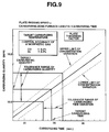
- Fig. 9 is an explaining diagram of various carburizing conditions calculated to obtained a target carburizing quantity by the algorithm of the embodiment in Fig. 6,
- Fig. 10 is an explaining diagram of various carburizing conditions calculated to obtained a target carburizing quantity under conditions wherein a plate-passing speed is set by the algorithm of the embodiment in Fig. 6,
- Fig. 11 is an explaining diagram of an example of correlation between a carburizing concentration distribution and an actually measured carburizing concentration distribution obtained in accordance with a carbon diffusion model formula by using the continuously carburizing method of metal strip in the present invention
- Fig. 12 is an explaining diagram of an example of a carburizing concentration distribution obtained in the case where an atmospheric gas composition concentration and a carburizing time are controlled by the algorithm of the embodiment of Fig. 6, Fig.
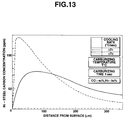
- Fig. 13 is an explaining diagram of an example of a carburizing concentration distribution obtained in the case where a cooling rate after carburizing is controlled by the algorithm of the embodiment of Fig. 6,
- Fig. 14 is an explaining diagram of a generation gas composition result and an actually measured result calculated in accordance with an atmospheric composition model formula used in an embodiment of the present invention.
- Fig. 2 shows an example of a continuous annealing and carburizing facility of a strip consisting of an extremely low carbon steel embodying the continuous carburizing method of metal strip of the present invention.
- an extremely low carbon steel strip A is plate-passed in the order of an enter side facility not shown in the figure and including a coil unwinding machine, a welding machine, a cleaning machine, etc., a preheating zone 1, a heating zone 2, a uniformly heating zone 3, a carburizing zone 4, a first cooling zone 5, a second cooling zone 6, and an exit side facility not shown and including a shearing machine, a winding machine, etc. so as to satisfy complications and history of plate temperature control as shown in Fig. 1 described in the foregoing.
- the strip A which is continuously plate-passed from the enter side facility and preheated in the preheating zone 1 is heated to a recrystallizing temperature or higher, and specifically, to a furnace temperature of 850 to 1000 °C , and the strip is heated sko that a temperature of the strip A reaches 700 to 950 °C .
- the heated strip A is held in the uniformly heating zone 3 at the recrystallizing temperature or higher for a required time, and it is possible to develop a congregated structure ⁇ 1, 1, 1 ⁇ which is advantageous to a deep drawing property.
- an upper limit value of the furnace temperature is set by a host computer not shown and described later from heat balance taking into consideration heat transfer coefficients among the radiant tubes, strip, hearth rolls, etc..
- this setting is performed together with a plate-passing speed which achieves an in-furnace time (heating time, uniformly heating time) in each heat treatment zone on the basis of a process model calculation which satisfies upper and lower limit values of a desired recrystallization temperature, an optimum route calculation which calculates an optimum time series of the plate-passing speed at a joint portion between the coils, a thermal crown calculation which calculates a maximum plate-passing speed by predicting and calculating a heat crown of the hearth rolls, or the like.
- the setting of the supply flow rate of the fuel gas into the radiant tubes is equivalent to a required (necessary) heat quantity by the furnace determined from incomings and outgoings of heat in the furnace which is obtained by adding exhaust gas lost heat and furnace body radiating heat to a heating quantity applied to the strip which brings out heat quantity from the furnace when it is plate-passed.
- This setting is made possible by the host computer not shown in accordance with control algorithm of the overall line which will be described later.
- a carburizing furnace in the carburizing zone 4 is controlled by the host computer not shown to a metal strip temperature of 700 to 950 °C , and a plate-passing speed is controlled so that the strip is passed through the carburizing furnace taking 10 to 120 seconds with the temperature of 700 °C or higher, preferably at a recrystallizing temperature or below.
- This control is performed so that a carburizing quantity (carburizing reaction rate x carburizing time) is constant with respect to a plate-passing direction of the strip, and that deviation in material characteristics is suppressed.
- the furnace temperature control is performed to avoid the problem that when the strip temperature is below 700 °C , the carburizing reaction rate is lowered and the heat treatment productivity is reduced whereas when the furnace temperature exceeds 950 °C , the material characteristics are deteriorated, and this control is performed to meet the carburizing conditions.
- composition and the supply and exhaust flow rate of carburizing gas supplied into the carburizing furnace are controlled in accordance with various conditions which are calculated by the host computer on the basis of a thermodynamics (atmospheric composition) model formula which makes free energy in the furnace minimum by considering the incomings and outgoings of materials in the furnace which will be described later.
- the composition and the supply and exhaust flow rate of carburizing gas are controlled to prevent the sooting, and at the same time, to prevent the reduction of the carburizing reaction rate and the temper color by suppressing the rise of the dew point.
- the top priority is placed on the specification factors of the strip including a carburizing concentration distribution, a carburizing depth, etc., of a carburized layer which is formed on the strip which will be described later, and the composition and the supply and exhaust flow rate of carburizing gas are calculated in view of the above-mentioned plate-passing speed and the furnace temperature.
- control variables which are the objects to be controlled in actual continuous carburizing, and by the host computer, for example, a required carburizing quantity is set from the specification factors including the carburizing concentration distribution, carburizing depth, etc., of a required carburized layer to be formed on the strip, and each control variable to achieve the carburizing quantity is calculated by suitably selecting various basic formulas relating to these preset control variables described later, and these control variables are set by considering the capability and processes of the other facilities.
- the strip is plate-passed in the carburizing furnace while moving up and down through hearth rolls 10, and in order to maintain the rolling property and roll crown of the hearth roll 10 in a predetermined state, for example, the vicinity of a bearing or the like is cooled. Furthermore, in order to maintain the strength and wear resistant property of the roll itself, chrome Cr alloy is used for the hearth roll.
- the carburizing atmospheric gas reaches the vicinity of the hearth roll, it is cooled and the sooting progresses, and thus, C diffuses into the inside of the hearth roll after C affixes to the hearth roll. When this occurs, the above-mentioned Cr and C are bonded and carbide is precipitated.
- a hearth roll chamber is separated from the carburizing atmosphere by a non-contact sealing device 11 so that the deterioration of the hearth roll is prevented.
- the inside of the hearth roll chamber is made in a slightly carburizing state to the extent that the deterioration of the hearth roll does not progress, and it was successful to prevent the so-called decarburization in which C is dissipated from the carburized surface layer portion while the strip passes through the separated hearth roll chamber.
- the inside of the hearth roll chamber may be non-carburizing atmosphere.
- a sealing layer interposed between the hearth roll chamber and the carburizing atmosphere chamber is made a three layers structure, and the above-mentioned slightly carburizing atmospheric gas is jetted into a sealing layer at the hearth roll chamber side, the above-mentioned carburizing atmospheric gas is jetted into a sealing layer at the carburizing atmosphere chamber side, and the exhaust is performed from an intermediate sealing layer.
- the jetting direction and the jet flow rate of each atmospheric gas are controlled so that the flow of each atmospheric gas is directed to the intermediate sealing layer side, and at the same time, the circulating flow generated by a plate surface gas flow caused by the plate-passing of the strip is discharged from an exhaust port formed in an end face of the sealing layer, the end face being positioned in a width direction of the strip.
- the strip A sent out from the carburizing zone 4 is plate-passed to the first cooling zone 5.
- the strip after the carburizing is rapidly cooled to a steel plate temperature of 600 °C or lower, preferably at a cooling rate of 5 °C / sec. until about 500 to 400 °C is reached.
- a flow rate, flow velocity, cooling roll angle, wrap angle, and the like of a cooling gas blown from a cooling gas jet against the strip transported into the cooling zone are controlled by the host computer.
- the strip A sent out from the cooling zone 5 is plate-passed to the second cooling zone 6.
- the gas cooling is performed until the steel plate temperature reaches 250 to 200 °C . In this manner, ultimately, it is possible to obtain a cold-rolled steel plate for extremely low carbon press forming in which the amount and form of the solid solution C in the surface layer portion is controlled.
- the temperature of the metal strip relating to the carburizing reaction is described as a carburizing temperature, however, it is apparent from the contents of the previous description that the substantial control factor is a furnace temperature.
- the carburizing quantity into the steel plate is given as preconditions to obtain target material characteristics.
- the carburizing quantity is set by integrating the distribution in a depth direction.
- the upper limit of carburizing temperature is set to a recrystallizing temperature or lower from the material characteristics conditions.
- the generation limit of the sooting can be obtained by the thermodynamics (atmospheric composition) model formula which takes into consideration the incomings and outgoings of materials, however, it is difficult to set a CO concentration and an H2 concentration related to atmospheric composition only from the condition that the sooting does not merely occur.
- a relation formula which does not disturb the carburizing reaction rate is set beforehand, and for example, using as a reference the CO concentration obtained by the atmospheric composition model formula which does not generate the sooting, the H2 concentration is calculated by using the relation formula. Specifically, it is expressed as follows.
- H2 Concentration a x (CO concentration) here, a : constant in the range of 0 ⁇ a ⁇ 5
- the constant a is set by a basic formula of a surface reaction rate described later, to a value which suppresses a production concentration of CO and H2O to a minimum, and usually it is set in a range of 0.5 to 1.0 . that is, when this relation formula is satisfied, the carburizing reaction rate based on the surface reaction rate formula becomes maximum.
- the carburizing time to achieve a desired carburizing concentration distribution is set on the basis of the above-mentioned set surface reaction rate.
- the gradient to the C concentration in the inner layer portion is to be made steep by increasing only the C concentration in the surface layer portion, it is only necessary to increase the carburizing reaction rate (enhancing the carburizing capability) and to reduce the carburizing time.
- the C concentration gradient of the inner layer portion to that of the surface layer portion is to be made gradual by increasing the whole C concentration of the steel plate, it is only necessary to increase the carburizing time by reducing the carburizing rate (lowering the carburizing capability).
- the control of these carburizing reaction rate and the carburizing time satisfies the above-mentioned restricting condition that the carburizing quantity is constant.
- an optimum plate-passing speed is set by capability calculations and process calculations of respective furnaces.
- a maximum plate-passing speed of each plate temperature control zone and a maximum plate-passing speed of the carburizing zone in the continuous annealing and carburizing facility in which the strip is plate-passed serially, it must be judged which of the plate-passing speeds governs the plate-passing speed of the whole facility. In this case, all the specification factors of the steel plate must be considered, and still the specification factors are given as absolute conditions.
- step S 20 in the carburizing zone and each plate temperature control zone, making an upper limit of the facility capability as the restricting condition, a maximum value of the plate-passing speed which satisfies heating, carburizing, and cooling specifications for each kind of steel plate is set.
- a process model formula is set from heat balance which takes into consideration the heat transfer among the radiant tubes, furnace wall, strip, hearth rolls, etc..
- a maximum value (hereinafter described as a maximum plate-passing speed) of the plate-passing speed is calculated within the range of a furnace temperature, a fuel gas supply quantity or a capacity of an electrical heating apparatus possible to be set in view of the facility, and also so that the calculated maximum value can satisfy the target plate temperature.
- an atmospheric gas composition model in the carburizing furnace which takes into consideration the incomings and outgoings of materials in the carburizing furnace is set. From this atmospheric gas composition model and the carburizing reaction rate formula, a maximum plate-passing speed which is equal to or smaller than the upper limit value of the atmospheric gas composition (specifically, CO) and which satisfies the target carburizing quantity is calculated.
- a maximum plate-passing speed which is within the range of cooling gas supply capability and which satisfies the target cooling rate / the target cooling completion temperature is calculated.
- the maximum plate-passing speed in each heat treatment zone including the carburizing zone calculated as described above is compared with each other, and a minimum value is set as the maximum plate-passing speed in the whole line.
- step S 21 by using the maximum plate-passing speed in the whole line which is set in the step S 20, in each heat treatment zone including the carburizing zone, a set value of control variables which satisfies the steel plate heating, carburizing, and cooling specifications is obtained.
- a furnace temperature which satisfies the target plate temperature is set.
- This plate temperature may be controlled by controlling the fuel gas supply flow rate or the load of the electrical heating apparatus by feedback control.
- the control of plate temperature may be performed in that on the basis of the process model calculation described previously, an optimum time series of the fuel gas supply flow rate or the load of the electrical heating apparatus which makes minimum the plate temperature variations in the joint portion of the coils of the steel plate is calculated by optimum route calculation, and based on this result, feedforward control may be performed.
- the target value includes only the carburizing quantity
- the target value of a C concentration distribution form in a thickness direction of the steel plate is designated.
- the target value of a C concentration distribution form in a thickness direction of the steel plate is designated.
- the target value of a C concentration distribution form in a thickness direction of the steel plate is designated, by using together with the atmospheric gas composition model and the carburizing reaction rate formula of the steel surface, the in-steel diffusion model considering not only the carburizing time but also the cooling period, a plate-passing speed is set again so that this plate-passing speed is within the range of the maximum plate-passing speed or smaller of the whole line set in the step S 20, and this plate-passing speed enables to set the target C concentration distribution form in a thickness direction of the steel plate.
- an atmospheric gas composition which satisfies the target carburizing quantity is calculated.
- the plate-passing speed which is set again is set as a plate-passing speed of the whole line in steps following the present step.
- the logic of the plate-passing speed setting to make the C concentration distribution form in a thickness direction of the steel plate satisfy the target value in the step S 21, however, in order to prevent the set plate-passing speed from being changed and set again due to other causes, the setting of the plate-passing speed which satisfies the C concentration distribution form in a thickness direction of the steel plate is preferable to perform in step S 23.
- it is performed in step S 23.
- the flow velocity of the cooling gas jet is set by the number of revolutions of a fan, or the like so as to satisfy the target cooling rate and the target cooling completion time.
- step S 22 heat crown of the hearth rolls in each heat treatment zone including the carburizing zone is predicted and calculated by a plate temperature model and a heat balance model of a roll chamber, and a maximum plate-passing speed which falls within the jetting generation limit and the buckling generation limit of the strip is calculated, that is, a so-called thermal crown calculation is performed.
- the maximum plate-passing speed calculated here is larger than the maximum plate-passing speed of the whole line which is set in the steps up to the step S 21, goes to the next step S 23.
- the maximum plate-passing speed calculated here is smaller than the maximum plate-passing speed of the whole line which is set in the steps up to the step S 21, the maximum plate-passing speed obtained in this thermal crown calculation is set again as a plate-passing speed of the whole line, and moves to the above-mentioned step SS 21.
- step 23 when a plate-passing speed which is the target is designated beforehand by the reasons of operation such as welding work of a joint portion of the coils, coil inspection, and the like, or some other reasons (mainly troubles), after checking that the designated plate-passing speed is equal to or smaller than the maximum plate-passing speed of the whole line which is set in the steps S 20 to S 22, the plate-passing speed of the whole line is set to the designated plate-passing speed.
- step S 24 with respect to the ultimately set plate-passing speed of the whole line, control variables which satisfy the steel plate heating, carburizing, and cooling specifications in each heat treatment zone including the carburizing zone are calculated, and are set.
- the contents of the calculation are similar to that in the step S 21, however, the setting and calculation of the plate-passing speed based on the C concentration distribution form in the depth direction of the steel plate are not performed.
- the plate temperature control in the carburizing zone 4 may be considered to be the same contents as the plate temperature control in the heating zone 2 and uniformly heating zone 3.
- the conventional carburizing technique is carried out for the purpose of surface hardening to improve the wear resistant property and anti-impulse property of a discontinuous article consisting of a so-called thermally refined steel such as a gear, shaft, bearing, etc.
- the C content in a raw material is 0.05 % or larger
- the required carburizing quantity is 0.1 % or more
- the carburizing depth is 0.5 to 1.5 mm or larger.
- the needed time for carburizing is as long as 1 to 5 hours. Under such conditions, the C concentration in the steel plate surface layer portion has reached the equilibrium concentration with respect to time, and hence the carburizing rate is in an in-steel diffusion-governing area as shown in Fig.
- the strip is a discontinuous article consisting of the extremely low carbon steel, and it is performed for the purpose of improving the surface characteristics of the strip and improving the material characteristics of the steel plate itself.
- the carburizing conditions of the metal strip are obtained from the specifications (Japanese Patent Laid-Open Publication Hei No. 3-199344, etc.) required for metal which is intended to improve the anti-secondary working brittleness
- the C content in the raw material is 200 ppm or less
- the carburizing depth is 50 to 200 ⁇ m
- the carburizing time dependent on the plate-passing speed is 120 seconds or less.
- the carburizing rate is in a surface reaction-governing area as shown in Fig. 3 wherein the carburizing rate follows the reaction rate in the steel surface, and the carburizing rate is proportional to time itself.
- the plate-passing speed is set from the plate temperature control which is performed in heat sections other than the carburizing zone, and also in many cases the plate-passing speed having the most fast response from various operation conditions is controlled.
- carburizing conditions are set from the specification factors of the steel plate required under the above-mentioned plate-passing speed so that the set carburizing conditions satisfy the carburizing quantity.
- the atmospheric gas composition in carburizing condition can be obtained from chemical equilibrium.
- conceivable reactions are all listed, and the gas composition is obtained by solving non-linear simultaneous equations from the equilibrium relationships of the reactions.
- thermodynamics (atmospheric composition) model formula is conceived as described below, and the atmospheric gas composition which prevents the sooting generation is obtained.
- the free energy f g i of i th kind of gas relating to the gas product is expressed by the following equations 2 to 4 supposing that the number of moles of the kind of gas is x g i with respect to free energy C g i of i th kind of gas.
- a c ij the number of atoms of j th element contained in a molecule of i th kind of condensation
- b j the quantity of j th element existing in the system
- m the number of kinds of elements existing in the system.
- a linearized atmospheric composition model formula is set from the equations 8 and 1 by a program stored in the host computer, and the solutions obtained from the atmospheric composition model formula are converged to obtain an optimum solution.
- the C balance in the furnace is given by the following equations 9 and 10.
- the equation 10 is a function which is calculated from the specification factors and the surface reaction rate.
- W l g W c s + W o g (9)
- W c s ⁇ (V, t, w, LS)) (10)
- W g i C mass in the atmospheric gas entered into the furnace
- W g c C mass brought out by the strip
- W g o C mass in the atmospheric gas exits from the furnace
- V surface reaction rate
- t carburizing time
- w plate width.
- thermodynamics (atmosphere composition) model formula which takes into consideration the incomings and outgoings of materials in the actual continuous carburizing in the carburizing furnace, it becomes possible to enhance the carburizing capability of the atmosphere composition as compared with the atmospheric factors which are obtained without considering the incomings and outgoings of materials in the furnace, while preventing the generation of sooting with certainty. Accordingly, it is possible to improve the actual operation capability in which, for example, the plate-passing speed is increased by increasing the CO concentration in the atmospheric gas.
- the carburizing reaction is disturbed by the reaction represented by the following equations 18 and 19.
- the surface reaction rate V is represented by the following equation 20 or 21.
- reaction rate constants k1 and k2 can be set by the following equation 22.
- k i A i ⁇ exp ( - E i /RT) (22) where, Ai : frequency factor, Ei : activation energy, R : gas constant, and T : absolute temperature.
- reaction rate constants k1 and k2 are calculated from experimental values under the conditions of various absolute temperatures T.
- Fig. 5 shows reaction rate constant k1 obtained by experiments.
- the equation 14 may be used as a surface reaction rate formula.
- the diffusion coefficient D is set also by Arrhenius's formula represented by the following equation 24, in the embodiment, it is represented approximately by actual measurement data.
- D exp (a ⁇ T ⁇ 1 + b) (24) where, T : carburizing temperature, a : proportional coefficient, and b : constant.
- the carburizing quantity into the steel plate can be calculated by the equation 17 or 21 or 22 and 23. This means that under the condition that the carburizing quantity is constant, if a carburizing concentration at one point of a desired carburizing concentration distribution is set, then the above-mentioned carbon diffusion model formula will be set, and even when the carburizing quantity is differrent, if carburizing concentrations at two points or more of the desired carburizing concentration distribution are set, then the above-mentioned carbon diffusion model formula will be set.
- Fig. 6 shows a flowchart of algorithm for setting a carburizing condition in which the above-described calculations are sequentially performed by a program stored beforehand in the host computer, and under this carburizing condition, the specification factor of the steel plate after carburizing, that is, the carburizing quantity into the strip which is given from a desired carburizing concentration distribution in the embodiment coincides with the carburizing quantity into the strip calculated from a decreased quantity of C in the atmospheric gas.
- step S 1 from the set conditions which is given as steel plate specification factors after carburizing, such conditions as an atmospheric gas composition, flow rate of supplied gas, carburizing temperature and plate-passing speed are read, and from the steel plate factor and carburizing concentration distribution, such condition as a C concentration C1 at a designated depth X1 from the steel plate surface is read.
- the plate-passing speed is represented by LS, and this is a parameter which is modified in subsequently performed flow.
- step S 2 a carburizing quantity ⁇ C into the steel plate is set from the steel plate factors and the steel plate specification, and a C quantity per unit time which is brought out by the strip from the carburizing furnace is calculated.
- step S 3 the atmospheric composition model formula mentioned above is set from the composition of atmospheric gas which was read in the step S 1.
- step S 4 in accordance with the atmospheric composition model formula set in the step S 3, each component concentration of the atmospheric gas taking into consideration the C quantity brought out by the strip from the carburizing furnace is calculated.
- step S 5 on the basis of the equation 17, a surface reaction rate of the steel plate is calculated.
- step S 6 on the basis of the equation 23, a carburizing rate into the steel is calculated, and a C diffusion quantity into the steel is calculated.
- step S 7 when the carburizing treatment time is elapsed, goes to step S 7, and the surface reaction rate or the diffused C quantity per unit time and unit area calculated in the step S 5 or step S 6 is integrated by the treatment time and the steel plate total surface area, and a carburizing quantity ⁇ C' into the steel plate is calculated.
- step S 8 the absolute value of a difference between the set carburizing quantity ⁇ C and the carburizing quantity ⁇ C' obtained as a result of the calculation is judged whether it is smaller than a predetermined value a or not, and when the absolute value of the difference is smaller than the predetermined value a, goes to step S 10, and if not, goes to step S 9.
- step S 9 on the basis on the above-mentioned carburizing quantity, the set carburizing quantity is corrected based on the following equation 25, and goes to the step S 3.
- ⁇ C ⁇ C + ( ⁇ C' - ⁇ C) x b (25) where, b : constant.
- step S 10 when the total C quantity brought out by the step from the carburizing furnace and the total C quantity carburized are equal to each other, that is, when the incomings and outgoings of materials within the carburizing furnace are satisfied, goes to step S 10.
- step S 10 the absolute value of a difference between the target carburizing quantity ⁇ C o and the set carburizing quantity ⁇ C is judged whether it is smaller than a predetermined value d or not, and when the absolute value of the difference is smaller than the predetermined value d, goes to step S 12, and if not, goes to step S 11.
- step S 11 in order to obtain the set carburizing quantity set from the carburizing concentration distribution condition, any one or more of the parameters of the atmospheric gas flow rate, atmospheric composition, plate-passing speed, and carburizing temperature, and goes to the step S 2.
- the plate-passing speed LS is corrected in order to correct the difference between the predetermined carburizing quantity ⁇ C o and the set carburizing quantity ⁇ C , it is only necessary to calculate, for example, based on the following equation 26 the plate-passing speed LS which is to be corrected.
- LS LS + ( ⁇ C - ⁇ C0 ) x d' (26) where, d' : constant.
- step S 12 in accordance with the in-steel diffusion model set in the step S 6, a C concentration C'1 at the designated depth X1 from the steel plate surface is calculated.
- step S 13 it is judged whether the absolute value of a difference between the set C concentration C1 at the designated depth X1 from the steel plate surface read in the step S 1 and the C concentration C'1 at the designated depth X1 from the steel plate surface calculated in the step S 12 is smaller than a predetermined value e or not, and when the absolute value of the difference is smaller than the predetermined value, goes to step S 15, and if not, goes to step S 14.
- step S 14 in order to obtain the set carburizing quantity which is set from the carburizing concentration distribution condition, any one or more parameters of the atmospheric composition, plate-passing speed, and carburizing temperature are changed, and goes to the step S 2.
- each set value of the concentration of atmospheric gas component or the plate-passing speed, or the carburizing temperature obtained as a result of the above calculation is outputted in accordance with the object of the control, and at the same time, the calculation results such as the total carburizing quantity, mean carburizing quantity, carburizing distribution, etc., are outputted, and the program is completed.
- the atmospheric gas flow rate in the input conditions is a control variable for changing the CO2 and H2O concentrations in the atmospheric gas as described previously, and as the control factors, the atmospheric composition is intended to be included therein similar to the CO + H2 flow rate which is supplied into the furnace.
- the broken line shows a dew point upper limit.
- the long and short dash line shows sooting generation limit obtained without taking into consideration the incomings and outgoings of materials.
- the hatched portion shows an operation range in the actual carburizing operation.
- Fig. 8 shows the correlation between the carburizing quantity in the case where each carburizing condition calculated by the program, that is, each control variable is changed, and the actually measured carburizing quantity.
- the calculated carburizing quantity and the actually measured value coincident with each other to a great extent.
- the setting of the carburizing rate, that is, the surface reaction rate, and the setting of its temperature dependency coefficient are correct, and also means that, as far as the setting of the surface reaction rate is correct, the continuous carburizing method of the present embodiment can be applied to a wide range of area in which the carburizing rate follows the surface reaction rate which is larger than the diffusion rate.
- the predetermined (target) carburizing quantity was set in the step S 2 as apparently shown in Fig. 9, and at the same time, the tolerance range to the plate thickness was set. Also, in the step S 1, the target carburizing temperature was set from the material condition of the steel plate.
- the CO concentration and H2 concentration are set as the atmospheric gas condition to prevent sooting.
- plate-passing speed carburizing zone furnace length / carburizing tim e
- the target plate-passing speed and its tolerance range are set and outputted.
- the carburizing time (plate-passing speed) is set.
- the predetermined (target) carburizing quantity is set.
- the target carburizing temperature was set from the material characteristic condition of the steel plate.
- the carburizing time is calculated by dividing the effective carburizing furnace length by the plate-passing speed.
- the upper limits of the CO concentration and H2 concentration are set as the atmospheric gas condition for preventing sooting.
- the surface reaction rate formula and the in-steel diffusion model formula are set, and from these formulas, the CO concentration, H2 concentration, CO2 concentration, and H2 O concentration which are required to achieve the target carburizing quantity are set.
- the atmospheric gas composition when the target carburizing quantity is increased or the carburizing time is decreased, the atmospheric gas composition is controlled, for example, so that the CO concentration in the atmospheric gas is increased, whereas when the target carburizing quantity is decreased or the carburizing time is increased, the atmospheric gas composition is controlled, for example, so that the CO concentration in the atmospheric gas is decreased.
- the ratio of the CO flow rate and the H2 flow rate in the atmospheric gas flow rate supplied to the carburizing furnace may be changed, and as to the CO2 and H2O concentrations, the total flow rate of the atmospheric gas may be changed.
- the carburizing concentration distribution desired for the carburized thin steel plate is calculated by the carbon diffusion model formula based on the Fick's law.
- the carburizing quantity per unit area is set by integrating the carburizing concentration distribution in the depth direction, and the carbon diffusion model formula is set from a desired carburizing concentration distribution under a restriction condition which satisfies the carburizing quantity.
- a tolerance range is set for a target value at each point in the depth direction, and the carburizing temperature and the carburizing time which are parameters of the model formula are set so that a carburizing concentration profile calculated from the carbon diffusion model formula falls within the tolerance range.
- the carburizing concentration in order to acquire the peak point of the carburizing concentration, it is desired to set the carburizing concentration at one point in the range of the depth of 10 to 50 ⁇ m, and at one point or more in the range of 100 to 250 ⁇ m.
- the carburizing quantity is constant, if the carburizing concentration is set at only one point under the condition in which various conditions such as surface reaction rate and carburizing temperature, carburizing time, and the like, are set, the carbon diffusion model formula will be set directly or uniquely.
- Fig. 12 the results of experiments of the influence of the carburizing time in the in-steel diffusion model formula are shown in Fig. 12.
- the experiments are conducted under the condition that the carburizing temperature T °C is constant, and the total carburizing quantity ⁇ C ppm is constant, and the solid line indicates the case wherein the carburizing is performed under the atmospheric condition that the CO concentration (%) is a4 , the H2 concentration (%) is b4 , and the carburizing time (treatment time, sec.) is t4 , and the broken line indicates the case wherein the carburizing is performed under the atmospheric condition that the CO concentration (%) is a5 , the H2 concentration (%) is b5 , and the carburizing time (treatment time, sec.) is t5 .
- the carburizing time t5 3 t4 , the CO concentration a4 > a5 , and the H2 concentration b4 >> b5 .
- the higher the CO concentration and the H2 concentration the larger becomes the carburizing reaction rate, and the longer the carburizing time, the larger becomes the carburizing quantity into the inner layer portion.
- Fig. 13 Under the condition that the carburizing temperature T °C constant, the carburizing time t sec. constant, the CO concentration a6 % constant, and the H2 concentration b6 % constant, the solid line shows the case where the cooling is performed at a cooling rate of ⁇ T1 °C/sec., and the broken line shows the case where the cooling is performed at a cooling rate of ⁇ T2 °C/sec., and the cooling rates are in the following relation: ⁇ T1 ⁇ ⁇ T2 .
- the carburizing time (plate-passing speed) and the atmospheric gas composition are ultimately changed in order to obtain a predetermined carburizing concentration distribution in the steel plate depth direction and a predetermined carburizing quantity; and as to the case wherein, by using the algorithm of Fig. 6, under the condition that the carburizing time is determined based on the plate-passing speed set from the operation condition other than the carburizing treatment and the carburizing temperature is set from the material characteristic condition, the atmospheric gas composition is ultimately changed in order to obtain a predetermined C quantity.
- the following control factors are also considered.
- control factors are not limited to any one of the above items, and all the items can be applied to any case.
- the surface reaction rate is calculated taking into consideration the influence of CO, H2, CO2, and H2O, however, as described in the foregoing, the surface reaction rate may be calculated by considering the influence of bi-carbon hydride.
- the equilibrium state is calculated by linearizing the thermodynamics model formula which takes into consideration the incomings and outgoings of materials, and by converging its solutions.
- the calculating means is not limited to the above means.
- the embodiment is described in detail only as to the case where in particular, in the surface reaction-governing area, the strip consisting of the extremely low carbon steel is continuously carburized and annealed, however, the embodiment is applicable to other carburizing reaction-governing area, or the case where only the carburizing is needed, or the other metal strips.
Landscapes
- Chemical & Material Sciences (AREA)
- Chemical Kinetics & Catalysis (AREA)
- Engineering & Computer Science (AREA)
- Materials Engineering (AREA)
- Mechanical Engineering (AREA)
- Metallurgy (AREA)
- Organic Chemistry (AREA)
- Solid-Phase Diffusion Into Metallic Material Surfaces (AREA)
- Heat Treatment Of Strip Materials And Filament Materials (AREA)
Applications Claiming Priority (9)
| Application Number | Priority Date | Filing Date | Title |
|---|---|---|---|
| JP277305/92 | 1992-10-15 | ||
| JP27730592 | 1992-10-15 | ||
| JP28752492 | 1992-10-26 | ||
| JP287523/92 | 1992-10-26 | ||
| JP287524/92 | 1992-10-26 | ||
| JP28752392 | 1992-10-26 | ||
| JP344472/92 | 1992-12-24 | ||
| JP34447292 | 1992-12-24 | ||
| PCT/JP1993/001486 WO1994009175A1 (fr) | 1992-10-15 | 1993-10-15 | Procede permettant de cementer en continu un feuillard |
Publications (3)
| Publication Number | Publication Date |
|---|---|
| EP0626467A1 true EP0626467A1 (de) | 1994-11-30 |
| EP0626467A4 EP0626467A4 (de) | 1995-03-01 |
| EP0626467B1 EP0626467B1 (de) | 1997-05-21 |
Family
ID=27479120
Family Applications (1)
| Application Number | Title | Priority Date | Filing Date |
|---|---|---|---|
| EP93922640A Expired - Lifetime EP0626467B1 (de) | 1992-10-15 | 1993-10-15 | Verfahren zur kontinuierlichen aufkohlung eines stahlbandes |
Country Status (5)
| Country | Link |
|---|---|
| EP (1) | EP0626467B1 (de) |
| KR (1) | KR100266037B1 (de) |
| CA (1) | CA2125785A1 (de) |
| DE (1) | DE69310897T2 (de) |
| WO (1) | WO1994009175A1 (de) |
Cited By (3)
| Publication number | Priority date | Publication date | Assignee | Title |
|---|---|---|---|---|
| AT404029B (de) * | 1996-09-16 | 1998-07-27 | Ald Aichelin Ges M B H | Niederdruck-aufkohlungsanlage |
| WO1998054371A1 (fr) * | 1997-05-27 | 1998-12-03 | Centre De Recherches Metallurgiques | Procede de fabrication en continu d'une bande en acier pour emboutissage presentant des proprietes de surface ameliorees |
| EP1484419A3 (de) * | 2003-06-05 | 2005-10-19 | ThyssenKrupp Stahl AG | Verfahren zum Herstellen von aufgekohlten Stahlbändern |
Families Citing this family (8)
| Publication number | Priority date | Publication date | Assignee | Title |
|---|---|---|---|---|
| EP1224296A1 (de) | 1999-10-29 | 2002-07-24 | Basf Aktiengesellschaft | L-pantolacton-hydrolase und ein verfahren zur herstellung von d-pantolacton |
| DE102005030433B3 (de) * | 2005-06-30 | 2006-12-07 | Ab Skf | Verfahren zum Aufkohlen eines Eisenwerkstoffs |
| KR101166919B1 (ko) * | 2010-02-08 | 2012-07-23 | 한국생산기술연구원 | 침탄깊이 실시간 모니터링방법 |
| DE102010039941B4 (de) * | 2010-08-30 | 2012-05-16 | Aktiebolaget Skf | Verfahren zum Aufkohlen eines Eisenwerkstoffes |
| KR102094791B1 (ko) * | 2018-12-20 | 2020-03-30 | (주)비전테크놀러지 | 차량용 스털링 앵글센서의 실드코어 및 그 제조방법 |
| RU2723397C1 (ru) * | 2020-02-13 | 2020-06-11 | Общество с ограниченной ответственностью Управляющая компания "Алтайский завод прецизионных изделий" | Способ цементации |
| WO2024090229A1 (ja) * | 2022-10-27 | 2024-05-02 | 山陽特殊製鋼株式会社 | 炭素濃度分布の解析方法 |
| JP7595701B2 (ja) * | 2022-10-27 | 2024-12-06 | 山陽特殊製鋼株式会社 | 炭素濃度分布の解析方法 |
Family Cites Families (14)
| Publication number | Priority date | Publication date | Assignee | Title |
|---|---|---|---|---|
| DE1934145B2 (de) * | 1969-07-05 | 1973-12-13 | Hartmann & Braun Ag, 6000 Frankfurt | Verfahren zur Gewinnung eines An zeige und Regelsignales fur das Kohlen Stoffpotential bei der Gasaufkohlung von Stahl |
| DE1942281B2 (de) * | 1969-08-20 | 1973-12-13 | Hartmann & Braun Ag, 6000 Frankfurt | Verfahren zur Gewinnung eines An zeige und Regelsignales fur das Kohlen Stoffpotential bei der Gasaufkohlung von Stahl |
| DE2152439C3 (de) * | 1971-10-21 | 1978-04-27 | Brown, Boveri & Cie Ag, 6800 Mannheim | Verfahren und Einrichtung zur Verhinderung der Rußbildung in Aufkohlungsräumen |
| DE2152440C3 (de) * | 1971-10-21 | 1979-04-12 | Brown, Boveri & Cie Ag, 6800 Mannheim | Verfahren und Anordnung zum rußfreien Aufkohlen von Stahl |
| US3950192A (en) * | 1974-10-30 | 1976-04-13 | Monsanto Company | Continuous carburizing method |
| DE2835444C2 (de) * | 1978-08-12 | 1985-08-01 | Ruhrgas Ag, 4300 Essen | Verfahren zur Gewinnung eines Anzeige- und Regelsignals für den Kohlenstoffpegel bei der Gasaufkohlung von Eisenteilen |
| DE3139622C2 (de) * | 1981-10-06 | 1989-12-14 | Joachim Dr.-Ing. 7250 Leonberg Wünning | Verfahren zur Gasaufkohlung von Stahl und Vorrichtung zu seiner Durchführung |
| JPS58144469A (ja) * | 1982-02-22 | 1983-08-27 | Aisin Seiki Co Ltd | 浸炭炉のプログラム制御装置 |
| WO1992005295A1 (fr) * | 1986-08-12 | 1992-04-02 | Nobuo Nishioka | Procede et appareil de cementation au gaz |
| JP3021458B2 (ja) * | 1987-12-28 | 2000-03-15 | 同和鉱業株式会社 | ガス浸炭熱処理方法 |
| JP2954339B2 (ja) * | 1990-11-30 | 1999-09-27 | 川崎製鉄株式会社 | 連続焼鈍炉 |
| JPH04107256A (ja) * | 1990-08-28 | 1992-04-08 | Nippon Seiko Kk | 浸炭炉 |
| JPH04198462A (ja) * | 1990-11-28 | 1992-07-17 | Komatsu Ltd | 浸炭装置 |
| JPH04202648A (ja) * | 1990-11-30 | 1992-07-23 | Kawasaki Steel Corp | 連続浸炭炉における浸炭性雰囲気ガスの供給方法 |
-
1993
- 1993-10-15 CA CA 2125785 patent/CA2125785A1/en not_active Abandoned
- 1993-10-15 WO PCT/JP1993/001486 patent/WO1994009175A1/ja not_active Ceased
- 1993-10-15 EP EP93922640A patent/EP0626467B1/de not_active Expired - Lifetime
- 1993-10-15 KR KR1019940702014A patent/KR100266037B1/ko not_active Expired - Fee Related
- 1993-10-15 DE DE69310897T patent/DE69310897T2/de not_active Expired - Fee Related
Cited By (4)
| Publication number | Priority date | Publication date | Assignee | Title |
|---|---|---|---|---|
| AT404029B (de) * | 1996-09-16 | 1998-07-27 | Ald Aichelin Ges M B H | Niederdruck-aufkohlungsanlage |
| WO1998054371A1 (fr) * | 1997-05-27 | 1998-12-03 | Centre De Recherches Metallurgiques | Procede de fabrication en continu d'une bande en acier pour emboutissage presentant des proprietes de surface ameliorees |
| BE1011178A3 (fr) * | 1997-05-27 | 1999-06-01 | Metallurigiques Ct Voor Resear | Procede de fabrication en continu d'une bande en acier pour emboutissage presentant des proprietes de surface ameliorees. |
| EP1484419A3 (de) * | 2003-06-05 | 2005-10-19 | ThyssenKrupp Stahl AG | Verfahren zum Herstellen von aufgekohlten Stahlbändern |
Also Published As
| Publication number | Publication date |
|---|---|
| WO1994009175A1 (fr) | 1994-04-28 |
| KR100266037B1 (ko) | 2000-09-15 |
| EP0626467A4 (de) | 1995-03-01 |
| EP0626467B1 (de) | 1997-05-21 |
| DE69310897D1 (de) | 1997-06-26 |
| CA2125785A1 (en) | 1994-04-28 |
| DE69310897T2 (de) | 1998-01-08 |
Similar Documents
| Publication | Publication Date | Title |
|---|---|---|
| EP0626467B1 (de) | Verfahren zur kontinuierlichen aufkohlung eines stahlbandes | |
| JP2001507080A (ja) | アンモニアとの反応により強化された高強度深絞り用鋼 | |
| RU2727385C1 (ru) | Способ динамического подстраивания для изготовления термообработанной листовой стали | |
| KR20190087496A (ko) | 열적 처리된 강판의 제조를 위한 동적 조정 방법 | |
| US6074493A (en) | Method of continuously carburizing metal strip | |
| JPS6346144B2 (de) | ||
| US11414736B2 (en) | Production method of hot-dip galvanized steel sheet | |
| Primavera et al. | Influence of process parameters on scale reduction with H2 | |
| JP2944755B2 (ja) | 金属帯の連続浸炭方法 | |
| JP2021147648A (ja) | 冷延鋼板および溶融亜鉛めっき鋼板の製造方法 | |
| JP3028995B2 (ja) | 金属帯の連続浸炭及び板温制御方法 | |
| JP2938292B2 (ja) | 金属帯の連続浸炭方法 | |
| US6955730B2 (en) | Method for enhancing the metallurigcal quality of products treated in a furnace | |
| US12291757B2 (en) | Method for the heat treatment of a metal based on a predicted austenite content to achieve austenite content within a quality window | |
| JPH06192815A (ja) | 金属帯の連続浸炭設備 | |
| JP2025095269A (ja) | 鋼板製造設備の制御方法および鋼板製造設備 | |
| JPH11158559A (ja) | 連続焼鈍炉の炉内雰囲気制御方法 | |
| JP2983366B2 (ja) | 連続焼鈍炉における浸炭浸窒処理設備 | |
| JP2983398B2 (ja) | 金属帯の連続焼鈍及び連続浸炭方法 | |
| JP3849559B2 (ja) | 高強度冷延鋼板の製造方法 | |
| JP2005133158A (ja) | 脱炭層深さ予測方法、脱炭層深さ制御方法及び鋼材の圧延方法 | |
| EP3168314A1 (de) | Verfahren zur wärmebehandlung metallischer werkstücke | |
| JPWO1994009175A1 (ja) | 金属帯の連続浸炭方法 | |
| JPH026810B2 (de) | ||
| Rowan et al. | Gas Carburizing |
Legal Events
| Date | Code | Title | Description |
|---|---|---|---|
| PUAI | Public reference made under article 153(3) epc to a published international application that has entered the european phase |
Free format text: ORIGINAL CODE: 0009012 |
|
| 17P | Request for examination filed |
Effective date: 19940707 |
|
| AK | Designated contracting states |
Kind code of ref document: A1 Designated state(s): DE FR GB |
|
| A4 | Supplementary search report drawn up and despatched | ||
| AK | Designated contracting states |
Kind code of ref document: A4 Designated state(s): DE FR GB |
|
| 17Q | First examination report despatched |
Effective date: 19950731 |
|
| GRAG | Despatch of communication of intention to grant |
Free format text: ORIGINAL CODE: EPIDOS AGRA |
|
| GRAH | Despatch of communication of intention to grant a patent |
Free format text: ORIGINAL CODE: EPIDOS IGRA |
|
| GRAH | Despatch of communication of intention to grant a patent |
Free format text: ORIGINAL CODE: EPIDOS IGRA |
|
| GRAA | (expected) grant |
Free format text: ORIGINAL CODE: 0009210 |
|
| AK | Designated contracting states |
Kind code of ref document: B1 Designated state(s): DE FR GB |
|
| REF | Corresponds to: |
Ref document number: 69310897 Country of ref document: DE Date of ref document: 19970626 |
|
| ET | Fr: translation filed | ||
| PLBE | No opposition filed within time limit |
Free format text: ORIGINAL CODE: 0009261 |
|
| STAA | Information on the status of an ep patent application or granted ep patent |
Free format text: STATUS: NO OPPOSITION FILED WITHIN TIME LIMIT |
|
| 26N | No opposition filed | ||
| REG | Reference to a national code |
Ref country code: GB Ref legal event code: IF02 |
|
| PGFP | Annual fee paid to national office [announced via postgrant information from national office to epo] |
Ref country code: DE Payment date: 20071011 Year of fee payment: 15 |
|
| PGFP | Annual fee paid to national office [announced via postgrant information from national office to epo] |
Ref country code: GB Payment date: 20071010 Year of fee payment: 15 Ref country code: FR Payment date: 20071009 Year of fee payment: 15 |
|
| GBPC | Gb: european patent ceased through non-payment of renewal fee |
Effective date: 20081015 |
|
| REG | Reference to a national code |
Ref country code: FR Ref legal event code: ST Effective date: 20090630 |
|
| PG25 | Lapsed in a contracting state [announced via postgrant information from national office to epo] |
Ref country code: DE Free format text: LAPSE BECAUSE OF NON-PAYMENT OF DUE FEES Effective date: 20090501 |
|
| PG25 | Lapsed in a contracting state [announced via postgrant information from national office to epo] |
Ref country code: FR Free format text: LAPSE BECAUSE OF NON-PAYMENT OF DUE FEES Effective date: 20081031 |
|
| PG25 | Lapsed in a contracting state [announced via postgrant information from national office to epo] |
Ref country code: GB Free format text: LAPSE BECAUSE OF NON-PAYMENT OF DUE FEES Effective date: 20081015 |