EP0626514A1 - Brennstoffvorwärmvorrichtung mit veränderbarer Brennstoffeinspritzung - Google Patents
Brennstoffvorwärmvorrichtung mit veränderbarer Brennstoffeinspritzung Download PDFInfo
- Publication number
- EP0626514A1 EP0626514A1 EP94303802A EP94303802A EP0626514A1 EP 0626514 A1 EP0626514 A1 EP 0626514A1 EP 94303802 A EP94303802 A EP 94303802A EP 94303802 A EP94303802 A EP 94303802A EP 0626514 A1 EP0626514 A1 EP 0626514A1
- Authority
- EP
- European Patent Office
- Prior art keywords
- fuel
- gas
- engine
- heater
- stream
- Prior art date
- Legal status (The legal status is an assumption and is not a legal conclusion. Google has not performed a legal analysis and makes no representation as to the accuracy of the status listed.)
- Withdrawn
Links
- 239000000446 fuel Substances 0.000 title claims abstract description 144
- 238000002347 injection Methods 0.000 title claims description 37
- 239000007924 injection Substances 0.000 title claims description 37
- 238000002485 combustion reaction Methods 0.000 claims abstract description 41
- 238000010438 heat treatment Methods 0.000 claims abstract description 28
- 230000004044 response Effects 0.000 claims description 3
- 239000003502 gasoline Substances 0.000 description 51
- 239000007789 gas Substances 0.000 description 45
- 230000006698 induction Effects 0.000 description 17
- 230000000694 effects Effects 0.000 description 7
- XLYOFNOQVPJJNP-UHFFFAOYSA-N water Substances O XLYOFNOQVPJJNP-UHFFFAOYSA-N 0.000 description 7
- 239000000498 cooling water Substances 0.000 description 6
- 239000012212 insulator Substances 0.000 description 6
- QVGXLLKOCUKJST-UHFFFAOYSA-N atomic oxygen Chemical compound [O] QVGXLLKOCUKJST-UHFFFAOYSA-N 0.000 description 4
- 230000008859 change Effects 0.000 description 4
- 239000012530 fluid Substances 0.000 description 4
- 239000001301 oxygen Substances 0.000 description 4
- 229910052760 oxygen Inorganic materials 0.000 description 4
- 230000006835 compression Effects 0.000 description 3
- 238000007906 compression Methods 0.000 description 3
- 238000010276 construction Methods 0.000 description 3
- 238000010586 diagram Methods 0.000 description 3
- 239000002828 fuel tank Substances 0.000 description 3
- 239000007788 liquid Substances 0.000 description 3
- 230000007246 mechanism Effects 0.000 description 3
- 229910000838 Al alloy Inorganic materials 0.000 description 2
- 230000001133 acceleration Effects 0.000 description 2
- 230000002411 adverse Effects 0.000 description 2
- 238000000889 atomisation Methods 0.000 description 2
- 230000008901 benefit Effects 0.000 description 2
- 230000001276 controlling effect Effects 0.000 description 2
- 238000001816 cooling Methods 0.000 description 2
- 238000013461 design Methods 0.000 description 2
- 229930195733 hydrocarbon Natural products 0.000 description 2
- 150000002430 hydrocarbons Chemical class 0.000 description 2
- 238000009434 installation Methods 0.000 description 2
- 230000001788 irregular Effects 0.000 description 2
- 238000000034 method Methods 0.000 description 2
- 230000002093 peripheral effect Effects 0.000 description 2
- 230000001105 regulatory effect Effects 0.000 description 2
- 241000276425 Xiphophorus maculatus Species 0.000 description 1
- 230000009471 action Effects 0.000 description 1
- 239000000853 adhesive Substances 0.000 description 1
- 230000001070 adhesive effect Effects 0.000 description 1
- 229910002113 barium titanate Inorganic materials 0.000 description 1
- JRPBQTZRNDNNOP-UHFFFAOYSA-N barium titanate Chemical compound [Ba+2].[Ba+2].[O-][Ti]([O-])([O-])[O-] JRPBQTZRNDNNOP-UHFFFAOYSA-N 0.000 description 1
- 239000000919 ceramic Substances 0.000 description 1
- 229910010293 ceramic material Inorganic materials 0.000 description 1
- 238000009833 condensation Methods 0.000 description 1
- 230000005494 condensation Effects 0.000 description 1
- 230000006866 deterioration Effects 0.000 description 1
- 230000005611 electricity Effects 0.000 description 1
- 230000003028 elevating effect Effects 0.000 description 1
- 239000003822 epoxy resin Substances 0.000 description 1
- 238000001704 evaporation Methods 0.000 description 1
- 238000002474 experimental method Methods 0.000 description 1
- 238000004880 explosion Methods 0.000 description 1
- 238000010304 firing Methods 0.000 description 1
- 239000011261 inert gas Substances 0.000 description 1
- 239000010687 lubricating oil Substances 0.000 description 1
- 238000004519 manufacturing process Methods 0.000 description 1
- 239000000463 material Substances 0.000 description 1
- 238000002156 mixing Methods 0.000 description 1
- 238000012986 modification Methods 0.000 description 1
- 230000004048 modification Effects 0.000 description 1
- 239000003921 oil Substances 0.000 description 1
- 238000013021 overheating Methods 0.000 description 1
- 238000012856 packing Methods 0.000 description 1
- 239000002245 particle Substances 0.000 description 1
- 239000005011 phenolic resin Substances 0.000 description 1
- 239000011347 resin Substances 0.000 description 1
- 229920005989 resin Polymers 0.000 description 1
- 238000007790 scraping Methods 0.000 description 1
- 238000005507 spraying Methods 0.000 description 1
- 238000012360 testing method Methods 0.000 description 1
- 238000012546 transfer Methods 0.000 description 1
- 238000011144 upstream manufacturing Methods 0.000 description 1
- 238000010792 warming Methods 0.000 description 1
Images







Classifications
-
- F—MECHANICAL ENGINEERING; LIGHTING; HEATING; WEAPONS; BLASTING
- F02—COMBUSTION ENGINES; HOT-GAS OR COMBUSTION-PRODUCT ENGINE PLANTS
- F02M—SUPPLYING COMBUSTION ENGINES IN GENERAL WITH COMBUSTIBLE MIXTURES OR CONSTITUENTS THEREOF
- F02M31/00—Apparatus for thermally treating combustion-air, fuel, or fuel-air mixture
- F02M31/02—Apparatus for thermally treating combustion-air, fuel, or fuel-air mixture for heating
- F02M31/12—Apparatus for thermally treating combustion-air, fuel, or fuel-air mixture for heating electrically
- F02M31/135—Fuel-air mixture
-
- F—MECHANICAL ENGINEERING; LIGHTING; HEATING; WEAPONS; BLASTING
- F02—COMBUSTION ENGINES; HOT-GAS OR COMBUSTION-PRODUCT ENGINE PLANTS
- F02B—INTERNAL-COMBUSTION PISTON ENGINES; COMBUSTION ENGINES IN GENERAL
- F02B1/00—Engines characterised by fuel-air mixture compression
- F02B1/02—Engines characterised by fuel-air mixture compression with positive ignition
- F02B1/04—Engines characterised by fuel-air mixture compression with positive ignition with fuel-air mixture admission into cylinder
-
- Y—GENERAL TAGGING OF NEW TECHNOLOGICAL DEVELOPMENTS; GENERAL TAGGING OF CROSS-SECTIONAL TECHNOLOGIES SPANNING OVER SEVERAL SECTIONS OF THE IPC; TECHNICAL SUBJECTS COVERED BY FORMER USPC CROSS-REFERENCE ART COLLECTIONS [XRACs] AND DIGESTS
- Y02—TECHNOLOGIES OR APPLICATIONS FOR MITIGATION OR ADAPTATION AGAINST CLIMATE CHANGE
- Y02T—CLIMATE CHANGE MITIGATION TECHNOLOGIES RELATED TO TRANSPORTATION
- Y02T10/00—Road transport of goods or passengers
- Y02T10/10—Internal combustion engine [ICE] based vehicles
- Y02T10/12—Improving ICE efficiencies
Definitions
- This invention relates to a fuel supply system, and more particularly to a fuel supply system which can be suitably used for an internal combustion engine.
- a carburetor was used for mixing gasoline with the air that has been taken in and supplying same to the combustion chamber.
- the carburetor has the function of atomizing the gasoline by utilizing the negative pressure inside the engine and, if necessary, by automatically supplying a suitable amount of air to make a combustible gas.
- the injector provides the function of positively atomizing and injecting gasoline into the combustion chamber without relying upon the negative pressure in the engine. Coupled with electronic control, it can provide better engine response (including cold start-up and acceleration) than typical previous carburetor systems.
- Figure 20 shows a prior art control system of a gasoline engine incorporating an electronic control fuel injection system.
- the gasoline is sent from the fuel tank 41 by means of a fuel pump 43 and supplied to an injector 7 which has been provided at each branch tube of a manifold 5 through a switch-over valve 44.
- the injected fuel is mixed together with air from the air intake (which will be described later) in the gas passageway 2b of the cylinder head 2.
- the air from the air intake is introduced to the manifold 5 through an air cleaner 46 and an air valve 48 which controls the amount of the air intake.
- the air intake supplies air to an injector 7 from the branched tube 49 through a pressure adjuster 51 and the switch-over valve 44. From the injector 7, fuel mixed with air is injected into the passageway 2b and is fed to the combustion chamber 18 as a mixed gas.
- a water temperature sensor 53 detects the temperature of the cooling water inside a cooling water jacket 23; and based upon reading of this temperature sensor, an injector control computer 58 controls the amount of the gasoline in the injector relative to the amount of the air intake.
- code 63 indicates an oxygen sensor that detects the amount of the oxygen existing in the exhaust gas.
- a heater is provided on the lower wall side 5b of the branched tube 5a of the manifold 5 to receive and heat fuel from injector 7.
- FIG 22 Such an example is shown in Figure 22 where the heater 68 is buried on the lower wall surface 5b of the manifold branched tube 5a with its upper surface being exposed to the mixed gas passageway.
- the atomized gasoline that has been injected from the injector 7 contacts the heater 68; and as an intake valve 9 opens, it enters the combustion chamber 18. Then as the intake valve 9 closes, the atomized gas is ignited by an ignition plug (which is not shown in the drawings) thereby bringing about combustion.
- an ignition plug which is not shown in the drawings
- MPI Multi-Position Injector
- An injector 7 is provided in which the direction is controlled by means of a rod and coil spring 81 and 82 of a link mechanism 80 so that the direction of injection can be automatically changed between P and P2 in conformity with the change in the temperature of the cylinder head. Nevertheless, the design suffers from problems in terms of durability, reliability and structural complication, etc.
- the present invention provides a fuel supply system for an internal combustion engine which supplies the fuel to the combustion chamber in the correct amount and state, both at the time when the engine is cold and at the time when the engine is warm thereby obtaining optimal firing performance at all times.
- a fuel supply device for an engine comprises a fuel injection means for supplying a stream of fuel to the engine, a fuel heating means for heating fuel that comes in contact with said fuel heating means, a gas supply means for supplying a stream of gas to contact the stream of fuel and change direction of flow of said stream of fuel, and control means for controlling said gas supply means so as to vary the amount of fuel to come in contact with said fuel heating means.
- a fuel supply system for an engine having at least one combustion chamber comprises fuel injection means for supplying a stream of fuel to the engine, a fuel heating means for heating fuel that comes in contact with said fuel heating means, a gas supply means having a first state for supplying a stream of gas to contact said stream of fuel and a second state for supplying no gas and control means responsive to predetermined engine conditions for controlling said gas supply means so as to vary the amount of fuel to come into contact with said fuel heating means.
- the fuel heating means and gas supply means can be integrally made with said fuel injection means.
- Figures 1 and 2 show a first embodiment of the present invention
- Figure 3 shows a second embodiment
- Figure 4 shows a third embodiment. All of these figures show a cross-sectional view of a fuel entry system and a combustion chamber of a four-cycle gasoline engine of the overhead cam-shaft (OHC) type, in which the intake, compression, ignition and exhaustion strokes are repeated.
- OOC overhead cam-shaft
- a cylinder head 2 is fixed onto the cylinder block 1 through a gasket 4A.
- the cylinder head 2 is typically made of an aluminum alloy.
- An intake valve 9 is inserted in such a manner as to engage in reciprocating motion into a valve guide 13 which has been compressed into the cylinder head 2 and contacts a valve seat 11.
- code 9a indicates a valve head
- 9b is a valve face
- 9c is a valve stem.
- the intake valve 9 is biased by a spring 14 and is contacted by a cam shaft 16 through a tappet 15.
- An exhaust valve is also installed on the cylinder head 2 by a similar mechanism; however, it does not appear in the drawings as it is hidden by the intake valve.
- a piston 19 is inserted into a cylinder liner 3 which has been compressed into the cylinder block 1 and is sealed by the first pressure ring 20A and the second pressure ring 20B, and the supply of the lubricating oil is controlled by an oil scraping ring 20C.
- An intake manifold 5 is installed on the cylinder head 2 through a gasket 4B and an injector 7 is fixed to the branched tube 5a of the intake manifold 5.
- the cooling water that has been warmed by the driving of the engine is led to a warm water jacket 24 in the cylinder head 2 to be used for warming the wall part of the mixed gas passageway 2b.
- Figures 1 through 4 show the state immediately before the piston 19 reaches its upper dead point.
- Code 22 indicates a connecting rod which has been installed in a freely swaying fashion on the piston 19 by means of a piston pin 21.
- the intake valve 9 drops to a position indicated by a solid line in opposition to the strength of a spring 14 to create an opening between the intake valve 9 and the intake valve seat 11. This opening allows the mixed gas to enter the combustion chamber 18.
- the mixed gas that has entered the cylinder bore in the intake stroke through the combustion chamber 18 is compressed in the combustion chamber 18 in the next compression stroke, and is ignited by the spark that is generated from an ignition plug 17 bringing about an explosion which pushes the piston 19 down, thereby rotating a crank shaft which is not shown in the drawing but which is located below the connecting rod 22.
- the intake valve 9 is restored to the original position which is indicated by an imaginary line and the valve face 9b contacts the face 11a of the intake valve seat and seals the combustion chamber 18 together with the intake valve seat 11.
- the heater H is preferably a plate heater using a heating element such as a positive temperature coefficient (PTC) heater (the structure of which could be explained later in connection with Figure 8).
- PTC positive temperature coefficient
- the heater H is installed on the upper wall of the manifold branched tube 5a in the neighborhood of the injection opening in contact with or directly adjacent the injector 7.
- Figure 1 shows the state at the time when the engine is warm
- Figure 2 shows the state at the time when the engine is cold.
- An air induction route or passage 5A is provided on the upper wall of the manifold branched tube 5a on the down-stream side in contact with or directly adjacent the injector 7 to supply gas/air. At the time when the engine is warm as shown in Figure 1, no air is supplied from the air induction route 5A. That is, a supply of air from the air induction route or passage 5A does not take place; and the atomized gasoline from the injector 7 forms a fuel stream and moves toward the combustion chamber 18 without being condensed and without contacting the heater H together with desired air supply for combustion.
- air A2 (a separate second air) is supplied/injected from the air induction passage 5A. Due to the pressure of this injected air, an atomized fuel stream F that has been injected from the injector 7 contacts the heater H due to the direction of the injection being bent, with a result that the gasoline is heated.
- the heater H is arranged at a location which is away from the injection opening of the injector 7.
- the heater H is provided on the upper wall of the manifold branched tube 5a, and in Figure 4 it is provided at the center of the upstream side of the mixed gas passageway 2b.
- the air induction passage 5B for supply of air is arranged in the neighborhood of the lower side of the injector 7, and in Figure 4 the air induction route passage 5C is arranged on the downstream side in the neighborhood of the injection opening of the injector 7.
- the atomized gasoline F moves toward the combustion chamber 18 without contacting the heater H as shown by a solid line at the time when the engine is warm.
- the gasoline is deflected by air A2 to contact heater H and to be appropriately heated at the time when the engine is cold.
- the heater H is fixed to an insulator 6 which is sandwiched between the manifold branched tube 5a and the cylinder head 2.
- Figure 5 is a right-side view of the insulator and the heater of Figure 4 and Figure 6 is a left-side view of the same.
- the two cylinder parts are made integral.
- a pair of through holes 6a are provided on a platy insulator 6, and a heater H is installed on the insulator 6 by means of rivets 35 as if heater H is a bridge across the through holes 6a.
- a PTC element is connected to the electric source on the negative pole side that has been provided on the insulator 6 by means of a rivet 34.
- code 32 indicates an electric source terminal on the side of the positive pole.
- the insulator 6 and the heater H can be produced integrally as a single body.
- induction routes 5A, 5B and 5C of air A2 are provided adjacent or in close proximity to the injection opening of the injector 7.
- the heater H in all embodiments one to three is positioned at a location where unaffected atomized gasoline F that has been injected from an injector will not generally come in contact with the heater. It is only when the air A2 is supplied (cold condition), and the direction of the injection of the atomized gasoline F is bent by its pressure, that the atomized gasoline F comes into contact with the heater H.
- air A2 second gas
- a control means such as a computer
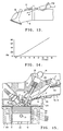
- the amount of the atomized gas that has been injected from the injector 7 which hits the surface of the heater H changes as shown in Figure 7, which represents a cross-section cut along line VII-VII in Figure 2.
- Figure 7 represents a cross-section cut along line VII-VII in Figure 2.
- the range for a direct impact on the wall surface at the lower side of the mixed gas passageway of the atomized gasoline F injected from the injection opening of the injector 7 is F1.
- the direct hitting area of the atomized gasoline changes to the area of F2 (the state in Figure 2 shown by an imaginary line). If the heater H is positioned at this location, the amount of contact increases by the effect of the gas A2, despite the fact that the amount of contact with the heater H was originally small or virtually zero.
- Figure 8 shows a typical example of a heater employed in this invention. Specifically, Figure 8 shows the heater shown in Figures 1 and 2, but heaters of the same basic construction are typically used in the systems.
- a Positive Temperature Coefficient (PTC) element 153 normally composed of a ceramic such as barium titanate or the like is affixed to a top heating plate 151 made of an aluminum alloy or the like by an electroconductive adhesive 152.
- PTC Positive Temperature Coefficient
- the bottom sheet 156 is made of a heat-resistance resin such as an epoxy or phenol resin or a ceramic material.
- a terminal plate 155 and a contact 154 are fixed together by means of a rivet 157 or the like with the contact 154 being elastically compressed to the PTC element 153.
- the top plate 151 and the bottom plate 156 form an installation part Ha to the cylinder head with one of the terminal sides being directed obliquely upward.
- the terminal elements 159A and 159B that have been fixed inside the installation part Ha are electrically connected to the terminal plate 155 and the PTC element 153 respectively by means of a cable 158 and the top plate 151.
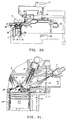
- FIG. 9 The method or control means for the supply of air A2 as the second gas is shown in Figures 9 and 10.
- the air A2 is electrically controlled through a computer.
- a control unit 70 that senses the temperature of the cooling water for the warm water jacket 24 (see Figure 1) generates a signal to the solenoid valve 71 to open unless the temperature has reached a certain level.
- the solenoid valve 71 opens the valve and connects an air transmitting pipe or tube 72 that leads from the chamber 74 and an air transmitting pipe 76 that leads to the manifold 5 to the valve.
- the chamber 74 is in a high negative pressure state as compared with the up-stream pressure state side of a throttle valve 75 when the engine is operating and cold due to the throttle valve 75 being closed. Because of this, the high pressure air flows to the air transmitting pipe.
- a check valve 73 is provided halfway on the air transmitting pipe 72, with a result that the air A2 is automatically sent in conjunction with the action of the solenoid valve 71 without causing any reverse current.
- FIG 10 shows a second embodiment for providing air A2 as the second gas with the use of a warm water valve 77.
- the warm water valve 77 is used in lieu of the aforementioned solenoid valve 71.
- the value contains a bimetal member therein and is positioned on the cylinder head so that as the cooling water for the engine is heated, the bimetal will respond to its temperature to appropriately regulate the passage 5A.
- the other piping, etc. are the same as in the case of the aforementioned solenoid with the timing of the injection being controlled by a control mechanism which is not shown in the drawings.
- the stream of fuel (shown by an imaginary line) that has been injected from the injector 7 hits the heater H thereby being heated and atomized, and it is further directed in such a way as to move toward the combustion chamber 18 together with the intake air for efficient combustion.
- the fuel stream hits the curved surface of the valve head 9a which is located in the immediate neighborhood of the valve seat 11 of the intake valve 9.
- the fuel stream is further atomized as the heat is supplied from the valve head 9a, and it expands in the shape of a fan and enters the combustion chamber 18 thereby being in the state for ideal combustion.
- the intake valve 9 is cooled as its heat is absorbed by the mixed gas so that it maintains satisfactory dimensional accuracy.
- the supply of the second gas A2 is carried out automatically by the computer control means which is responsive to cooling water temperature. It is to be understood, however, it can also be changed non-automatically with the automatic and non-automatic operations being carried out selectively.
- Figure 11 is a rough sketch showing an outline of the supply of the gasoline to the injectors.
- the injectors have been provided to correspond to each of the four cylinders of an engine.
- the injectors are connected to a fuel supply main pipe 145 by induction pipes 36.
- the gasoline inside the fuel tank 148 is supplied to fuel supply main pipe 145 via piping 47 and by fuel pump 149 and returns to the fuel tank 148.
- the gasoline has its pressure adjusted by a pressure adjuster 146 which has been arranged at the downstream of the fuel supply main pipe 145.
- Figure 12 shows typical bench test results upon start-up for the present invention.
- the number of rotations of the engine based on the amount of the injected air as the second gas when the pressure of the fuel was set constant at 3.1 kilograms per square centimeter was 1600 rpm: 0l per minute, 2000 rpms: 8l per minute and 2400 rpm: 16l per minute.
- the number of the rotations of the engine increases along with an increase in the amount of air supplied.
- Figure 13 roughly shows an experiment in which the air-transporting pipe for the injected air as the second gas was shaped spirally and externally fitted to the injector.
- the amount of air supplied per cylinder per minute at the time when the charging efficiency is approximately 80 percent will be approximately 850 rpm (in the idling state): 170l per minute, 2000 rpm: 500l per minute.
- a certain amount of air in the range between two and 16l per minute is biased and the fuel is curve-injected by means of a spiral pipe as described above, it has been learned that the rate of the direct hit of the fuel to the heater increases along with an increase in the amount of the air that is injected in a biased manner.
- a graph prepared on the basis of such data is shown in Figure 13.
- the air A2 is injected so as to cause the atomized gasoline to move toward the heater at the time when the engine is cold and the injection of air A2 is stopped and the atomized gasoline is caused to move to the combustion chamber in such a way as to avoid the heater at the time when the engine is warm.
- Figure 15 is similarly a cross-sectional view of the aforementioned engine as in the case of Figures 1 through 4.
- a heater H is buried with its surface exposed in the neighborhood of the intake manifold branched tube 5a on the bottom side of the intake port 2a of the cylinder 2.
- the injector 7 is provided in such a manner as to face the heater H and an air induction route 5D for the supply of air A2 is provided on the lower side of the injector 7.
- FIG. 16 shows an example where a cylindrically-shaped heater is provided in such an injector.
- the mixed gas injection angle from an injector assembly 57 is large and contacts to the inner peripheral surface of the cylindrically-shaped heater H2. At the time when the engine is warm, the mixed gas injection angle is reduced so that there is no contact with the heater H2.
- the injector assembly 57 has an injector accommodated within the assembly.
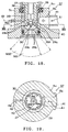
- Figure 17 is a cross-sectional view showing the construction of an injector.
- the construction of the injector 7 is common to both this embodiment and each of the aforementioned embodiments.
- the main injector body 27 is supported in an adapter 29 by means of a main body support 28.
- a needle 31 is inserted through the main body 27 with a core 32 provided at the side away from the tip of the nozzle.
- the needle 31 is biased toward the tip of the nozzle by means of a return spring 34 in such a manner as to block the nozzle 30 at the tip of the main body.
- Figure 18 is an expanded cross-sectional view of the tip of the injector assembly 57.
- Figure 19 is a cross section cut along line XIX-XIX in Figure 18.
- An injector 7 is supported through a flexible packing 38 and an O-ring 39A inside an injector support tube 5c that has been provided in the intake manifold branched tube 5a.
- An air introduction pipe 141 is installed in the injector support tube 5c and a through hole 5d which is linked therewith is provided.
- the adaptor 29 has through holes 29a at six locations and the tip of the adaptor 29 has an opening 29c in the shape of a cone formed by an inclined surface 29b.
- a first air A1 that is supplied from the first air induction pipe 141 enters an empty gap 40 between the injector support tube 5c and the adaptor 29, as shown by an arrow mark in Figure 18, and enters the adaptor 29 through each through hole 29a and gets mixed with the gasoline that is injected from the nozzle 30 in Figure 18 to form a mixed gas MG1 in an atomized state.
- An injector 7 is used as described above in the example where a heater H is used as described earlier. In this example, however, it is the state at the time when the engine is warm.
- the second air A2 (shown by an imaginary line) from the second air induction tube 142 is supplied together with the first air A1 that is supplied from the first air induction pipe 141.
- the pressure of the air supplied rises; and along with the widening of the injection angle of the mixed gas MG2, the particles of the atomized gasoline become finer and come in contact with heater H2.
- the mixed gas MG2 contacts the inner peripheral surface of the cylindrically shaped heater H2 and is evaporated at high efficiency as it is assisted by the aforementioned atomization.
- the widening of the injection angle and the further atomization of the atomized gasoline due to the aforementioned pressure elevation constitute the same phenomena as in spraying.
- the present invention provides an improved means for supplying fuel to an internal combustion engine.
- the means includes a fuel heating device and controls and means for regulating the amount of fuel to contact the heating device.
- the fuel When it is necessary to activate the fuel heating means at the time when the engine is cold, the fuel is injected in such a fashion as to satisfactorily contact the fuel heating means thereby elevating the temperature of the fuel and evaporating the fuel and guaranteeing the combustion of the fuel.
- the fuel When there is no need to use the fuel heating means when the engine is warm, the fuel is injected in such a manner as to avoid the fuel heating means, thereby greatly reducing or eliminating the amount of the fuel that comes into contact with the fuel heating means thereby improving the combustion efficiency of the fuel.
- the first gas and/or the second gas can be used as the first gas and/or the second gas.
- an inert gas which does not have any adverse effect on the exhaust gas can be used.
- the supply and the stopping of supply as well as the amount of the supply can be changed as required.
- the locations of the injector and the heater to be installed can be at any suitable location in addition to those locations described in this application.
- the shape, structure and the material of the heater can be modified and the heating element to be used can be other than a self regulating PTC element.
- the amount of the contact of the gasoline with the heater can be modified by changing the direction of the supply/injection of the second air and/or using a plurality of air induction routes.
- the above embodiments have generally been described for four-cycle reciprocating engines. However, this invention can be applied to other engines such as the rotary piston engine. This invention can also be used for the supply of fuel to the various engines and devices other than the internal combustion engine.
Landscapes
- Engineering & Computer Science (AREA)
- Chemical & Material Sciences (AREA)
- Combustion & Propulsion (AREA)
- Mechanical Engineering (AREA)
- General Engineering & Computer Science (AREA)
- Fuel-Injection Apparatus (AREA)
- Combined Controls Of Internal Combustion Engines (AREA)
Applications Claiming Priority (2)
| Application Number | Priority Date | Filing Date | Title |
|---|---|---|---|
| JP151103/93 | 1993-05-28 | ||
| JP5151103A JPH06336965A (ja) | 1993-05-28 | 1993-05-28 | 燃料供給装置 |
Publications (1)
| Publication Number | Publication Date |
|---|---|
| EP0626514A1 true EP0626514A1 (de) | 1994-11-30 |
Family
ID=15511415
Family Applications (1)
| Application Number | Title | Priority Date | Filing Date |
|---|---|---|---|
| EP94303802A Withdrawn EP0626514A1 (de) | 1993-05-28 | 1994-05-26 | Brennstoffvorwärmvorrichtung mit veränderbarer Brennstoffeinspritzung |
Country Status (2)
| Country | Link |
|---|---|
| EP (1) | EP0626514A1 (de) |
| JP (1) | JPH06336965A (de) |
Cited By (1)
| Publication number | Priority date | Publication date | Assignee | Title |
|---|---|---|---|---|
| US8091359B2 (en) | 2010-06-03 | 2012-01-10 | Ford Global Technologies, Llc | Exhaust heat recovery for engine heating and exhaust cooling |
Citations (7)
| Publication number | Priority date | Publication date | Assignee | Title |
|---|---|---|---|---|
| JPS58119966A (ja) * | 1982-01-12 | 1983-07-16 | Nissan Motor Co Ltd | 内燃機関の燃料供給装置 |
| US4676216A (en) * | 1984-10-05 | 1987-06-30 | Kabushiki Kaisha Toyota Chuo Kenkyusho | Injection nozzle |
| GB2206378A (en) * | 1987-06-19 | 1989-01-05 | Secretary Trade Ind Brit | Fuel injection arrangement |
| US5048500A (en) * | 1990-08-22 | 1991-09-17 | Texas Instruments Incorporated | Internal combustion engine with fuel injectors and heaters |
| JPH04241770A (ja) * | 1991-01-11 | 1992-08-28 | Texas Instr Japan Ltd | 内燃機関用燃料供給装置 |
| JPH04334756A (ja) * | 1991-05-02 | 1992-11-20 | Japan Electron Control Syst Co Ltd | 内燃機関の燃料供給装置 |
| DE4218896A1 (de) * | 1991-06-11 | 1992-12-24 | Nippon Denso Co | Kraftstoff-zufuhrvorrichtung fuer eine brennkraftmaschine und verfahren zu deren herstellung |
-
1993
- 1993-05-28 JP JP5151103A patent/JPH06336965A/ja not_active Withdrawn
-
1994
- 1994-05-26 EP EP94303802A patent/EP0626514A1/de not_active Withdrawn
Patent Citations (7)
| Publication number | Priority date | Publication date | Assignee | Title |
|---|---|---|---|---|
| JPS58119966A (ja) * | 1982-01-12 | 1983-07-16 | Nissan Motor Co Ltd | 内燃機関の燃料供給装置 |
| US4676216A (en) * | 1984-10-05 | 1987-06-30 | Kabushiki Kaisha Toyota Chuo Kenkyusho | Injection nozzle |
| GB2206378A (en) * | 1987-06-19 | 1989-01-05 | Secretary Trade Ind Brit | Fuel injection arrangement |
| US5048500A (en) * | 1990-08-22 | 1991-09-17 | Texas Instruments Incorporated | Internal combustion engine with fuel injectors and heaters |
| JPH04241770A (ja) * | 1991-01-11 | 1992-08-28 | Texas Instr Japan Ltd | 内燃機関用燃料供給装置 |
| JPH04334756A (ja) * | 1991-05-02 | 1992-11-20 | Japan Electron Control Syst Co Ltd | 内燃機関の燃料供給装置 |
| DE4218896A1 (de) * | 1991-06-11 | 1992-12-24 | Nippon Denso Co | Kraftstoff-zufuhrvorrichtung fuer eine brennkraftmaschine und verfahren zu deren herstellung |
Non-Patent Citations (3)
| Title |
|---|
| PATENT ABSTRACTS OF JAPAN vol. 17, no. 12 (M - 1351) 11 January 1993 (1993-01-11) * |
| PATENT ABSTRACTS OF JAPAN vol. 17, no. 181 (M - 1394) 8 April 1993 (1993-04-08) * |
| PATENT ABSTRACTS OF JAPAN vol. 7, no. 227 (M - 248)<1372> 7 October 1983 (1983-10-07) * |
Cited By (3)
| Publication number | Priority date | Publication date | Assignee | Title |
|---|---|---|---|---|
| US8091359B2 (en) | 2010-06-03 | 2012-01-10 | Ford Global Technologies, Llc | Exhaust heat recovery for engine heating and exhaust cooling |
| US8661815B2 (en) | 2010-06-03 | 2014-03-04 | Ford Global Technologies, Llc | Exhaust heat recovery for engine heating and exhaust cooling |
| US9328657B2 (en) | 2010-06-03 | 2016-05-03 | Ford Global Technologies, Llc | Exhaust heat recovery for engine heating and exhaust cooling |
Also Published As
| Publication number | Publication date |
|---|---|
| JPH06336965A (ja) | 1994-12-06 |
Similar Documents
| Publication | Publication Date | Title |
|---|---|---|
| US5056495A (en) | Fuel supply device and heating device | |
| EP0783624B1 (de) | Ladungsaufbereitungsanlage zum ermöglichen von kaltstart und warmlauf vin fremdgezündeten mit dieselstoff betriebenen kolbenbrennmaschinen | |
| US5148776A (en) | Coordinated water and fuel injection system | |
| EP0406027B1 (de) | Steuerverfahren für die Kraftstoffzufuhr und Ultraschallzerstäuber | |
| US5119794A (en) | Fuel heater for internal combustion engines | |
| US20230087858A1 (en) | Low pressure fuel and air charge forming device for a combustion engine | |
| US5056309A (en) | Internal combustion engine, particularly otto engine | |
| US4092963A (en) | Vaporizer-regulator, liquid fuel | |
| US3412718A (en) | Precision fuel metering system | |
| US5050569A (en) | Fuel injection system for an internal combustion engine and fuel heating device therefor | |
| US6067970A (en) | Fuel injection device for an internal combustion engine | |
| JPS58192963A (ja) | 内燃機関の燃料制御装置 | |
| KR20040023801A (ko) | 연료 공급 시스템 | |
| US4781165A (en) | Internal combustion engine pollutant control system | |
| EP1392964A1 (de) | Kraftstofffördersystem | |
| US7051692B1 (en) | Starting system for a marine engine | |
| US6125797A (en) | Alternate fuel system for an engine | |
| US4711222A (en) | Internal combustion engine pollutant control system | |
| JPS5853671A (ja) | 吸気管を備えた内燃機関に配置された燃料噴射弁の冷却装置 | |
| JPH04241770A (ja) | 内燃機関用燃料供給装置 | |
| RU2070653C1 (ru) | Карбюратор для двигателя внутреннего сгорания | |
| WO1987001766A1 (en) | Engine fuel supply system | |
| JPH06336965A (ja) | 燃料供給装置 | |
| US4599984A (en) | Vapor fuel supply systems for internal combustion engines | |
| JPH036844Y2 (de) |
Legal Events
| Date | Code | Title | Description |
|---|---|---|---|
| PUAI | Public reference made under article 153(3) epc to a published international application that has entered the european phase |
Free format text: ORIGINAL CODE: 0009012 |
|
| AK | Designated contracting states |
Kind code of ref document: A1 Designated state(s): DE FR GB IT NL |
|
| 17P | Request for examination filed |
Effective date: 19950421 |
|
| 17Q | First examination report despatched |
Effective date: 19950621 |
|
| STAA | Information on the status of an ep patent application or granted ep patent |
Free format text: STATUS: THE APPLICATION IS DEEMED TO BE WITHDRAWN |
|
| 18D | Application deemed to be withdrawn |
Effective date: 19951103 |