EP0626541B1 - Regelvorrichtung des Gas-Luftverhältnisses für einen Temperaturregelkreis eines Gasgerätes - Google Patents
Regelvorrichtung des Gas-Luftverhältnisses für einen Temperaturregelkreis eines Gasgerätes Download PDFInfo
- Publication number
- EP0626541B1 EP0626541B1 EP94108252A EP94108252A EP0626541B1 EP 0626541 B1 EP0626541 B1 EP 0626541B1 EP 94108252 A EP94108252 A EP 94108252A EP 94108252 A EP94108252 A EP 94108252A EP 0626541 B1 EP0626541 B1 EP 0626541B1
- Authority
- EP
- European Patent Office
- Prior art keywords
- gas
- pressure
- air
- burner
- control apparatus
- Prior art date
- Legal status (The legal status is an assumption and is not a legal conclusion. Google has not performed a legal analysis and makes no representation as to the accuracy of the status listed.)
- Expired - Lifetime
Links
Images



Classifications
-
- F—MECHANICAL ENGINEERING; LIGHTING; HEATING; WEAPONS; BLASTING
- F23—COMBUSTION APPARATUS; COMBUSTION PROCESSES
- F23N—REGULATING OR CONTROLLING COMBUSTION
- F23N1/00—Regulating fuel supply
- F23N1/02—Regulating fuel supply conjointly with air supply
- F23N1/027—Regulating fuel supply conjointly with air supply using mechanical means
-
- F—MECHANICAL ENGINEERING; LIGHTING; HEATING; WEAPONS; BLASTING
- F23—COMBUSTION APPARATUS; COMBUSTION PROCESSES
- F23N—REGULATING OR CONTROLLING COMBUSTION
- F23N2221/00—Pretreatment or prehandling
- F23N2221/08—Preheating the air
-
- F—MECHANICAL ENGINEERING; LIGHTING; HEATING; WEAPONS; BLASTING
- F23—COMBUSTION APPARATUS; COMBUSTION PROCESSES
- F23N—REGULATING OR CONTROLLING COMBUSTION
- F23N2225/00—Measuring
- F23N2225/04—Measuring pressure
-
- F—MECHANICAL ENGINEERING; LIGHTING; HEATING; WEAPONS; BLASTING
- F23—COMBUSTION APPARATUS; COMBUSTION PROCESSES
- F23N—REGULATING OR CONTROLLING COMBUSTION
- F23N2225/00—Measuring
- F23N2225/08—Measuring temperature
- F23N2225/19—Measuring temperature outlet temperature water heat-exchanger
-
- F—MECHANICAL ENGINEERING; LIGHTING; HEATING; WEAPONS; BLASTING
- F23—COMBUSTION APPARATUS; COMBUSTION PROCESSES
- F23N—REGULATING OR CONTROLLING COMBUSTION
- F23N2233/00—Ventilators
- F23N2233/06—Ventilators at the air intake
- F23N2233/08—Ventilators at the air intake with variable speed
-
- F—MECHANICAL ENGINEERING; LIGHTING; HEATING; WEAPONS; BLASTING
- F23—COMBUSTION APPARATUS; COMBUSTION PROCESSES
- F23N—REGULATING OR CONTROLLING COMBUSTION
- F23N2235/00—Valves, nozzles or pumps
- F23N2235/12—Fuel valves
- F23N2235/20—Membrane valves
-
- F—MECHANICAL ENGINEERING; LIGHTING; HEATING; WEAPONS; BLASTING
- F23—COMBUSTION APPARATUS; COMBUSTION PROCESSES
- F23N—REGULATING OR CONTROLLING COMBUSTION
- F23N2239/00—Fuels
- F23N2239/06—Liquid fuels
-
- F—MECHANICAL ENGINEERING; LIGHTING; HEATING; WEAPONS; BLASTING
- F23—COMBUSTION APPARATUS; COMBUSTION PROCESSES
- F23N—REGULATING OR CONTROLLING COMBUSTION
- F23N2241/00—Applications
- F23N2241/06—Space-heating and heating water
Definitions
- the invention relates to a gas/air ratio control apparatus for a temperature control loop for gas appliances, in particular for domestic water appliances and combined domestic water/central heating systems for the temperature control of domestic and/or heating water.
- the invention is particularly suitable for gas appliances for domestic devices up to 120 KW.
- a main boiler provided in many households for the central heating system is heated by a burner.
- a fuel/air mixture is fed to the boiler and the heat it generates is transferred to the main boiler via a heat exchanger.
- the supplied fuel can be gas.
- the firing-on and -off times for the heating boiler can be manually set with a timer so that heating water with a specified temperature can be made available for example in the morning and early evening.
- the boiler is well insulated, out as soon as the temperature of the burner boiler drops below a specified threshold value temperature, the burner is switched on via a simple on/off switching mechanism in order to increase the water temperature within the heating boiler.
- an automatic switching off of the burner is effected.
- temperature control takes place by means of an on/off control of the burner, which means that either the temperature of the water from the heating boiler is monitored and used for control of the on/off times of the burner, or the control of the on/off times is carried out via a detector mounted in a room to maintain the room temperature constant.
- flow heaters are known for domestic water supply in which the application of a large quantity of energy to a small through-flow area in a domestic water supply line results in heating of domestic water when this goes through the supply line.
- These often include electrical flow heaters which use electrical heating coils for heating. In these, control does not normally ensue by means of the temperature of the domestic water, rather the predetermination of the temperature effects the control for the heating spools to feed a quantity of electrical energy corresponding to the predetermined target temperature.
- the direct gas flow to the burner is determined by the value of the differential pressure at the Venturi valve arrangement.
- the Venturi valve arrangement controls the outlet pressure proportionally to the differential pressure.
- the gas outlet pressure is controlled as a function of the differential pressure via a Venturi arrangement which is located in an air supply line.
- a special device transforms the detected air pressure difference into a gas outlet pressure. As Fig. 5 shows, this occurs at a pressure ratio of approximately 1 to 8.
- this known system requires two pressure sensing lines 11-1, 11-2 and a transducer 11-3 for fuel/air control.
- the main function of the control system for a gas/air mixture shown in Figs. 4 and 5 is to control the efficiency of the burner via the adjustable input load so that the harmful substances in the generated combustion gases do not exceed a preset value.
- the temperature of the water drawn from the boiler must be determined, i.e. a control of the gas/air mixture must be carried out in such a manner that the temperature of the water fed to a tap etc. is maintained constant.
- a control of the gas/air mixture must be carried out in such a manner that the temperature of the water fed to a tap etc. is maintained constant.
- a thermistor sensor can be arranged in the supply to the consumer and a potentiometer can be simplified in order to regulate the predetermined water temperature.
- the downstream pressure sensing line has a leakage or is broken, the gas control valve is nevertheless opened on account of the incorrectly detected pressure difference and an increased gas supply to the burner is consequently effected.
- This excessive gas flow to the burner produces undesirable carbon monoxide on account of the insufficient air supply. This can cause a dangerous condition in the burner.
- the shown system is not cost effective.
- the system uses a transducer 11-3 for the control of the gas/air mixture which maintains the pressure ratio of 1 to 8 described above.
- the additional provision of a servo-regulator 11-4 thus increases the costs for the gas control.
- EP-A-614 046 which falls under Art. 54(3) EPC, discloses a gas/air ratio control apparatus comprising a controllable fan, a pressure-controllable valve, a pressure sensing line and two supply lines for the respective supply of the air stream and the fuel quantity to the burner.
- this known apparatus does not comprise any means detecting unusual conditions in the burner, neither does it comprise any kind of safety means so that a fail-safe operation cannot be guaranteed with this known apparatus.
- the gas/air ratio control apparatus has a number of substantial advantages in comparison to the known control apparatus.
- the gas/air ratio control device uses a controllable fan for supplying a predetermined air stream to the burner and a valve controllable via the pressure which is exclusively controlled by the absolute pressure of the air stream produced by the controllable fan.
- the absolute air pressure is taken from the controllable fan, regulation is carried out at a fuel/air mixture of 1:1.
- a fuel/air modulation range of 20% to 100% can be advantageously achieved.
- a valve is used which can be controlled via the direct pressure of the air stream generated by the fan so that no differential pressure must be detected, as was the case in the state of the art.
- Temperature control in heating domestic water in domestic appliances is therefore possible with the wide modulation range.
- the fuel/air mixture to the burner is modulated by the fuel volume and the air volume instead of by means of the fuel and air pressures.
- the oxygen level in the combustion gases is maintained constant with the inventive control apparatus and at up to 1% in a fuel/air modulation range of 20% to 100%.
- a fail-safe operation is advantageously guaranteed in the inventive gas/air ratio control apparatus, as the controllable valve is controlled via only one pressure sensing line by the absolute pressure of the air stream produced by the controllable fan.
- the controllable fan can be regulated by a measuring device which has a thermistor or a PTC-resistor provided in the piping system for supplying the domestic and/or heating water to a domestic water supply appliance.
- the measuring device generates a measurement voltage in accordance with the detected actual temperature of the domestic and/or heating water, wherein a temperature setting device includes an adjustable potentiometer and supplies a control voltage corresponding to the desired target temperature. It is advantageous to design the controllable fan such that it is controllable by a voltage, namely the voltage difference between the control voltage and the measured voltage.
- the burner has two lines for the supply of the air and the fuel, wherein it is advantageous to provide a nozzle in the fuel supply line and a restriction in the air supply line. In this way, the fuel pressure in the fuel supply line or the air pressure in the air supply line can be transformed into a specified volume flow.
- Gas is used as a fuel for the burner.
- controllable fan is arranged in the air supply line to the burner so that the burner directly receives the air stream produced by the controllable fan via the air supply line.
- the burner and the heat exchanger are preferably provided in a common housing, the housing having an exhaust gas outlet.
- controllable valve has an inlet connection, an outlet connection and a control connection which together with the fuel line that provides fuel at a constant pressure are connected with the fuel supply line to the burner and with the air supply line to the burner by a pressure sensing line.
- the considerable advantage of such a design of the controllable valve is that only one pressure sensing line must be connected with the air supply line, i.e. only a single pressure sensing line must be provided for modulating the fuel/air mixture.
- the pressure sensing line can detect any pressure in the air supply line, it is particularly advantageous to connect the pressure sensing line in such a manner with the air supply line to the burner that it transfers the absolute pressure of the air stream produced by the controllable fan to the control connection of the controllable valve.
- the controllable valve is advantageously designed such that the pressure at its outlet connection respectively follows the pressure at its control connection i.e. when the pressure at the control connection increases, the pressure at its outlet connection increases, whereas the outlet pressure is reduced in response to a pressure drop at the control connection.
- the controllable valve is preferably designed such that it sets a pressure at its outlet connection in response to a control pressure at the control connection which is the same as or less than the fuel supply pressure. It is particularly advantageous to adjust the pressure outlet connection such that it equals the control pressure fed to the control connection. This results in substantial advantages in respect of the fail-safe operation.
- the pressure of the controllable fan on the control connection of the controllable valve reduces. While the air stream remains constant, only a lower fuel pressure can be set at the fuel supply line for the burner on account of the reducing air pressure at the control connection, on account of which the fuel/air mixture supplied to the burner is reduced to a poor mixture that burns with excessive air, i.e. in a safe condition.
- the pressure produced by the controllable fan can not create pressure at the control connection of the controllable valve so that no fuel is fed to the burner. This also ensures a safe condition of the temperature control apparatus. Even if the pressure sensing line is blocked, the air pressure produced by the controllable fan can not generate any pressure at the control connection of the valve so that no fuel is supplied to the burner.
- a different dangerous condition can occur upon blocking of the exhaust gas outlet or dirt collecting in the heat exchanger.
- the pressure in the burning chamber of the burner will advantageously increase, which itself reduces the pressure drop across the fuel nozzle as well as the air restriction in the air inlet to the burner.
- a reduced fuel/air mixture is fed to the burner and the burner thus operates in a safe condition, i.e. it burns with low power.
- the gas /air ratio control apparatus further comprises a safety mechanism for closing two safety valves, the mechanism being coupled with a monitoring device arranged in the burner.
- This monitoring device can monitor the heat generation in the burner. If a missing flame is detected by the monitoring device, i.e. flame formation is too small, the fuel supply to the burner is interrupted. This can occur particularly in the case of a broken or blocked pressure sensing line if the fuel control leads a safe amount of gas over an internal breather-hole to the burner. However, if this fuel/air mixture is too low to form a flame, the monitoring device will in this case regulate the control mechanism to close the safety valve.
- the safety mechanism is also actuated by the monitoring device if the air inlet to the controllable fan is blocked.
- controllable valve is directly controlled by the controllable fan via the absolute air pressure
- controllable valve only has a single control connection and only one pressure sensing line must be provided.
- inventive control apparatus is also cheap.
- control apparatus is not influenced by variations in the ambient pressure as the control connection is part of a closed loop.
- This closed loop is formed as follows: Control connection of the controllable valve - fuel supply line to the burner - nozzle - burner - air restriction - air supply line - pressure sensing line.
- changes in the ambient pressure can not influence the setting of the control apparatus.
- a wide fuel/air modulation range of 20% to 100% is obtained.
- the advantage of this wide modulation range is that the temperature control loop with the inventive control apparatus can be used for temperature control of domestic, i.e. direct hot water.
- the control apparatus is cheap and suitable for use in controlling domestic water and heating water in water heating devices and combi boilers. This is particularly advantageous for boiler manufactures both with respect to the numerous possibilities for use and the cheap design.
- the inventive control apparatus is cheaper than a commonly known version of the regulator with a modulation spool which is used for hot water temperature control, electronic components having to be simultaneously provided in order to drive the modulation coil.
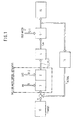
- Fig. 1 shows the temperature control loop for the temperature control of domestic and/or heating water with an inventive gas/air ratio control apparatus.
- a fixed value control is carried out in such a manner that the temperature of domestic and/or heating water flowing in a piping system 13 to a consumer 19 is maintained at a constant target temperature T Target preset by a temperature setting device 15.
- a control path in the form of a boiler 5-1 is supplied with cold water 12 via a pipeline 12-1, the water being heated by a quantity of heat Q W produced by a control device.
- the control device which produces the preset quantity of heat Q W for heating the heating and/or domestic water to the desired target temperature Target includes a measuring device 14 for determining the actual temperature T Actual of the water flowing out of the boiler 5-1, an actuator in the form of a burner 4, 5-3 which produces a quantity of heat in dependence on a supplied fuel/air mixture 1, 2; 16 , 17 and a regulator 3, 8, 9, 8-2 for supplying the air-fuel mixture to the burner.
- the gas/air ratio control apparatus consists of a controllable fan 3 which draws in air via an air inlet 9 and a controllable valve 8 which receives the fuel from a fuel supply line (not shown).
- the controllable valve is designed such that it is directly and exclusively controlled by the absolute air pressure of the air stream from the controllable fan.
- the gas/air ratio control apparatus i.e. the control apparatus, is designed such that even when a large domestic or hot water volume flow to several consumers 19 such as a bath tub, a shower, rinsing water etc. simultaneously occurs, the hot water flowing to these consumers is maintained at the preset temperature T Target .
- the fuel/air mixture is regulated within a wide modulation range of 20% to 100% in accordance with the set temperature and the temperature of the hot water delivered to the consumers.
- the temperature control apparatus designed in this manner is suitable for use in all household gas burning appliances which use pre-mix burners, the input of which should not exceed 120 kW, for example gas central heating boilers, gas water heaters, combined gas central heating boilers/water heaters and combi boilers.
- FIG. 2 shows an air inlet 9 via which a controllable fan 3 draws in inlet air 2-1 and sends an air stream 2-2 with a predetermined pressure through an air supply line 16 to the burner 4.
- a restriction 7 is provided in the air supply line.
- the burner 4 receives a predetermined quantity of fuel 1 via a fuel supply line 17 and a nozzle or injector 6 provided in the fuel supply line.
- the controllable valve 8 is connected at its inlet connection 8-2 with a fuel line, for example a gas pipe.
- the fuel line provides fuel at a constant pressure.
- the controllable valve 8 is connected at its outlet connection 8-3 with the fuel supply line 17 in order to lead a fuel quantity 1 adjusted by the control connection 8-1 to the burner 4.
- a pressure sensing line 11 is connected with the control connection 8-1 of the controllable valve 8 and also connected with the air supply line 16 in such a manner that it exclusively transfers the air pressure of the air stream produced by the controllable ventilator 3.
- the burner 4 thus burns a fuel/air mixture supplied via the nozzle 6 and the air restriction 7, the quantity of heat Q W produced in this manner being transferred to a boiler 5-1 via a heat exchanger 5-3. In this manner, cold water 12 supplied to the boiler 5-1 via a piping 12-1 is heated and heated domestic water and/or heating water is supplied to a consumer 11 via the outlet piping system 13.
- the housing in which the burner 4, the heat exchanger 5-3 and the boiler 5-1 are arranged additionally has an exhaust outlet 10 for removing the exhaust gases produced during combustion.
- the measuring device already shown in Fig. 1 is a thermistor or PTC-resistor 14 provided in the piping system 13 and detects the actual temperature T Actual of the water flowing in the piping system 13. A voltage drop across the thermistor is supplied to the fan 3 which produces an air stream 2-2 corresponding to the supplied measurement voltage.
- the temperature setting device shown in Fig. 1 but not in Fig. 2 can additionally be provided between the measuring device 14 and the controllable fan 3.
- the temperature setting device can in this case be a simple potentiometer, the controllable fan 3 then receiving a differential voltage between the measurement voltage delivered by the thermistor and the voltage delivered by the potentiometer.
- a fuel/air mixture is adjusted in the burner via the control loop in dependency on the volume flow in the piping system 13 in such a manner that the temperature of the discharged water is maintained constant.
- fuel is supplied at the outlet connection 8-3 with a pressure which corresponds to the pressure in the pressure sensing line 11.
- the fuel pressure increases with an increase in the air pressure 2-2, whereas the fuel pressure also drops at the outlet connection 8-3 with a drop in the pressure in the pressure sensing line 11.
- the valve 8 is designed such that fuel pressure is adjusted at its outlet connection 8-3 in response to the pressure at its control connection 8-1, the fuel pressure being smaller than or equal to the pressure prevailing in the fuel supply line.
- a ratio of 1:1 exists between the air pressure acting at the control connection 8-1 and the fuel pressure.
- the fuel/air mixture is adjustable in a modulation range of 20% to 100% in dependency on the temperature T Actual of the water flowing in the piping system 13.
- controllable valve 8 includes a safety mechanism 8-4 which is coupled with a monitoring device 5-2 provided in the burner housing.
- the safety mechanism 8-4 is provided to close the gas regulating safety valve 8-2 so that no fuel is supplied to the control connection 8-1.
- the monitoring device 5-2 is provided to monitor the flame formation in the burner. When the flame formation in the burner 4 is too small despite supply of a fuel/air mixture, the monitoring device generates a control signal to the safety mechanism to close both gas control safety valves 8-2 of the controllable valve 8. Thus, the monitoring device monitors the heat generation in the burner.
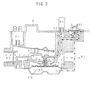
- controllable valve 8 shown schematically in Figs. 1 and 2 can be seen in Fig. 3.
- the reference signs 8-2 and 8-3 again respectively denote the inlet connection and the outlet connection of the valve.
- the control connection 8-1 is provided in the form of a servo regulator mechanism and the safety device 8-4 consists of a first automatic actuator.
- the reference sign 8-5 denotes a second automatic actuator, 8-6 a servo-valve, 8-7 a first valve, 8-8 a diaphragm valve and 8-9 a main diaphragm.
- the mode of operation of the valve i.e. the cooperation between the first valve 8-7, the diaphragm valve 8-8 and the servo-valve 8-6 can be seen in Figs. 3-1, 3-2 and 3-3.
- the servo regulator mechanism 8-1 is provided to maintain a constant burner pressure in case the gas supply pressure at the inlet connection 8-1 fluctuates. For double safety standards, a simultaneous opening and closing of the first and second valves is carried out.
- Fig. 3-1 shows the operating condition of the valve in a lead-up state.
- a constant gas pressure acts on the inlet connection 8-2, and the first and second automatic actuators 8-4, 8-5 are simultaneously actuated to open the first valve 8-7 and the servo valve 8-6.
- Gas from the servo valve flows through an opening to exert a pressure on the main diaphragm 8-9 and to effect an opening of the diaphragm valve 8-8.
- the servo regulating mechanism 8-1 responds to the outlet pressure in that it opens above pressure. This effects a release of gas from the main diaphragm 8-9 to the gas outlet 8-2 and thus reduces the opening of the diaphragm valve 8-8.
- the reciprocal effect between the servo regulating mechanism 8-1 and the diaphragm valve 8-8 produces a constant outlet pressure and an even gas flow to the burner 4 is possible (see Fig. 3-2 for the full operation state).
- the first valve 8-7, the servo valve 8-6 and the membrane valve 8-8 simultaneously close. Should either the first valve 8-7 and/or the servo valve 8-6 and/or the diaphragm valve 8-8 not close or develop a leakage, an immediate complete interruption of the gas or fuel flow is effected either by the first valve 8-7 or the diaphragm valve 8-8 or the servo valve combination 8-6 (see Fig. 3-3 for the stand-by condition).
- the fan 3 exerts a pressure on the air side of the servo regulating mechanism 8-1 via the pressure sensing line 11.
- the outlet gas 1 exerts a pressure on the gas side of the same servo regulating mechanism 8-1.
- the diaphragm of the servo regulating mechanism 8-1 is in equilibrium on account of the air pressure and the gas pressure at a ratio of 1:1.
- the main diaphragm 8-9 responds as part of the servo regulating system of the control device to an outlet pressure 1 by opening the servo regulating valve 8-10 during regulation. This effects a release of gas from the main diaphragm 8-9 via the servo regulating valve 8-10 and reduces the opening of the diaphragm valve 8-8.
- the reciprocal effect between the main diaphragm 8-9 and the diaphragm valve 8-8 provides a constant outlet pressure 1 at the gas supply line 17 or at the burner 4.
- the electronic component of the measuring device 14 controls the supply voltage to the controllable fan 3 proportionally. The fan speed varies accordingly.
- the modulated air pressure of the air stream 2-2 produced by the fan 3 regulates the outlet fuel pressure 1 via the pressure sensing line 11 and a fuel/air pressure modulation with a ratio of 1:1 is thus obtained.
- the fuel/air mixture supplied to the burner is modulated via the air restriction 7 and the nozzle 6 by means of the gas volume and the air volume instead of the gas pressure and the air pressure.
- the gas/air ratio control apparatus shown in Fig. 1 not only makes a modulating range of 20% to 100% possible, but also ensures that the control apparatus is driven in a safe condition when faults appear in the control system. Such faults relate to a blockage or leakage in the air inlet, the pressure sensing line and/or the exhaust outlet.
- the fan 3 partially compresses the air side of the regulating diaphragm 8-1. While the air flow to the burner 4 is maintained unchanged, however, the fuel supply to the burner is reduced on account of which the fuel/air mixture for the burner is adjusted to a lean mixture that burns with excessive air (safe condition).
- the fan pressure can in no way compress the air-side of the regulating diaphragm 8-1, and even if the pressure sensing line 11 is blocked, the fan pressure 2-2 can not compress the air side of the regulating diaphragm 8-1 in any way.
- no fan pressure 2-2 acts on the regulating diaphragm 8-1 so that no fuel pressure 1 and no fuel flow is effected.
- the control apparatus will supply a safe amount of fuel through an internal breather-hole to the burner.
- This fuel/air mixture is however to poor to form a flame and the flame safety system 5-2, which measures for example the ionization, actuates the safety mechanism 8-4 so that the first valve 8-7, the servo valve 8-6 and the diaphragm valve are closed simultaneously and the control valve 8 goes into the stand-by condition shown in Fig. 3-3.
- the fan pressure 2-2 drops and the fuel pressure 1 thus drops to the same extent.
- the reduced fuel/air mixture makes it possible to bring the burner into a safe combustion state.
- a monitoring device 5-2 also actuates the safety mechanism 8-4 to produce a safe condition of the control apparatus.
- the pressure increases in the burner 4 so that the pressure drop across the nozzle 6 and across the air restriction 7 is the same.
- the reduced fuel/air mixture makes it possible to operate the burner in a safe condition.
- the monitoring device 5-2 drives the control valve 8 into its stand-by state on account of poor ionization, i.e. flame formation.
- the temperature control apparatus shown in Fig. 2 is naturally independent of variations in ambient pressure as the regulating membrane 8-1 is part of a closed loop which is formed by the air-side of the diaphragm 8-1, the pressure sensing line 11, the air supply line 16, the burner 4, the fuel supply line 17 and the fuel-side of the diaphragm 8-1.
- a fuel/air modulating range between 20% and 100% is achieved with the above-described temperature control apparatus on account of which the control apparatus is suitable for use in domestic water supply.
- the control in the control valve 8 takes place at a ratio between the air pressure and the fuel pressure of 1:1. Additionally, only one pressure sensing line 11 is required to control the control valve 8.
- the control apparatus is always brought into a safe condition when faults or leakages occur in the air or fuel lines.
- the inventive control apparatus is suitable for the temperature control of hot water in heating water or combi-boilers. Furthermore, the inventive gas/air ratio control apparatus is cheaper.
Landscapes
- Engineering & Computer Science (AREA)
- Chemical & Material Sciences (AREA)
- Combustion & Propulsion (AREA)
- Mechanical Engineering (AREA)
- General Engineering & Computer Science (AREA)
- Regulation And Control Of Combustion (AREA)
Claims (13)
- Gas/Luft-Verhältnis-Steuerungsvorrichtung für eine Temperaturregelschleife für Gasgeräte, die einen Brenner umfassen, dem ein Luftstrom und eine Gasströmung zugeführt werden, insbesondere für Nutzwassersysteme und kombinierte Nutzwasser-/Zentralheizungssysteme, zur Temperaturregelung von Nutz- und/oder Heizwasser, umfassend:dadurch gekennzeichnet, daßeine drucksteuerbare Ventileinheit (8), die die Versorgung des Brenners (4, 5-3) mit einer spezifizierten Gasmenge ausschließlich in Abhängigkeit von dem Absolutdruck eines Luftstroms (2-2) steuert, und ein Gasmembranventil umfaßt, das eine Hauptmembran (8-9) und einen Ventilkörper (8-8) umfaßt, dessen Bewegung durch die Hauptmembran (8-9) steuerbar ist, um die Gasströmung zu regeln;eine Druckfühlerleitung (11) zum Übermitteln des Absolutdrucks des Luftstroms (2-2) zu einer Steuerverbindung (8-1) der Ventileinheit (8); undzwei Versorgungsleitungen (16, 17) für die Versorgung des Brenners (4) entsprechend mit dem Luftstrom (2) und der Gasmenge (1), wobei eine Düse (6) in der Kraftstoffzuführleitung und eine Drossel (?7) in der Luftzuführleitung (6) angeordnet ist;der Luftstrom (2-2) dem Brenner (4, 5-3) durch einen steuerbaren Ventilator (3) in Abhängigkeit von einer vorherbestimmten Ist-Temperatur (TActual) und einer erwünschten Soll-Temperatur (TTarget) des Heiz- und/oder Nutzwassers zugeführt wird;die Ventileinheit (8) weiterhin an ihrer Steuerverbindung (8-1) ein Servoventil (8-10) mit einer Membran umfaßt, die ausgebildet ist, um auf den durch die Druckfühlerleitung (11) übertragenen Absolutdruck ansprechend steuerbar zu sein, und mit der eine Gassteuerströmung regelbar ist, um zu bewirken, daß deren Druck auf die Hauptmembran (8-9) wirkt, um die Lage des Membranventilkörpers (8-8) einzustellen;ein erstes Sicherheitsventil (8-7) vorgesehen ist, um die Gaszufuhr zu dem Membranventil zu schließen, und ein zweites Sicherheitsventil (8-6) vorgesehen ist, um die Gaszufuhr zu dem Servoventil (8-10) zu schließen;ein Sicherheitsmechanismus (8-4, 8-5) vorgesehen ist, um die Sicherheitsventile (8-6, 8-7) im Falle einer Brennerfehlfunktion zu betätigen;der Sicherheitsmechanismus (8-4, 8-5) mit einer Überwachungseinrichtung (5-2) gekoppelt ist, die den Brennerbetrieb überwacht.
- Gas/Luft-Verhältnis-Steuerungsvorrichtung nach Anspruch 1,
dadurch gekennzeichnet, daß
der steuerbare Ventilator (3) in der Luftversorgungsleitung (9, 16) zum Brenner (4) angeordnet ist. - Gas/Luft-Verhältnis-Steuerungsvorrichtung nach Anspruch 2,
dadurch gekennzeichnet, daß
der steuerbare Ventilator (3) mittels einer Spannung steuerbar ist. - Gas/Luft-Verhältnis-Steuerungsvorrichtung nach Anspruch 1,
dadurch gekennzeichnet, daß
die Ventileinheit (8) eine Einlaßverbindung (8-2), eine Auslaßverbindung (8-3) und eine Steuerverbindung (8-1) aufweist. - Gas/Luft-Verhältnis-Steuerungsvorrichtung nach Anspruch 4,
dadurch gekennzeichnet, daßdie Einlaßverbindung (8-2) mit einer Gasleitung verbunden ist, die Gas mit konstantem Druck bereitstellt;die Auslaßverbindung (8-3) mit der Gaszuführleitung (17) zum Brenner (4) verbunden ist; unddie Steuerverbindung (8-1) über die Druckfühlerleitung (11) mit der Lufzuführleitung (16) zum Brenner verbunden ist. - Gas/Luft-Verhältnis-Steuerungsvorrichtung nach Anspruch 1,
dadurch gekennzeichnet, daß
die Druckfühlerleitung (11) mit der Luftzuführleitung (16) zum Brenner (4) derart verbunden ist, daß sie den Absolutdruck des Luftstroms (2-2) überträgt, der durch den steuerbaren Ventilator (3) zu der Steuerverbindung (8-1) der steuerbaren Ventileinheit (8) erzeugt wird. - Gas/Luft-Verhältnis-Steuerungsvorrichtung nach Anspruch 1,
dadurch gekennzeichnet, daß
die steuerbare Ventileinheit (8) den Druck an ihrer Auslaßverbindung (8-3) in Abhängigkeit von einem Druckanstieg an ihrer Steuerverbindung (8-1) erhöht. - Gas/Luft-Verhältnis-Steuerungsvorrichtung nach Anspruch 1,
dadurch gekennzeichnet, daß
die Ventileinheit (8) den Druck an ihrer Auslaßverbindung (8-3) in Abhängigkeit von einem Druckabfall an ihrer Steuerverbindung (8-1) verringert. - Gas/Luft-Verhältnis-Steuerungsvorrichtung nach Anspruch 1,
dadurch gekennzeichnet, daß
der Druck in der Gasleitung einen vorbestimmten Wert aufweist und daß ein Druck an der Auslaßverbindung (8-3) der Ventileinheit (8) in Abhängigkeit von dem Steuerdruck an ihrer Steuerverbindung (8-1) einstellbar ist, der derselbe oder kleiner als der Gasdruck ist. - Gas/Luft-Verhältnis-Steuerungsvorrichtung nach Anspruch 7 oder 8,
dadurch gekennzeichnet, daß
die Ventileinheit (8) derart konstruiert ist, daß der Druck an ihrer Auslaßverbindung (8-3) derselbe wie der auf die Steuerverbindung (8-1) ausgeübte Druck ist. - Gas/Luft-Verhältnis-Steuerungsvorrichtung nach Anspruch 1,
dadurch gekennzeichnet, daß
die in der Gaszuführleitung (17) angeordnete Düse (6) und die in der Luftzuführleitung (16) angeordnete Drossel (7) derart bemessen sind, daß der Gasdruck in der Gaszuführleitung (17) und der Luftdruck in der Luftzuführleitung (16) jeweils in einen spezifischen Volumenstrom übertragbar sind. - Gas/Luft-Verhältnis-Steuerungsvorrichtung nach Anspruch 1,
dadurch gekennzeichnet, daß
die Steuerungsvorrichtung nicht durch Veränderungen im Umgebungsdruck beeinflußbar ist, da die Steuerverbindung (8-1) Teil einer geschlossenen Schleife ist, die wie folgt gebildet ist:Steuerverbindung (8-1) der steuerbaren Ventileinheit (8);Gaszuführleitung (17) zum Brenner (4);Düse (6);Brenner (4);Luftdrossel (7);Luftzuführleitung (16); undDruckfühlerleitung (11). - Gas/Luft-Verhältnis-Steuerungsvorrichtung nach Anspruch 1,
dadurch gekennzeichnet, daß
der Ventilator (3) und die steuerbare Ventileinheit (8) derart konstruiert sind, daß die Luft-/Gasmischung (1, 2), die durch den Ventilator (3) aufgebracht wird, und die Ventileinheit (8) in einem Bereich von 20% bis 100% modullierbar sind.
Applications Claiming Priority (2)
| Application Number | Priority Date | Filing Date | Title |
|---|---|---|---|
| DE4317981 | 1993-05-28 | ||
| DE4317981A DE4317981A1 (de) | 1993-05-28 | 1993-05-28 | Gas-Luft-Verhältnisregelvorrichtung für einen Temperaturregelkreis für Gasverbrauchseinrichtungen |
Publications (2)
| Publication Number | Publication Date |
|---|---|
| EP0626541A1 EP0626541A1 (de) | 1994-11-30 |
| EP0626541B1 true EP0626541B1 (de) | 1999-01-07 |
Family
ID=6489240
Family Applications (1)
| Application Number | Title | Priority Date | Filing Date |
|---|---|---|---|
| EP94108252A Expired - Lifetime EP0626541B1 (de) | 1993-05-28 | 1994-05-27 | Regelvorrichtung des Gas-Luftverhältnisses für einen Temperaturregelkreis eines Gasgerätes |
Country Status (4)
| Country | Link |
|---|---|
| US (1) | US5630408A (de) |
| EP (1) | EP0626541B1 (de) |
| CA (1) | CA2124537A1 (de) |
| DE (2) | DE4317981A1 (de) |
Families Citing this family (58)
| Publication number | Priority date | Publication date | Assignee | Title |
|---|---|---|---|---|
| GB9503065D0 (en) * | 1995-02-16 | 1995-04-05 | British Gas Plc | Apparatus for providing an air/fuel mixture to a fully premixed burner |
| WO1996028313A1 (de) * | 1995-03-09 | 1996-09-19 | Firma J. Eberspächer | Leistungsregelung eines brenners eines heizgerätes |
| DE19538947C2 (de) * | 1995-10-19 | 1998-11-26 | Webasto Thermosysteme Gmbh | Fahrzeugheizgerät |
| US5860411A (en) * | 1997-03-03 | 1999-01-19 | Carrier Corporation | Modulating gas valve furnace control method |
| FR2765313B1 (fr) * | 1997-06-27 | 1999-09-17 | Europ Equip Menager | Bruleur a gaz a premelange total pour cuisson domestique |
| EP0926439A3 (de) * | 1997-12-23 | 2000-07-12 | Renato Montini | Gasheizkessel |
| DE19824521B4 (de) * | 1998-06-02 | 2004-12-23 | Honeywell B.V. | Regeleinrichtung für Gasbrenner |
| US6019593A (en) * | 1998-10-28 | 2000-02-01 | Glasstech, Inc. | Integrated gas burner assembly |
| DE19906935B4 (de) * | 1999-02-19 | 2006-03-23 | Robert Bosch Gmbh | Verfahren zum Betreiben eines Gasbrenners |
| ITPD20010030A1 (it) * | 2001-02-08 | 2002-08-08 | Op Controls Spa | Analizzatore d'atmosfera a fiamma perfezionato e dispositivo per il riscaldamento dell'acqua includente detto analizzatore. |
| WO2004076928A2 (en) | 2003-02-21 | 2004-09-10 | Middleby Corporation | Self-cleaning oven |
| FR2854943B1 (fr) * | 2003-05-13 | 2006-05-26 | Air Liquide | Procede de controle de bruleurs assurant le chauffage de canaux d'ecoulement de verre liquide |
| US8087407B2 (en) | 2004-03-23 | 2012-01-03 | Middleby Corporation | Conveyor oven apparatus and method |
| US9585400B2 (en) | 2004-03-23 | 2017-03-07 | The Middleby Corporation | Conveyor oven apparatus and method |
| US20070287111A1 (en) * | 2004-06-01 | 2007-12-13 | Roberts-Gordon Llc | Variable input radiant heater |
| US7748375B2 (en) * | 2005-11-09 | 2010-07-06 | Honeywell International Inc. | Negative pressure conditioning device with low pressure cut-off |
| US7644712B2 (en) * | 2005-11-09 | 2010-01-12 | Honeywell International Inc. | Negative pressure conditioning device and forced air furnace employing same |
| US7802984B2 (en) * | 2006-04-07 | 2010-09-28 | Thomas & Betts International, Inc. | System and method for combustion-air modulation of a gas-fired heating system |
| US8635997B2 (en) * | 2006-10-18 | 2014-01-28 | Honeywell International Inc. | Systems and methods for controlling gas pressure to gas-fired appliances |
| US20080124667A1 (en) * | 2006-10-18 | 2008-05-29 | Honeywell International Inc. | Gas pressure control for warm air furnaces |
| US8591221B2 (en) * | 2006-10-18 | 2013-11-26 | Honeywell International Inc. | Combustion blower control for modulating furnace |
| US8047163B2 (en) * | 2007-12-17 | 2011-11-01 | Aos Holding Company | Gas water heater with harmful gas monitoring and warning functions and the method of monitoring and warning |
| US20110040016A1 (en) | 2008-04-21 | 2011-02-17 | Yakulis Jr George | Curable compositions that form a high modulus polyurea |
| US8070481B2 (en) | 2008-05-27 | 2011-12-06 | Honeywell International Inc. | Combustion blower control for modulating furnace |
| US9316413B2 (en) | 2008-06-11 | 2016-04-19 | Honeywell International Inc. | Selectable efficiency versus comfort for modulating furnace |
| US8123518B2 (en) | 2008-07-10 | 2012-02-28 | Honeywell International Inc. | Burner firing rate determination for modulating furnace |
| US8498523B2 (en) * | 2009-02-03 | 2013-07-30 | Intellihot, Inc. | Apparatus and control method for a hybrid tankless water heater |
| US8839714B2 (en) | 2009-08-28 | 2014-09-23 | The Middleby Corporation | Apparatus and method for controlling a conveyor oven |
| DE102009048405A1 (de) * | 2009-10-06 | 2011-04-07 | Honeywell Technologies S.A.R.L. | Regeleinrichtung für Gasbrenner |
| DE102010010791A1 (de) * | 2010-03-09 | 2011-09-15 | Honeywell Technologies Sarl | Mischvorrichtung für einen Gasbrenner |
| US9695264B2 (en) | 2010-04-01 | 2017-07-04 | Ppg Industries Ohio, Inc. | High functionality polyesters and coatings comprising the same |
| US9708504B2 (en) | 2010-04-01 | 2017-07-18 | Ppg Industries Ohio, Inc. | Branched polyester polymers and coatings comprising the same |
| US10073071B2 (en) | 2010-06-07 | 2018-09-11 | David Deng | Heating system |
| US8381689B2 (en) * | 2010-11-24 | 2013-02-26 | Grand Mate Co., Ltd | Method for examining water heater safety |
| US8560127B2 (en) | 2011-01-13 | 2013-10-15 | Honeywell International Inc. | HVAC control with comfort/economy management |
| CN102072489B (zh) * | 2011-02-25 | 2012-07-04 | 凯明企业有限公司 | 燃烧器 |
| US9200802B2 (en) | 2011-04-08 | 2015-12-01 | David Deng | Dual fuel heater with selector valve |
| US9739389B2 (en) | 2011-04-08 | 2017-08-22 | David Deng | Heating system |
| US10222057B2 (en) | 2011-04-08 | 2019-03-05 | David Deng | Dual fuel heater with selector valve |
| US20130034741A1 (en) | 2011-08-04 | 2013-02-07 | Ppg Industries Ohio, Inc. | Branched polyester polymers comprising isophthalic acid and coatings comprising the same |
| CN102506198B (zh) | 2011-10-20 | 2013-05-22 | 南京普鲁卡姆电器有限公司 | 双气源燃气自适应主控阀 |
| US9175848B2 (en) * | 2011-12-05 | 2015-11-03 | David Deng | Dual fuel heater with selector valve |
| US8876524B2 (en) | 2012-03-02 | 2014-11-04 | Honeywell International Inc. | Furnace with modulating firing rate adaptation |
| US9528712B2 (en) * | 2012-11-05 | 2016-12-27 | Pat Caruso | Modulating burner system |
| US10802459B2 (en) | 2015-04-27 | 2020-10-13 | Ademco Inc. | Geo-fencing with advanced intelligent recovery |
| KR102080423B1 (ko) | 2015-12-14 | 2020-02-21 | 피피지 인더스트리즈 오하이오 인코포레이티드 | 분지형 폴리에스테르-우레탄 수지 및 이를 포함하는 코팅 |
| DE102015225581A1 (de) * | 2015-12-17 | 2017-06-22 | Convotherm Elektrogeräte GmbH | Verfahren zum Betreiben eines gewerblichen Gargeräts |
| WO2019216893A1 (en) | 2018-05-09 | 2019-11-14 | Ppg Industries Ohio, Inc. | Curable compositions and their use as coatings and footwear components |
| WO2019060513A1 (en) | 2017-09-20 | 2019-03-28 | Ppg Industries Ohio, Inc. | A COUPLING LAYER COMPOSITION COMPRISING A POLYTHIOL |
| US11286400B2 (en) | 2018-07-12 | 2022-03-29 | Ppg Industries Ohio, Inc. | Curable compositions containing reactive functional compounds and polysiloxane resins, articles of manufacture and coated articles prepared therefrom, and a method of mitigating dirt build-up on a substrate |
| US20200032997A1 (en) * | 2018-07-25 | 2020-01-30 | Haier Us Appliance Solutions, Inc. | Gas burner with a compact injet |
| US11592174B2 (en) * | 2018-07-25 | 2023-02-28 | Haier Us Appliance Solutions, Inc. | Gas burner with a pneumatic actuating injet |
| BR112021015143A2 (pt) | 2019-02-04 | 2021-09-28 | Ppg Industries Ohio, Inc. | Artigos de substituição de borracha e seu uso como componentes de calçado |
| US12359846B2 (en) | 2020-10-29 | 2025-07-15 | Johnson Controls Light Commercial Ip Gmbh | Systems and methods for operating a furnace system |
| US20240142103A1 (en) * | 2021-03-04 | 2024-05-02 | Pittway Sarl | Partially-premixed gas burner appliance |
| GB2605963B (en) * | 2021-04-16 | 2024-09-18 | Centrica Hive Ltd | Determination of a fault status of a boiler |
| JP7248744B2 (ja) * | 2021-06-28 | 2023-03-29 | 三菱重工パワーインダストリー株式会社 | ガスバーナ、及びガス焚きボイラ |
| DE102023109554A1 (de) * | 2023-04-17 | 2024-10-17 | Vaillant Gmbh | Heizgerät mit pneumatischem Gas-Luftverbund und Verfahren zu Betreiben eines Heizgerätes |
Citations (1)
| Publication number | Priority date | Publication date | Assignee | Title |
|---|---|---|---|---|
| EP0614046A1 (de) * | 1993-03-05 | 1994-09-07 | Landis & Gyr Technology Innovation AG | Steuer - und Regeleinrichtung für Gas- Feuerungsautomaten von Heizungsanlagen |
Family Cites Families (20)
| Publication number | Priority date | Publication date | Assignee | Title |
|---|---|---|---|---|
| US3299940A (en) * | 1963-06-22 | 1967-01-24 | American Smelting Refining | Burner structure |
| GB1405093A (en) * | 1971-09-18 | 1975-09-03 | Stordy Combustion Eng Ltd | Control of fuel supply to a burner |
| JPS5921455B2 (ja) * | 1976-08-18 | 1984-05-19 | 松下電器産業株式会社 | 強制給排気式燃焼制御装置 |
| US4104016A (en) * | 1977-06-03 | 1978-08-01 | Emerson Electric Co. | Cycling pilot burner control system with safety timing |
| JPS6018887B2 (ja) * | 1978-04-17 | 1985-05-13 | 松下電器産業株式会社 | 燃焼制御装置 |
| DE3010737A1 (de) * | 1980-03-20 | 1981-09-24 | Honeywell B.V., Amsterdam | Gasregelgeraet fuer brenner |
| JPS56151813A (en) * | 1980-04-28 | 1981-11-25 | Hitachi Ltd | Proportional burning method and apparatus therefor |
| JPS56166511A (en) * | 1980-05-26 | 1981-12-21 | Hitachi Ltd | Fuel supply control device |
| DE3114954A1 (de) * | 1981-04-13 | 1982-11-04 | Honeywell B.V., Amsterdam | Regeleinrichtung fuer einen gasbefeuerten wasser- oder lufterhitzer |
| JPS58224228A (ja) * | 1982-06-21 | 1983-12-26 | Matsushita Electric Ind Co Ltd | 燃焼制御装置 |
| JPS58224226A (ja) * | 1982-06-21 | 1983-12-26 | Matsushita Electric Ind Co Ltd | 燃焼制御装置 |
| EP0108349A3 (de) * | 1982-10-30 | 1985-05-02 | Joh. Vaillant GmbH u. Co. | Gasbeheizte Wärmequelle |
| JPS60165419A (ja) * | 1984-02-07 | 1985-08-28 | Matsushita Electric Ind Co Ltd | 燃焼制御装置 |
| JPS62252826A (ja) * | 1986-04-23 | 1987-11-04 | Rinnai Corp | 燃焼装置 |
| SU1573308A1 (ru) * | 1988-08-26 | 1990-06-23 | Научно-производственное объединение по автоматизации горнорудных, металлургических предприятий и энергетических объектов черной металлургии "Днепрчерметавтоматика" | Система автоматического регулировани подачи воздуха в подтопку энерготехнологического котла - утилизатора |
| SU1590855A1 (ru) * | 1988-10-24 | 1990-09-07 | Vgini I P Rabot Ogneupornoj | Cиctema abtomatичeckoгo peгулиpobahия temпepatуpы toпoчhыx гaзob |
| DE3911268A1 (de) * | 1989-04-07 | 1990-10-11 | Honeywell Bv | Regeleinrichtung fuer gasbrenner |
| SU1719796A1 (ru) * | 1989-12-06 | 1992-03-15 | Производственное Объединение "Иркутскэнерго" | Способ автоматического регулировани процесса горени |
| CH680749A5 (de) * | 1990-04-04 | 1992-10-30 | Landis & Gyr Betriebs Ag | |
| AT394909B (de) * | 1990-06-01 | 1992-07-27 | Vaillant Gmbh | Einrichtung zur kontinuierlichen ueberwachung eines variablen luftstromes |
-
1993
- 1993-05-28 DE DE4317981A patent/DE4317981A1/de not_active Withdrawn
-
1994
- 1994-05-27 EP EP94108252A patent/EP0626541B1/de not_active Expired - Lifetime
- 1994-05-27 CA CA002124537A patent/CA2124537A1/en not_active Abandoned
- 1994-05-27 DE DE69415723T patent/DE69415723T2/de not_active Expired - Fee Related
- 1994-05-27 US US08/250,277 patent/US5630408A/en not_active Expired - Lifetime
Patent Citations (1)
| Publication number | Priority date | Publication date | Assignee | Title |
|---|---|---|---|---|
| EP0614046A1 (de) * | 1993-03-05 | 1994-09-07 | Landis & Gyr Technology Innovation AG | Steuer - und Regeleinrichtung für Gas- Feuerungsautomaten von Heizungsanlagen |
Also Published As
| Publication number | Publication date |
|---|---|
| EP0626541A1 (de) | 1994-11-30 |
| DE69415723D1 (de) | 1999-02-18 |
| US5630408A (en) | 1997-05-20 |
| DE69415723T2 (de) | 1999-06-10 |
| DE4317981A1 (de) | 1994-12-01 |
| CA2124537A1 (en) | 1994-11-29 |
Similar Documents
| Publication | Publication Date | Title |
|---|---|---|
| EP0626541B1 (de) | Regelvorrichtung des Gas-Luftverhältnisses für einen Temperaturregelkreis eines Gasgerätes | |
| US4706881A (en) | Self-correcting microprocessor control system and method for a furnace | |
| US5322216A (en) | System and method for controlling outlet water temperature of an instantaneous water heater | |
| JP4956391B2 (ja) | 流体の漏洩検知方法 | |
| US4792089A (en) | Self-correcting microprocessor control system and method for a furnace | |
| CA1228795A (en) | Fuel gas control | |
| US5092519A (en) | Control system for water heaters | |
| JP2900015B2 (ja) | 給湯装置 | |
| KR100192924B1 (ko) | 연소장치 | |
| EP4352414B1 (de) | Verfahren zur steuerung des betriebs eines gaskessels | |
| KR910002734B1 (ko) | 연소제어장치 | |
| JP2990665B2 (ja) | 給湯装置 | |
| JP3446502B2 (ja) | 燃焼制御装置 | |
| JPH04309713A (ja) | マルチガス燃焼装置 | |
| JP3215557B2 (ja) | 燃焼装置 | |
| EP0131235A1 (de) | Heizeinrichtung | |
| JPH08210700A (ja) | 給湯器 | |
| JPS5832059Y2 (ja) | ガス比例制御弁 | |
| WO1989004442A1 (en) | Instantaneous hot water system | |
| JP2537782B2 (ja) | 燃焼装置 | |
| EP0989366A1 (de) | Ventileinheit zur automatischen Regelung der Brenngasdurchflussmenge | |
| JPS5835904Y2 (ja) | 流体流量制御装置 | |
| JPH04335914A (ja) | 燃焼装置 | |
| JPS6048440A (ja) | 給湯器の湯温制御装置 | |
| JPH079296B2 (ja) | 燃焼器の異状検出方法 |
Legal Events
| Date | Code | Title | Description |
|---|---|---|---|
| PUAI | Public reference made under article 153(3) epc to a published international application that has entered the european phase |
Free format text: ORIGINAL CODE: 0009012 |
|
| AK | Designated contracting states |
Kind code of ref document: A1 Designated state(s): DE FR GB IT NL |
|
| 17P | Request for examination filed |
Effective date: 19950523 |
|
| 17Q | First examination report despatched |
Effective date: 19960403 |
|
| GRAG | Despatch of communication of intention to grant |
Free format text: ORIGINAL CODE: EPIDOS AGRA |
|
| GRAG | Despatch of communication of intention to grant |
Free format text: ORIGINAL CODE: EPIDOS AGRA |
|
| GRAH | Despatch of communication of intention to grant a patent |
Free format text: ORIGINAL CODE: EPIDOS IGRA |
|
| GRAH | Despatch of communication of intention to grant a patent |
Free format text: ORIGINAL CODE: EPIDOS IGRA |
|
| GRAA | (expected) grant |
Free format text: ORIGINAL CODE: 0009210 |
|
| AK | Designated contracting states |
Kind code of ref document: B1 Designated state(s): DE FR GB IT NL |
|
| REF | Corresponds to: |
Ref document number: 69415723 Country of ref document: DE Date of ref document: 19990218 |
|
| ET | Fr: translation filed | ||
| PGFP | Annual fee paid to national office [announced via postgrant information from national office to epo] |
Ref country code: DE Payment date: 19990610 Year of fee payment: 6 |
|
| PLBE | No opposition filed within time limit |
Free format text: ORIGINAL CODE: 0009261 |
|
| STAA | Information on the status of an ep patent application or granted ep patent |
Free format text: STATUS: NO OPPOSITION FILED WITHIN TIME LIMIT |
|
| 26N | No opposition filed | ||
| PGFP | Annual fee paid to national office [announced via postgrant information from national office to epo] |
Ref country code: FR Payment date: 20001120 Year of fee payment: 7 |
|
| PGFP | Annual fee paid to national office [announced via postgrant information from national office to epo] |
Ref country code: GB Payment date: 20001122 Year of fee payment: 7 |
|
| PGFP | Annual fee paid to national office [announced via postgrant information from national office to epo] |
Ref country code: NL Payment date: 20001130 Year of fee payment: 7 |
|
| PG25 | Lapsed in a contracting state [announced via postgrant information from national office to epo] |
Ref country code: DE Free format text: LAPSE BECAUSE OF NON-PAYMENT OF DUE FEES Effective date: 20010301 |
|
| PG25 | Lapsed in a contracting state [announced via postgrant information from national office to epo] |
Ref country code: GB Free format text: LAPSE BECAUSE OF NON-PAYMENT OF DUE FEES Effective date: 20010527 |
|
| PG25 | Lapsed in a contracting state [announced via postgrant information from national office to epo] |
Ref country code: NL Free format text: LAPSE BECAUSE OF NON-PAYMENT OF DUE FEES Effective date: 20011201 |
|
| GBPC | Gb: european patent ceased through non-payment of renewal fee |
Effective date: 20010527 |
|
| PG25 | Lapsed in a contracting state [announced via postgrant information from national office to epo] |
Ref country code: FR Free format text: LAPSE BECAUSE OF NON-PAYMENT OF DUE FEES Effective date: 20020131 |
|
| NLV4 | Nl: lapsed or anulled due to non-payment of the annual fee |
Effective date: 20011201 |
|
| PG25 | Lapsed in a contracting state [announced via postgrant information from national office to epo] |
Ref country code: IT Free format text: LAPSE BECAUSE OF NON-PAYMENT OF DUE FEES Effective date: 20050527 |