EP0626733B1 - Verfahren zum Verbinden eines metallischen Ableiters an eine Faser- oder Schaumgerüst als Trägerteil enthaltende Elektrode für einen elektrochemischen Generator und bei diesem Verfahren enthaltene Elektrode - Google Patents
Verfahren zum Verbinden eines metallischen Ableiters an eine Faser- oder Schaumgerüst als Trägerteil enthaltende Elektrode für einen elektrochemischen Generator und bei diesem Verfahren enthaltene Elektrode Download PDFInfo
- Publication number
- EP0626733B1 EP0626733B1 EP94401155A EP94401155A EP0626733B1 EP 0626733 B1 EP0626733 B1 EP 0626733B1 EP 94401155 A EP94401155 A EP 94401155A EP 94401155 A EP94401155 A EP 94401155A EP 0626733 B1 EP0626733 B1 EP 0626733B1
- Authority
- EP
- European Patent Office
- Prior art keywords
- core
- electrode
- retaining
- main core
- fact
- Prior art date
- Legal status (The legal status is an assumption and is not a legal conclusion. Google has not performed a legal analysis and makes no representation as to the accuracy of the status listed.)
- Expired - Lifetime
Links
- 238000000034 method Methods 0.000 title claims abstract description 30
- 238000005304 joining Methods 0.000 title description 2
- 239000006260 foam Substances 0.000 claims abstract description 19
- 238000003466 welding Methods 0.000 claims abstract description 19
- PXHVJJICTQNCMI-UHFFFAOYSA-N Nickel Chemical compound [Ni] PXHVJJICTQNCMI-UHFFFAOYSA-N 0.000 claims description 28
- 239000002184 metal Substances 0.000 claims description 20
- 229910052751 metal Inorganic materials 0.000 claims description 20
- 229910052759 nickel Inorganic materials 0.000 claims description 14
- 230000006835 compression Effects 0.000 claims description 13
- 238000007906 compression Methods 0.000 claims description 13
- 229910000831 Steel Inorganic materials 0.000 claims description 6
- 239000010959 steel Substances 0.000 claims description 6
- BFDHFSHZJLFAMC-UHFFFAOYSA-L nickel(ii) hydroxide Chemical compound [OH-].[OH-].[Ni+2] BFDHFSHZJLFAMC-UHFFFAOYSA-L 0.000 claims description 5
- XLOMVQKBTHCTTD-UHFFFAOYSA-N Zinc monoxide Chemical compound [Zn]=O XLOMVQKBTHCTTD-UHFFFAOYSA-N 0.000 claims description 4
- 239000000463 material Substances 0.000 claims description 4
- NDVLTYZPCACLMA-UHFFFAOYSA-N silver oxide Chemical compound [O-2].[Ag+].[Ag+] NDVLTYZPCACLMA-UHFFFAOYSA-N 0.000 claims description 4
- OKTJSMMVPCPJKN-UHFFFAOYSA-N Carbon Chemical compound [C] OKTJSMMVPCPJKN-UHFFFAOYSA-N 0.000 claims description 2
- 239000000956 alloy Substances 0.000 claims description 2
- 229910045601 alloy Inorganic materials 0.000 claims description 2
- CXKCTMHTOKXKQT-UHFFFAOYSA-N cadmium oxide Inorganic materials [Cd]=O CXKCTMHTOKXKQT-UHFFFAOYSA-N 0.000 claims description 2
- CFEAAQFZALKQPA-UHFFFAOYSA-N cadmium(2+);oxygen(2-) Chemical compound [O-2].[Cd+2] CFEAAQFZALKQPA-UHFFFAOYSA-N 0.000 claims description 2
- 229910052799 carbon Inorganic materials 0.000 claims description 2
- 229920002635 polyurethane Polymers 0.000 claims description 2
- 239000004814 polyurethane Substances 0.000 claims description 2
- 229910001923 silver oxide Inorganic materials 0.000 claims description 2
- UGZADUVQMDAIAO-UHFFFAOYSA-L zinc hydroxide Chemical compound [OH-].[OH-].[Zn+2] UGZADUVQMDAIAO-UHFFFAOYSA-L 0.000 claims description 2
- 229910021511 zinc hydroxide Inorganic materials 0.000 claims description 2
- 229940007718 zinc hydroxide Drugs 0.000 claims description 2
- 239000011787 zinc oxide Substances 0.000 claims description 2
- 239000013543 active substance Substances 0.000 claims 4
- 239000000835 fiber Substances 0.000 claims 2
- 239000011262 electrochemically active material Substances 0.000 description 4
- 238000004873 anchoring Methods 0.000 description 3
- 230000008569 process Effects 0.000 description 3
- 238000012423 maintenance Methods 0.000 description 2
- 229910000679 solder Inorganic materials 0.000 description 2
- 238000005476 soldering Methods 0.000 description 2
- 239000004480 active ingredient Substances 0.000 description 1
- 239000000654 additive Substances 0.000 description 1
- 238000005452 bending Methods 0.000 description 1
- 239000004020 conductor Substances 0.000 description 1
- 230000006872 improvement Effects 0.000 description 1
- 238000004519 manufacturing process Methods 0.000 description 1
- 230000004048 modification Effects 0.000 description 1
- 238000012986 modification Methods 0.000 description 1
- 230000009467 reduction Effects 0.000 description 1
- 238000009864 tensile test Methods 0.000 description 1
- 230000008719 thickening Effects 0.000 description 1
Images


Classifications
-
- B—PERFORMING OPERATIONS; TRANSPORTING
- B23—MACHINE TOOLS; METAL-WORKING NOT OTHERWISE PROVIDED FOR
- B23K—SOLDERING OR UNSOLDERING; WELDING; CLADDING OR PLATING BY SOLDERING OR WELDING; CUTTING BY APPLYING HEAT LOCALLY, e.g. FLAME CUTTING; WORKING BY LASER BEAM
- B23K11/00—Resistance welding; Severing by resistance heating
- B23K11/10—Spot welding; Stitch welding
- B23K11/11—Spot welding
-
- B—PERFORMING OPERATIONS; TRANSPORTING
- B23—MACHINE TOOLS; METAL-WORKING NOT OTHERWISE PROVIDED FOR
- B23K—SOLDERING OR UNSOLDERING; WELDING; CLADDING OR PLATING BY SOLDERING OR WELDING; CUTTING BY APPLYING HEAT LOCALLY, e.g. FLAME CUTTING; WORKING BY LASER BEAM
- B23K20/00—Non-electric welding by applying impact or other pressure, with or without the application of heat, e.g. cladding or plating
- B23K20/16—Non-electric welding by applying impact or other pressure, with or without the application of heat, e.g. cladding or plating with interposition of special material to facilitate connection of the parts, e.g. material for absorbing or producing gas
-
- H—ELECTRICITY
- H01—ELECTRIC ELEMENTS
- H01M—PROCESSES OR MEANS, e.g. BATTERIES, FOR THE DIRECT CONVERSION OF CHEMICAL ENERGY INTO ELECTRICAL ENERGY
- H01M4/00—Electrodes
- H01M4/02—Electrodes composed of, or comprising, active material
- H01M4/64—Carriers or collectors
- H01M4/70—Carriers or collectors characterised by shape or form
- H01M4/80—Porous plates, e.g. sintered carriers
-
- H—ELECTRICITY
- H01—ELECTRIC ELEMENTS
- H01M—PROCESSES OR MEANS, e.g. BATTERIES, FOR THE DIRECT CONVERSION OF CHEMICAL ENERGY INTO ELECTRICAL ENERGY
- H01M50/00—Constructional details or processes of manufacture of the non-active parts of electrochemical cells other than fuel cells, e.g. hybrid cells
- H01M50/50—Current conducting connections for cells or batteries
- H01M50/531—Electrode connections inside a battery casing
- H01M50/533—Electrode connections inside a battery casing characterised by the shape of the leads or tabs
-
- H—ELECTRICITY
- H01—ELECTRIC ELEMENTS
- H01M—PROCESSES OR MEANS, e.g. BATTERIES, FOR THE DIRECT CONVERSION OF CHEMICAL ENERGY INTO ELECTRICAL ENERGY
- H01M50/00—Constructional details or processes of manufacture of the non-active parts of electrochemical cells other than fuel cells, e.g. hybrid cells
- H01M50/50—Current conducting connections for cells or batteries
- H01M50/531—Electrode connections inside a battery casing
- H01M50/534—Electrode connections inside a battery casing characterised by the material of the leads or tabs
-
- H—ELECTRICITY
- H01—ELECTRIC ELEMENTS
- H01M—PROCESSES OR MEANS, e.g. BATTERIES, FOR THE DIRECT CONVERSION OF CHEMICAL ENERGY INTO ELECTRICAL ENERGY
- H01M50/00—Constructional details or processes of manufacture of the non-active parts of electrochemical cells other than fuel cells, e.g. hybrid cells
- H01M50/50—Current conducting connections for cells or batteries
- H01M50/531—Electrode connections inside a battery casing
- H01M50/536—Electrode connections inside a battery casing characterised by the method of fixing the leads to the electrodes, e.g. by welding
-
- H—ELECTRICITY
- H01—ELECTRIC ELEMENTS
- H01M—PROCESSES OR MEANS, e.g. BATTERIES, FOR THE DIRECT CONVERSION OF CHEMICAL ENERGY INTO ELECTRICAL ENERGY
- H01M4/00—Electrodes
- H01M4/02—Electrodes composed of, or comprising, active material
- H01M4/64—Carriers or collectors
- H01M4/70—Carriers or collectors characterised by shape or form
- H01M4/80—Porous plates, e.g. sintered carriers
- H01M4/808—Foamed, spongy materials
-
- Y—GENERAL TAGGING OF NEW TECHNOLOGICAL DEVELOPMENTS; GENERAL TAGGING OF CROSS-SECTIONAL TECHNOLOGIES SPANNING OVER SEVERAL SECTIONS OF THE IPC; TECHNICAL SUBJECTS COVERED BY FORMER USPC CROSS-REFERENCE ART COLLECTIONS [XRACs] AND DIGESTS
- Y02—TECHNOLOGIES OR APPLICATIONS FOR MITIGATION OR ADAPTATION AGAINST CLIMATE CHANGE
- Y02E—REDUCTION OF GREENHOUSE GAS [GHG] EMISSIONS, RELATED TO ENERGY GENERATION, TRANSMISSION OR DISTRIBUTION
- Y02E60/00—Enabling technologies; Technologies with a potential or indirect contribution to GHG emissions mitigation
- Y02E60/10—Energy storage using batteries
-
- Y—GENERAL TAGGING OF NEW TECHNOLOGICAL DEVELOPMENTS; GENERAL TAGGING OF CROSS-SECTIONAL TECHNOLOGIES SPANNING OVER SEVERAL SECTIONS OF THE IPC; TECHNICAL SUBJECTS COVERED BY FORMER USPC CROSS-REFERENCE ART COLLECTIONS [XRACs] AND DIGESTS
- Y02—TECHNOLOGIES OR APPLICATIONS FOR MITIGATION OR ADAPTATION AGAINST CLIMATE CHANGE
- Y02P—CLIMATE CHANGE MITIGATION TECHNOLOGIES IN THE PRODUCTION OR PROCESSING OF GOODS
- Y02P70/00—Climate change mitigation technologies in the production process for final industrial or consumer products
- Y02P70/50—Manufacturing or production processes characterised by the final manufactured product
-
- Y—GENERAL TAGGING OF NEW TECHNOLOGICAL DEVELOPMENTS; GENERAL TAGGING OF CROSS-SECTIONAL TECHNOLOGIES SPANNING OVER SEVERAL SECTIONS OF THE IPC; TECHNICAL SUBJECTS COVERED BY FORMER USPC CROSS-REFERENCE ART COLLECTIONS [XRACs] AND DIGESTS
- Y10—TECHNICAL SUBJECTS COVERED BY FORMER USPC
- Y10T—TECHNICAL SUBJECTS COVERED BY FORMER US CLASSIFICATION
- Y10T29/00—Metal working
- Y10T29/49—Method of mechanical manufacture
- Y10T29/49002—Electrical device making
- Y10T29/49108—Electric battery cell making
- Y10T29/49114—Electric battery cell making including adhesively bonding
Definitions
- the present invention relates to a linking method of a metallic connection on an electrode, whose core has a fibrous or foam-like structure, for generator electrochemical, and in particular for batteries accumulators intended for industrial applications and tensile.
- connection is generally made by welding. We apply the edge of the core to the connection and weld it under pressure. Patent application FR-A-2 604 302 and the US-A-5,085,956 describes such methods. In the case of a porous core, making such a weld is facilitated by a modification of the surface state of the connection. Patent FR-2 111 024 teaches the deposit of sintered nickel on the face of the connection attached to the core.
- the object of the present invention is to provide a improved process which significantly improves these performances.
- the subject of the present invention is a method of bonding of a metal connection to an electrode, of which the core has a fibrous or foam-like structure, for electrochemical generator, process by which on an edge of said core at least one metal strip, and we weld with compression said strip and said core called main, process characterized by the fact that, prior to welding, we have at least the right to the weld zone an additional part called the core maintenance of a nature similar to that of said soul main.
- said metal strip is interposed between said main soul and said soul of maintenance.
- two are implemented metal strips on both sides of the set formed by said main core and said retaining core.
- the height of metal strap united to said souls is less than half the height of said retaining core.
- connection connection is made prior to the introduction of the material electrochemically active in said main core and said retaining core, operation followed by compression overall setting to a predetermined thickness of said electrode.
- an electrode according to the invention we start by linking them with compression of said main core and said retaining core, then we introduce into this set of material electrochemically active electrically conductive, we performs overall compression for thickening of said electrode, and said soldering the connection.
- the electrochemically active material is not conductive, the latter is not introduced into the main core and the retaining core at the soldering zone of said connection.
- one or other of the said cores is provided with several perforations, for example, of diameter between 2 and 8 mm, with a pitch between 5 and 50 mm. After compression, the two souls overlap.
- This anchoring can also be improved by joining the main core and the retaining core beforehand by spot, electrical or ultrasonic welding.
- the electrochemically active materials can be chosen, for example, from nickel hydroxide, hydrurable alloys, carbon, cadmium oxide, zinc oxide, zinc hydroxide, silver oxide, etc. Conventional additives are added to these different active ingredients.
- the material of said main core and of said retaining core can be chosen from a nickel foam, a nickel-plated steel foam, a nickel-plated or silvered polyurethane felt.
- said strip is made of nickel-plated steel with a thickness of between 0.05 and 1 mm; said main core and said retaining core are made of nickel foam with a basis weight between 200 g / m 2 and 2000 g / m 2 , the initial thickness being between 0.5 mm and 5 mm for the main core, and between 0.5 mm and 5 mm for the retaining core; preferably the grammage is of the order of 500 g / m 2 and the initial thickness of the main core and of the retaining core is 1.7 mm.
- the retaining core When the mechanical stresses of the connection are intended to be particularly high, it is preferable to choose for the retaining core a grammage greater than that of the main core.
- said main core is made of nickel foam with a basis weight between 500 g / m 2 and 900 g / m 2 , and an initial thickness between 1.4 mm and 2.5 mm
- said retaining core is in nickel foam with a basis weight between 500 g / m 2 and 1500 g / m 2 and an initial thickness between 1.4 mm and 2.5 mm.
- the present invention also relates to an electrode for electrochemical generator comprising a core main fibrous or foam-like and a strip metallic welded together, characterized in that said electrode further comprises an additional part called retaining core, of the same kind as said core main and arranged at least to the right of the area of welding, so that the total thickness of said core main and said retaining core is that predetermined of said electrode.
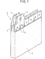
- FIG. 1 shows an electrode 1 which is not part of the present invention. It has a core 2 of nickel foam with an initial thickness of 1.7 mm and a grammage of 500 g / m 2 . Nickel hydroxide has been introduced into this core except in zone 3 where the connection with the connection will take place. The pasted core 2 is compressed to a thickness of 1 mm. Then applied on either side of the zone 3 of the core 2, and along the entire width of the electrode, metal strips 4 and 5 made of nickel-plated steel, 0.1 mm thick. These strips and zone 3 are compressed and spot welded (the welding spots are referenced 6).
- the electrode 1 has a width of 70 mm and a height of 150 mm.
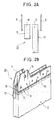
- FIGS. 2A and 2B there is a main core 12 similar to the core 2 and two metal strips 14 and 15 similar to the strips 4 and 5; but there is between the strip 15 and the main core 12, in line with the weld zone provided for connection, along the entire width of the electrode, a retaining core 17 of nickel foam of initial thickness 1, 7 mm and grammage 500 g / m 2 .
- the height of the part 18 of the retaining core 17 which will be involved in the welding is of the order of one third of the total height of this retaining core (which is for example 20 mm for an electrode of height 150 mm ).
- the connection is made by spot welding (references 16).
- Electrochemically active material (nickel hydroxide) is introduced into the cores 12 and 17 except in the weld zones 13 and 18 and the assembly is compressed to a final thickness of electrode 20 equal to 1 mm.
- FIGS. 3A and 3B show an alternative embodiment of an electrode according to the invention.
- the main core 22 of nickel foam with an initial thickness of 1.7 mm and a grammage of 500 g / m 2 is associated with a retaining core 27 similar to the core 17 and to a strip 24 similar to the strips 14 and 15 mentioned above, but 0.2 mm thick.
- the connection is made by an electric weld with the thumbwheel shown schematically by the line 25.
- the cores 22 and 27 are pasted with nickel hydroxide, except in the zones 23 and 28 involved in the welding. The assembly then undergoes compression until an electrode 30 of thickness equal to 1 mm is obtained.
- Table I records the results of the various tests. Breaking force daN Number of turns Mohm impedance Example I 4.1 2 8.3 Example II 13 28 4.4 Example III 11 > 50 3.6 This table very clearly shows the progress brought by the implementation of the method according to the invention.
- the central strip of Example III is internal to the electrode, and does not risk damaging the separators situated on either side of this electrode in the accumulator; short circuits can thus be avoided.
- the electrochemically active material is conductive, it is possible to paste the zones 23 and 28 of the cores 22 and 27 before the connection is made. Optimal capacity of the electrode can therefore be obtained.
- the retaining core and the main core were made of identical nickel foams. But, depending on the optimal characteristic sought, it is possible to vary the thickness and grammage of selected foams, within the limits indicated above.
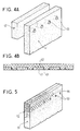
- FIGS. 4A and 4B show an improvement to the method according to the invention according to which, before any operation, the retaining core 42 is anchored in the main core 41.
- the retaining core 42 is anchored in the main core 41.
- the nickel foam of the main core 41 with an initial thickness of 1.7 mm and a grammage of 500 g / m 2, holes 43 of diameter 6 mm are provided, with a pitch of 15 mm.
- the diameter of the holes can vary between 2 and 8 mm and the pitch between 5 and 50 mm.
- the retaining core 42 initially has the same characteristics as the main core 41. After compression, the two cores overlap, as shown in FIG. 4B in diagrammatic section.
- FIG. 5 shows another means of anchoring the cores 51 and 52 respectively similar to the cores 41 and 42.
- An initial compression and a spot welding are carried out; the diameter of the welding points 53 is 2 mm and can vary between 1 and 4 mm; the pitch of these points is 15 mm and can vary between 5 and 50 mm.
- the line of these solder points is located below the solder area of the connection. To better illustrate this arrangement, reference is made to line 55 which corresponds to the edge of the strip 14 in FIG. 2B.
- Figure 6 shows an alternative embodiment of a electrode 60 obtained by implementing the method according to the invention.
- the electrode 60 comprises a central strip 64 similar to the strip 24 of the electrode of Figure 3B.
- Souls 61 and 62 are analogous to souls 51 and 52 of FIG. 5, and the central strip 64.
- a compression a spot welding 63 of the two cores together, a welding by points 67 of the two souls with the strip.
- the electrode is then pasted over its entire height, then compressed.
- connection and the retaining core can be applied over only part of the width of the electrode. Preferably this part will be at least equal at half the width of the electrode.
Landscapes
- Chemical & Material Sciences (AREA)
- Chemical Kinetics & Catalysis (AREA)
- Electrochemistry (AREA)
- General Chemical & Material Sciences (AREA)
- Engineering & Computer Science (AREA)
- Mechanical Engineering (AREA)
- Battery Electrode And Active Subsutance (AREA)
- Cell Electrode Carriers And Collectors (AREA)
- Connection Of Batteries Or Terminals (AREA)
- Electrodes For Compound Or Non-Metal Manufacture (AREA)
Claims (15)
- Verfahren zur Verbindung eines metallischen Ableiters mit einer Elektrode, deren Kern eine Faser oder Schaumstruktur aufweist, für einen elektrochemischen Generator, nach dem an einem Rand des Kerns wenigstens ein Metallband angebracht wird und das Band und der Hauptkern genannte Kern unter Zusammendrücken verschweißt werden, dadurch gekennzeichnet, daß vor dem Schweißen wenigstens gerade in der Schweißzone ein zusätzliches Teil, Haltekern genannt, mit einer Beschaffenheit angeordnet wird, die zu der des Hauptkerns analog ist.
- Verfahren zur Verbindung eines metallischen Ableiters mit einer Elektrode nach Anspruch 1, dadurch gekennzeichnet, daß das Metallband zwischen den Hauptkern und den Haltekern eingefügt wird.
- Verfahren zur Verbindung eines metallischen Ableiters mit einer Elektrode nach Anspruch 1, dadurch gekennzeichnet, daß zwei Metallbänder beiderseits der von dem Hauptkern und dem Haltekern gebildeten Anordnung ausgeführt werden.
- Verfahren zur Verbindung eines metallischen Ableiters mit einer Elektrode nach einem der Ansprüche 1 bis 3, dadurch gekennzeichnet, daß die Verbindung vor der Einführung des elektrochemisch aktiven Materials in den Hauptkern und den Haltekern ausgeführt wird, dem Vorgang ein gesamtes Zusammendrücken folgt, um der Elektrode eine vorbestimmte Dicke zu geben.
- Verfahren zur Verbindung eines metallischen Ableiters mit einer Elektrode nach einem der Ansprüche 1 bis 3, dadurch gekennzeichnet, daß mit dem Verbinden durch Zusammendrücken des Hauptkerns und des Haltekerns miteinander begonnen wird, dann in diese Anordnung elektrisch leitendes, elektrochemisch aktives Material eingeführt wird, ein gesamtes Zusammendrücken durchgeführt wird, um der Elektrode eine vorbestimmte Dicke zu geben, und die Verschweißung des Ableiters ausgeführt wird.
- Verfahren zur Verbindung eines metallischen Ableiters mit einer Elektrode nach einem der Ansprüche 1 bis 3, dadurch gekennzeichnet, daß mit dem Verbinden durch Zusammendrücken des Hauptkerns und des Haltekerns miteinander begonnen wird, dann in diese Anordnung, außer in Höhe der Schweißzone für den Ableiter nichtleitendes, elektrochemisch aktives Material eingeführt wird, ein gesamtes Zusammendrücken durchgeführt wird, um der Elektrode eine vorbestimmte Dicke zu geben, und die Verschweißung des Ableiters ausgeführt wird.
- Verfahren zur Ausführung nach einem der Ansprüche 4 bis 6, dadurch gekennzeichnet, daß, um die Verankerung zwischen dem Hauptkern und dem Haltekern zu steigern, in dem einen oder dem anderen der Kerne mehrere Löcher mit einem Durchmesser zwischen 2 und 8 mm mit einem Abstand zwischen 5 und 50 mm vorgesehen werden.
- Verfahren zur Ausführung nach einem der Ansprüche 4 bis 6, dadurch gekennzeichnet, daß die Verankerung zwischen dem Hauptkern und dem Haltekern durch eine Elektro- oder Ultraschall-Punktschweißung gesteigert wird.
- Verfahren nach einem der Ansprüche 1 bis 8, dadurch gekennzeichnet, daß die elektrochemisch aktiven Materialien aus Nickelhydroxid, den hydrierbaren Legierungen, Kohlenstoff, Cadmiumoxid, Zinkoxid, Zinkhydroxid, Silberoxid ausgewählt werden.
- Verfahren nach einem der Ansprüche 1 bis 8, dadurch gekennzeichnet, daß das Material des Hauptkerns und des Haltekerns aus Nickelschaum, Schaum aus vernickeltem Stahl, Filz aus vernickeltem oder versilbertem Polyurethan ausgewählt werden.
- Verfahren nach einem der vorhergehenden Ansprüche, dadurch gekennzeichnet, daß das Band aus vernickeltem Stahl mit einer Dicke zwischen 0,05 und 1 mm besteht, daß der Hauptkern und der Haltekern aus einem Nickelschaum mit einem Flächengewicht zwischen 200 g/m2 und 2000 g/m2 bestehen, wobei die Anfangsdicke zwischen 0,5 mm und 5 mm für den Hauptkern und zwischen 0,5 mm und 5 mm für den Haltekern beträgt.
- Verfahren nach Anspruch 11, dadurch gekennzeichnet, daß das Flächengewicht in der Größenordnung von 500 g/m2 liegt und daß die Anfangsdicke des Hauptkerns und des Haltekerns 1,7 mm beträgt.
- Verfahren nach einem der Ansprüche 1 bis 10, dadurch gekennzeichnet, daß das Band aus vernickeltem Stahl mit einer Dicke zwischen 0,05 mm und 1 mm besteht, daß der Hauptkern aus einem Nickelschaum mit einem Flächengewicht zwischen 500 g/m2 und 900 g/m2 und einer Anfangsdicke zwischen 1,4 mm und 2,5 mm besteht, und daß der Haltekern aus einem Nickelschaum mit einem Flächengewicht zwischen 500 g/m2 und 1500 g/m2 und einer Anfangsdicke zwischen 1,4 und 2,5 mm besteht.
- Verfahren nach einem der vorhergehenden Ansprüche, dadurch gekennzeichnet, daß die Höhe des Metallbandes, die mit den Kernen fest verbunden ist, geringer als die halbe Höhe des Haltekerns ist.
- Elektrode für einen elektrochemischen Generator, die einen Hauptkern, der faserig oder vom Schaumtyp ist, und ein Metallband umfaßt, die zusammen verschweißt sind, dadurch gekennzeichnet, daß die Elektrode außerdem ein zusätzliches Teil, Haltekern genannt, aufweist, das die gleiche Beschaffenheit wie der Hauptkern hat und wenigstens gerade in der Schweißzone angeordnet ist, so daß die Gesamtdicke des Hauptkerns und des Haltekerns diejenige ist, die für die Elektrode vorbestimmt ist.
Applications Claiming Priority (2)
| Application Number | Priority Date | Filing Date | Title |
|---|---|---|---|
| FR9306314 | 1993-05-26 | ||
| FR9306314A FR2705834B1 (fr) | 1993-05-26 | 1993-05-26 | Procédé de liaison d'une connexion métallique sur une électrode dont l'âme a une structure fibreuse ou de type mousse pour générateur électrochimique, et électrode obtenue. |
Publications (2)
| Publication Number | Publication Date |
|---|---|
| EP0626733A1 EP0626733A1 (de) | 1994-11-30 |
| EP0626733B1 true EP0626733B1 (de) | 1998-10-28 |
Family
ID=9447478
Family Applications (1)
| Application Number | Title | Priority Date | Filing Date |
|---|---|---|---|
| EP94401155A Expired - Lifetime EP0626733B1 (de) | 1993-05-26 | 1994-05-25 | Verfahren zum Verbinden eines metallischen Ableiters an eine Faser- oder Schaumgerüst als Trägerteil enthaltende Elektrode für einen elektrochemischen Generator und bei diesem Verfahren enthaltene Elektrode |
Country Status (6)
| Country | Link |
|---|---|
| US (2) | US5558681A (de) |
| EP (1) | EP0626733B1 (de) |
| JP (1) | JPH0773865A (de) |
| AT (1) | ATE172815T1 (de) |
| DE (1) | DE69414172T2 (de) |
| FR (1) | FR2705834B1 (de) |
Families Citing this family (23)
| Publication number | Priority date | Publication date | Assignee | Title |
|---|---|---|---|---|
| DE19542162C2 (de) * | 1995-11-11 | 2000-11-23 | Abb Research Ltd | Überstrombegrenzer |
| JPH10188996A (ja) * | 1996-12-26 | 1998-07-21 | Matsushita Electric Ind Co Ltd | 鉛蓄電池用格子体 |
| US5851698A (en) * | 1997-01-31 | 1998-12-22 | Ovonic Battery Company, Inc. | Nickel-metal hydride batteries having high power electrodes and low-resistance electrode connections |
| US6330925B1 (en) | 1997-01-31 | 2001-12-18 | Ovonic Battery Company, Inc. | Hybrid electric vehicle incorporating an integrated propulsion system |
| ZA986942B (en) | 1997-08-08 | 1999-02-08 | Duracell Inc | Reinforced coiled electrode assemblies and methods of producing same |
| CN100336245C (zh) | 1998-01-14 | 2007-09-05 | 杨泰和 | 储放电装置的低内阻汇流结构 |
| US6238819B1 (en) * | 1998-01-23 | 2001-05-29 | Stork, N.V. | Metal foam support, electrode and method of making same |
| JP3831525B2 (ja) * | 1998-06-30 | 2006-10-11 | 三洋電機株式会社 | 電池 |
| RU2148284C1 (ru) * | 1998-07-23 | 2000-04-27 | Открытое акционерное общество "Сатурн" | Способ изготовления оксидно-никелевого электрода щелочного аккумулятора |
| FR2787925B1 (fr) * | 1998-12-24 | 2001-03-09 | Cit Alcatel | Generateur electrochimique dans lequel une electrode a un bord renforce par un feuillard |
| FR2789229B1 (fr) * | 1999-02-01 | 2001-03-30 | Cit Alcatel | Electrode spiralee a support tridimensionnel |
| JP4566303B2 (ja) | 1999-07-22 | 2010-10-20 | 本田技研工業株式会社 | ニッケル水素電池用正極板 |
| JP2001052711A (ja) * | 1999-08-05 | 2001-02-23 | Honda Motor Co Ltd | 蓄電池用電極板 |
| CN1240148C (zh) * | 2000-11-01 | 2006-02-01 | 索尼株式会社 | 电池及其制造方法 |
| US7179562B2 (en) * | 2003-02-14 | 2007-02-20 | Quallion Llc | Battery electrode assembly and fabrication method therefor |
| JP4462245B2 (ja) * | 2006-07-19 | 2010-05-12 | トヨタ自動車株式会社 | 2次電池、積層2次電池および組電池 |
| US20100273043A1 (en) * | 2007-04-24 | 2010-10-28 | Temic Automotive Electric Motors Gmbh | Electrochemical cell with weld points connections and energy storage assembly |
| KR101679095B1 (ko) * | 2009-02-05 | 2016-12-06 | 이브이티 파워, 아이엔씨. | 전기 집전 장치용 mcm |
| RU2482569C1 (ru) * | 2011-09-23 | 2013-05-20 | Открытое акционерное общество "Завод автономных источников тока" | Способ изготовления волоконного оксидно-никелевого электрода щелочного никель-кадмиевого аккумулятора |
| GB201203997D0 (en) * | 2012-03-07 | 2012-04-18 | Bae Systems Plc | Electrical energy storage structures |
| KR102624807B1 (ko) * | 2019-05-14 | 2024-01-16 | 주식회사 엘지에너지솔루션 | 전극 조립체 및 이의 검사 방법 |
| CN114520336B (zh) * | 2022-04-21 | 2022-08-02 | 宁德时代新能源科技股份有限公司 | 集流体及其制造方法和设备、及集流体预制件 |
| FR3155542A1 (fr) * | 2023-11-21 | 2025-05-23 | John Cockerill Hydrogen Belgium | Unité électrodique réalisée par soudage résistif, cellule électrolytique et électrolyseur en comportant, et procédé de fabrication |
Family Cites Families (14)
| Publication number | Priority date | Publication date | Assignee | Title |
|---|---|---|---|---|
| US2861115A (en) * | 1956-02-20 | 1958-11-18 | Nickel Cadmium Battery Corp | Battery plate and tab assembly |
| DE1063233B (de) * | 1957-11-27 | 1959-08-13 | Willi Krebs | Elektrode fuer alkalische Sammler, deren Traeger der aktiven Masse aus miteinander versinterten Metallfaeden od. dgl. besteht, sowie Verfahren und Vorrichtung zu deren Herstellung |
| GB1370777A (en) * | 1970-10-06 | 1974-10-16 | Ever Ready Co | Electrodes for electro-chemical cells |
| DE2524774C3 (de) * | 1975-06-04 | 1979-01-04 | Volkswagenwerk Ag, 3180 Wolfsburg | Negative Kobalt-Elektrode für alkalische Akkumulatoren und Verfahren zu ihrer Herstellung |
| JPS5734668A (en) * | 1980-08-11 | 1982-02-25 | Matsushita Electric Ind Co Ltd | Manufacture of cell electrode |
| JPS59105264A (ja) * | 1982-12-07 | 1984-06-18 | Yuasa Battery Co Ltd | アルカリ蓄電池極板の製造法 |
| JPS60235360A (ja) * | 1984-05-08 | 1985-11-22 | Yuasa Battery Co Ltd | アルカリ電池用導電芯体の製造法 |
| JPH0695457B2 (ja) * | 1985-05-13 | 1994-11-24 | 松下電器産業株式会社 | 電池用極板の製造法 |
| GB8630857D0 (en) * | 1986-12-24 | 1987-02-04 | Sylva Ind Ltd | Electrical contact tab |
| FR2652450B1 (fr) * | 1989-09-22 | 1991-11-29 | Accumulateurs Fixes | Procede de fabrication d'une electrode a support de type mousse pour generateur electrochimique et electrode obtenue par ce procede. |
| DE3935368C1 (de) * | 1989-10-24 | 1991-05-29 | Deutsche Automobilgesellschaft Mbh, 3000 Hannover, De | |
| FR2670608B1 (fr) * | 1990-12-13 | 1996-07-19 | Accumulateurs Fixes | Procede de liaison d'une connexion metallique sur une electrode a support de type mousse pour generateur electrochimique et electrode obtenue par ce procede. |
| DE4104865C1 (de) * | 1991-02-16 | 1992-04-09 | Deutsche Automobilgesellschaft Mbh, 3300 Braunschweig, De | |
| US5456813A (en) * | 1993-01-26 | 1995-10-10 | Societe Anonyme: Saft | Method of joining a metal connection tab to an electro-chemical cell electrode having a foam-type support, and an electrode obtained by the method |
-
1993
- 1993-05-26 FR FR9306314A patent/FR2705834B1/fr not_active Expired - Fee Related
-
1994
- 1994-05-24 US US08/248,238 patent/US5558681A/en not_active Expired - Fee Related
- 1994-05-25 AT AT94401155T patent/ATE172815T1/de not_active IP Right Cessation
- 1994-05-25 DE DE69414172T patent/DE69414172T2/de not_active Expired - Fee Related
- 1994-05-25 EP EP94401155A patent/EP0626733B1/de not_active Expired - Lifetime
- 1994-05-26 JP JP6113099A patent/JPH0773865A/ja active Pending
-
1996
- 1996-02-22 US US08/604,925 patent/US5667915A/en not_active Expired - Fee Related
Also Published As
| Publication number | Publication date |
|---|---|
| ATE172815T1 (de) | 1998-11-15 |
| FR2705834A1 (fr) | 1994-12-02 |
| US5558681A (en) | 1996-09-24 |
| US5667915A (en) | 1997-09-16 |
| DE69414172T2 (de) | 1999-05-12 |
| DE69414172D1 (de) | 1998-12-03 |
| FR2705834B1 (fr) | 1995-06-30 |
| JPH0773865A (ja) | 1995-03-17 |
| EP0626733A1 (de) | 1994-11-30 |
Similar Documents
| Publication | Publication Date | Title |
|---|---|---|
| EP0626733A1 (de) | Verfahren zum Verbinden eines metallischen Ableiters an eine Faser- oder Schaumgerüst als Trägerteil enthaltende Elektrode für einen elektrochemischen Generator und bei diesem Verfahren enthaltene Elektrode | |
| EP1014463B1 (de) | Elektrochemischer Generator mit einer durch ein Band randverstärkten Elektrode | |
| EP0658946B1 (de) | Elektrodeplatte mit schaumförmigem Träger für elektrochemische Generatoren und Verfahren zur ihrer Herstellung | |
| JP5089656B2 (ja) | 非水電解質二次電池用電極構造体、その製造方法、および非水電解質二次電池 | |
| EP2842185B1 (de) | Buchse zur formung eines anschlusses für eine lithiumspeicherbatterie und zugehörige speicherbatterie | |
| EP0418774B1 (de) | Verfahren zur Herstellung einer Elektrode mit schaumförmigem Träger für elektrochemischen Generator und bei diesem Verfahren erhaltene Elektrode | |
| EP0658945B1 (de) | Elektrodeplatte mit schaumförmigem Träger für elektrochemische Generatoren und Verfahren zur Herstellung einer solchen Elektrode | |
| CH637697A5 (fr) | Electrode pour dispositif electro-chimique. | |
| WO2015181508A1 (fr) | Accumulateur au plomb-acide et procédé de fabrication d'un tel accumulateur | |
| US6132898A (en) | Battery with a conductive plate | |
| EP0490316B1 (de) | Verfahren zum Verbinden eines metallischen Ableiters an eine ein Schaumgerüst als Trägerteil enthaltende Elektrode für einen elektrochemischen Generator und bei diesem Verfahren erhaltene Elektrode | |
| WO2017216021A1 (fr) | Electrode pour faisceau electrochimique d'un accumulateur metal-ion ou d'un supercondensateur, procede de realisation du faisceau et de l'accumulateur associes | |
| FR2824667A1 (fr) | Connectique interne pour generateur electrochimique de forte puissance | |
| EP0516535B1 (de) | Verfahren zum Verbinden eines metallischen Ableiters an eine ein Schaumgerüst als Trägerteil enthaltende Elektrode für einen elektrochemischen Generator und bei diesem Verfahren erhaltene Elektrode | |
| FR2800917A1 (fr) | Electrode a support tridimentionnel utilisable dans un generateur secondaire a electrolyte alcalin | |
| EP1026760A1 (de) | Spiralförmig gewickelter dreidimensionaler Elektroden-Support | |
| EP0427141B1 (de) | Verfahren zum Beziehen einer Elektrode mit schaumförmigem Träger für elektroschemischen Generator und nach diesem Verfahren erhaltene Elektrode | |
| FR2806211A1 (fr) | Ruban faisant office d'ossature pour electrodes a structure fibreuse, plaque d'electrode fabriquee a partir de celui-ci, et leur procede de fabrication | |
| FR3021812A1 (fr) | Accumulateur au plomb-acide, procede de fabrication d'un tel accumulateur et procede de fabrication d'une electrode | |
| JPH0963575A (ja) | 電池用極板の製造方法 | |
| EP0601263A1 (de) | Batterie und Elektroden für eine solche |
Legal Events
| Date | Code | Title | Description |
|---|---|---|---|
| PUAI | Public reference made under article 153(3) epc to a published international application that has entered the european phase |
Free format text: ORIGINAL CODE: 0009012 |
|
| AK | Designated contracting states |
Kind code of ref document: A1 Designated state(s): AT BE CH DE DK ES FR GB GR IE IT LI LU MC NL PT SE |
|
| 17P | Request for examination filed |
Effective date: 19950303 |
|
| 17Q | First examination report despatched |
Effective date: 19960206 |
|
| GRAG | Despatch of communication of intention to grant |
Free format text: ORIGINAL CODE: EPIDOS AGRA |
|
| GRAG | Despatch of communication of intention to grant |
Free format text: ORIGINAL CODE: EPIDOS AGRA |
|
| GRAH | Despatch of communication of intention to grant a patent |
Free format text: ORIGINAL CODE: EPIDOS IGRA |
|
| GRAH | Despatch of communication of intention to grant a patent |
Free format text: ORIGINAL CODE: EPIDOS IGRA |
|
| GRAA | (expected) grant |
Free format text: ORIGINAL CODE: 0009210 |
|
| RAP1 | Party data changed (applicant data changed or rights of an application transferred) |
Owner name: ALCATEL ALSTHOM COMPAGNIE GENERALE D'ELECTRICITE |
|
| AK | Designated contracting states |
Kind code of ref document: B1 Designated state(s): AT BE CH DE DK ES FR GB GR IE IT LI LU MC NL PT SE |
|
| PG25 | Lapsed in a contracting state [announced via postgrant information from national office to epo] |
Ref country code: NL Free format text: LAPSE BECAUSE OF FAILURE TO SUBMIT A TRANSLATION OF THE DESCRIPTION OR TO PAY THE FEE WITHIN THE PRESCRIBED TIME-LIMIT Effective date: 19981028 Ref country code: IT Free format text: LAPSE BECAUSE OF FAILURE TO SUBMIT A TRANSLATION OF THE DESCRIPTION OR TO PAY THE FEE WITHIN THE PRE;WARNING: LAPSES OF ITALIAN PATENTS WITH EFFECTIVE DATE BEFORE 2007 MAY HAVE OCCURRED AT ANY TIME BEFORE 2007. THE CORRECT EFFECTIVE DATE MAY BE DIFFERENT FROM THE ONE RECORDED.SCRIBED TIME-LIMIT Effective date: 19981028 Ref country code: GR Free format text: LAPSE BECAUSE OF NON-PAYMENT OF DUE FEES Effective date: 19981028 Ref country code: ES Free format text: THE PATENT HAS BEEN ANNULLED BY A DECISION OF A NATIONAL AUTHORITY Effective date: 19981028 Ref country code: AT Free format text: LAPSE BECAUSE OF FAILURE TO SUBMIT A TRANSLATION OF THE DESCRIPTION OR TO PAY THE FEE WITHIN THE PRESCRIBED TIME-LIMIT Effective date: 19981028 |
|
| REF | Corresponds to: |
Ref document number: 172815 Country of ref document: AT Date of ref document: 19981115 Kind code of ref document: T |
|
| REG | Reference to a national code |
Ref country code: CH Ref legal event code: EP |
|
| REF | Corresponds to: |
Ref document number: 69414172 Country of ref document: DE Date of ref document: 19981203 |
|
| REG | Reference to a national code |
Ref country code: IE Ref legal event code: FG4D Free format text: FRENCH |
|
| PG25 | Lapsed in a contracting state [announced via postgrant information from national office to epo] |
Ref country code: SE Free format text: LAPSE BECAUSE OF FAILURE TO SUBMIT A TRANSLATION OF THE DESCRIPTION OR TO PAY THE FEE WITHIN THE PRESCRIBED TIME-LIMIT Effective date: 19990128 Ref country code: PT Free format text: LAPSE BECAUSE OF FAILURE TO SUBMIT A TRANSLATION OF THE DESCRIPTION OR TO PAY THE FEE WITHIN THE PRESCRIBED TIME-LIMIT Effective date: 19990128 Ref country code: DK Free format text: LAPSE BECAUSE OF FAILURE TO SUBMIT A TRANSLATION OF THE DESCRIPTION OR TO PAY THE FEE WITHIN THE PRESCRIBED TIME-LIMIT Effective date: 19990128 |
|
| GBT | Gb: translation of ep patent filed (gb section 77(6)(a)/1977) |
Effective date: 19990114 |
|
| RAP4 | Party data changed (patent owner data changed or rights of a patent transferred) |
Owner name: ALCATEL |
|
| RAP4 | Party data changed (patent owner data changed or rights of a patent transferred) |
Owner name: ALCATEL |
|
| NLV1 | Nl: lapsed or annulled due to failure to fulfill the requirements of art. 29p and 29m of the patents act | ||
| PGFP | Annual fee paid to national office [announced via postgrant information from national office to epo] |
Ref country code: GB Payment date: 19990413 Year of fee payment: 6 |
|
| PGFP | Annual fee paid to national office [announced via postgrant information from national office to epo] |
Ref country code: FR Payment date: 19990419 Year of fee payment: 6 |
|
| PGFP | Annual fee paid to national office [announced via postgrant information from national office to epo] |
Ref country code: DE Payment date: 19990420 Year of fee payment: 6 |
|
| PG25 | Lapsed in a contracting state [announced via postgrant information from national office to epo] |
Ref country code: LU Free format text: LAPSE BECAUSE OF NON-PAYMENT OF DUE FEES Effective date: 19990525 |
|
| PG25 | Lapsed in a contracting state [announced via postgrant information from national office to epo] |
Ref country code: LI Free format text: LAPSE BECAUSE OF NON-PAYMENT OF DUE FEES Effective date: 19990531 Ref country code: CH Free format text: LAPSE BECAUSE OF NON-PAYMENT OF DUE FEES Effective date: 19990531 Ref country code: BE Free format text: LAPSE BECAUSE OF NON-PAYMENT OF DUE FEES Effective date: 19990531 |
|
| PG25 | Lapsed in a contracting state [announced via postgrant information from national office to epo] |
Ref country code: IE Free format text: LAPSE BECAUSE OF NON-PAYMENT OF DUE FEES Effective date: 19990820 |
|
| PLBE | No opposition filed within time limit |
Free format text: ORIGINAL CODE: 0009261 |
|
| STAA | Information on the status of an ep patent application or granted ep patent |
Free format text: STATUS: NO OPPOSITION FILED WITHIN TIME LIMIT |
|
| REG | Reference to a national code |
Ref country code: IE Ref legal event code: FD4D |
|
| 26N | No opposition filed | ||
| REG | Reference to a national code |
Ref country code: FR Ref legal event code: CD |
|
| BERE | Be: lapsed |
Owner name: ALCATEL ALSTHOM CIE GENERALE D'ELECTRICITE Effective date: 19990531 |
|
| PG25 | Lapsed in a contracting state [announced via postgrant information from national office to epo] |
Ref country code: MC Free format text: LAPSE BECAUSE OF NON-PAYMENT OF DUE FEES Effective date: 19991130 |
|
| REG | Reference to a national code |
Ref country code: CH Ref legal event code: PL |
|
| PG25 | Lapsed in a contracting state [announced via postgrant information from national office to epo] |
Ref country code: GB Free format text: LAPSE BECAUSE OF NON-PAYMENT OF DUE FEES Effective date: 20000525 |
|
| GBPC | Gb: european patent ceased through non-payment of renewal fee |
Effective date: 20000525 |
|
| PG25 | Lapsed in a contracting state [announced via postgrant information from national office to epo] |
Ref country code: FR Free format text: LAPSE BECAUSE OF NON-PAYMENT OF DUE FEES Effective date: 20010131 |
|
| PG25 | Lapsed in a contracting state [announced via postgrant information from national office to epo] |
Ref country code: DE Free format text: LAPSE BECAUSE OF NON-PAYMENT OF DUE FEES Effective date: 20010301 |
|
| REG | Reference to a national code |
Ref country code: FR Ref legal event code: ST |