EP0627199B1 - Chirurgische Nadel-Nähfaden-Befestigung zur kontrollierten Trennung des Nähfadens - Google Patents
Chirurgische Nadel-Nähfaden-Befestigung zur kontrollierten Trennung des Nähfadens Download PDFInfo
- Publication number
- EP0627199B1 EP0627199B1 EP94108370A EP94108370A EP0627199B1 EP 0627199 B1 EP0627199 B1 EP 0627199B1 EP 94108370 A EP94108370 A EP 94108370A EP 94108370 A EP94108370 A EP 94108370A EP 0627199 B1 EP0627199 B1 EP 0627199B1
- Authority
- EP
- European Patent Office
- Prior art keywords
- needle
- suture
- dies
- die
- crimping
- Prior art date
- Legal status (The legal status is an assumption and is not a legal conclusion. Google has not performed a legal analysis and makes no representation as to the accuracy of the status listed.)
- Expired - Lifetime
Links
Images



Classifications
-
- A—HUMAN NECESSITIES
- A61—MEDICAL OR VETERINARY SCIENCE; HYGIENE
- A61B—DIAGNOSIS; SURGERY; IDENTIFICATION
- A61B17/00—Surgical instruments, devices or methods
- A61B17/04—Surgical instruments, devices or methods for suturing wounds; Holders or packages for needles or suture materials
- A61B17/06—Needles ; Sutures; Needle-suture combinations; Holders or packages for needles or suture materials
- A61B17/06004—Means for attaching suture to needle
-
- B—PERFORMING OPERATIONS; TRANSPORTING
- B21—MECHANICAL METAL-WORKING WITHOUT ESSENTIALLY REMOVING MATERIAL; PUNCHING METAL
- B21G—MAKING NEEDLES, PINS OR NAILS OF METAL
- B21G1/00—Making needles used for performing operations
- B21G1/08—Making needles used for performing operations of hollow needles or needles with hollow end, e.g. hypodermic needles, larding-needles
Definitions
- the present invention relates to the attachment of surgical sutures to surgical needles.
- the invention relates to apparatus for the attachment of surgical needles to surgical sutures to provide a combined surgical needle-suture device possessing controlled suture release characteristics.
- apparatus is disclosed in Applicant's EP-A-426377, on which the pre-characterising part of claims 1 and 7 below is based.
- needle-suture combinations in which a suture or ligature is attached to the shank end of a needle.
- Such needle-suture combinations are provided for a wide variety of monofilament and braided suture materials, both absorbable and no-absorbable, e.g., catgut, silk, nylon, polyester, polypropylene, linen, cotton, and absorbable synthetic materials such as polymers and copolymers of glycolic and lactic acids.
- Needle-suture combinations fall into two general classes: standard needle attachment and removable or detachable needle attachment.
- standard needle attachment the suture is securely attached to the needle and is not intended to be separable therefrom, except by cutting or severing the suture.
- Removable needle attachment by contrast, is such that the needle is separable from the suture in response to a force exerted by the surgeon.
- Minimum acceptable forces required to separate a needle from a suture for various suture sizes are set forth in the United States Pharmacopeia (USP XXII 1990).
- USP XXII 1990 The United States Pharmacopeia prescribes minimum individual pull-out forces and minimum average pull-out forces as measured for five needle-suture combinations.
- the minimum pull-out forces for both standard and removable needle-suture attachment set forth in the United States Pharmacopeia are hereby incorporated by reference.
- One typical method for securing a suture to a needle involves providing a cylindrical recess in the shank end of a needle and securing a suture therein.
- U.S. Patent No. 1,558,037 teaches the addition of a cement material to such a substantially cylindrical recess to secure the suture therein. Additional methods for bonding a suture within a needle bore are described in U.S. Patent Nos. 2,928,395 (adhesives) and 3,394,704 (bonding agents).
- a suture may be secured within an axial bore in a needle by swaging the needle in the region of the recess, see, e.g., U.S. Patent No. 1,250,114.
- Additional prior art methods for securing a suture within a needle bore include expansion of a catgut suture through the application of heat (U.S. Patent No. 1,665,216), inclusion of protruding teeth within the axial bore to grasp an inserted suture (U.S. Patent No. 1,678,361) and knotting the end of the suture to be inserted within the bore to secure the suture therein (U.S. Patent No. 1,757,129).
- U.S. Patent Nos. 3,890,975 and 3,980,177 teach swaging a suture within a needle bore such that the suture has a pull-out value of 3 to 26 ounces.
- Alternative detachable attachment methods include providing a weakened suture segment (U.S. Patent No. 3,949,756), lubricant tipping the end of a suture to be inserted in the axial bore of a needle (U.S. Patent No. 3,963,031) and pretensioning a suture that is swaged within an axial needle bore (U.S. Patent No. 3,875,946). See also, U.S. Patent Nos. 3,799,169; 3,880,167; 3,924,630; 3,926,194; 3,943,933; 3,981,307; 4,124,027; and 4,127,133.
- Another method for attaching a suture to a needle involves the use of tubing which is secured to the shank end of the needle and to the suture.
- tubing preferably silver
- the tube may be attached to the needle by pressure or soldering and to the ligature by pressure or cementing.
- shank of the needle be of reduced cross section and that the furthest extremity of the reduced diameter shank section be provided with a spike or point upon which the suture may be secured prior to the tube application.
- U.S. Patent No. 2,240,330 describes a tubing attachment method whereby the tubing and suture are releasably secured to the needle.
- the needle and tubing are provided with cooperating catch and abutment means which are released one from the other by rotating the needle 90° relative to the tubing (or vice versa).
- the tubing is manufactured from spring-tempered carbon steel or chrome nickel steel and is secured to the suture by heating the tubing and then swaging to the suture.
- U.S. Patent No. 3,311,100 relates to a flexible composite suture having a tandem linkage.
- the needle is secured to a flexible suture leader manufactured from a readily sterilizable plastic such as nylon, linear polyethylene, isotactic polypropylene, polyester, silk or other proteinaceous material, e.g., by inserting and crimping the leader within an axial bore in the needle shank.
- the opposite end of the suture leader is crimped within a connector sleeve of a thin walled metal tubing, e.g., stainless steel.
- the opposite end of the tubing is crimped around a stiff suture, e.g., monofilament stainless steel.
- U.S. Patent No. 5,139,514 describes a combined surgical needle-suture device in which a surgical needle having a shank of reduced cross-section is attached to a suture through a shrinkable tubing, or micro-ferrule, which is fitted about the needle shank and a portion of the suture.
- Application of energy to the shrinkable tubing brings the tubing into engagement with both the needle shank and the suture.
- the physical and chemical characteristics of the shrinkable tubing material, the relative diameters of the tubing, the needle shank and the suture, and the amount of energy applied to the tubing may be controlled to provide a needle-suture combination having a desired pull-out force. It is thus possible to produce standard needle-suture combinations and removable needle-suture combinations using a single attachment process and a common inventory of materials.
- U.S. Patent No. 3,875,946, employing the procedure described therein, combined surgical needle-suture devices can be obtained with the following average pull-out forces: Average Pull-Out Suture Size Force/Ounces/g 8/0 1-2/28 - 57 7/0 1-3/28 - 85 6/0 2-5/57 - 142 5/0 3-7/28 - 200 4/0 3-15/28 - 426 3/0 3-23/28 - 653 2/0 3-26/28 - 738 1/0 10-26/284 - 738 1 10-26/284 - 738 2 and larger 10-26/284 - 738
- pull-out forces are obtained by prestressing the suture, i.e., by applying tension to the suture after the tip of the suture has been inserted into an axial bore, or recess, formed in the blunt end of the needle and the needled suture has been swaged so that the force required to pull the suture out of the recess exceeds the minimum limits on needle attachment set forth in the United States Pharmacopeia but is less than the actual tensile strength of the suture used.
- the force required to move the end of the suture relative to the needle recess drops to the desired pull-out value, where the tension is released.
- a prevailing controlled release needle-suture attachment is a swage or crimp attachment, such as described in the foregoing U.S. Patents 3,890,975 and 3,980,177.
- Swaging dies for achieving removable needle attachment are disclosed in U.S. Patents 4,060,885 and 4,072,041.
- Conventional crimp operations of the type disclosed in these patents are difficult to control.
- a crimp is created between several dies which close to a fixed gap. Any variation in the crimping dies, the apparatus for closing the dies, the needle size, the hole size, or the suture size will increase variability of the needle suture attachment.
- one conventional crimping method requires that the back end of the needle be struck with two opposed dies.
- the needle is then rotated 90° and the dies are arranged to strike the needle a second time.
- the first strike changes a round hole into one of elliptical shape, i.e., major and minor axes.
- the act of rotating the needle 90° and repeating the operation to some extent completes the attachment.
- these procedures increase handling during manufacture and the likelihood that unacceptable attachment will be achieved.
- rotating the suture and needle before the attachment is complete is likely to dislodge the suture tip in whole or part prior to completion of the attachment, resulting in unacceptable attachment.
- multiple opposing die hits may produce a distorted needle end which results in corresponding asymmetry of tissue apertures and trauma during use.
- U.S. Patent Nos. 5,046,350 to Proto et al. and 5,099,676 to Proto et al. disclose crimping or swaging die configurations for attaching surgical needles and sutures.
- the split ring die disclosed in the U.S. Patent 5,046,350 includes a relief zone defined between a pair of extensions. A needle positioned between a pair of the split ring dies is stricken by the extensions whereby the superfluous material caused by the swaging action collects within the relief zone.
- the novel configuration of the split ring die provides a more uniform swage while the needle retains its circular symmetry in the area of suture attachment.
- U.S. Patent No. 5,099,676 discloses a die featuring a novel clover leaf shape which is defined by a generally circular surface having a series of interconnected alternating individual convex and concave curved surfaces.
- the convex and concave surfaces permit needle material swaged during the crimping process to flow from the convex portions which perform the actual crimping action to the concave areas so as to collect within the concave portions.
- the clover leaf dies provide unique attachment of the suture components and also maintains the symmetry of the product.
- the present invention is defined in the appended claims and is directed to a unique die arrangement and the swage formed thereby which overcome the inherent disadvantages associated with conventional crimping dies and processes, particularly applied to a suture needle to achieve removable needle-suture attachment.
- attachment is achieved while retaining the symmetry of the needle.
- a significant advantage of the apparatus of the present invention resides in the fact that the needle-suture components need not be manufactured to as strict tolerances in order to achieve consistent attachment and pull-out force.
- the apparatus for attaching needles to sutures requires less handling of the suture and needle and reduces process control requirements.
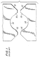
- FIG. 1 there is illustrated a pair of prior art dies 10, 12 of a type utilized to attach a suture to a surgical needle.
- Each die 10 has a working surface at 14 of generally semi-circular shape and adjacent arcuate corner portions 16 to receive limited amounts of excess needle material overflowing during the crimping process.
- the arcuate corner portions 16 are of lesser radii than the working surface and are not concentric therewith as shown.
- the dies are positioned within an apparatus as will be described hereinbelow.
- the apparatus is arranged to cause both dies to simultaneously move toward each other and strike a needle positioned between them. This causes the needle to become elliptical in cross-section and causes portions of the needle to deform into corner portions 16.
- the dies are impacted toward each other, they are separated and the needle is rotated 90°.
- the dies are then struck once again and the attachment is completed.
- the first strike causes the circular aperture in the needle to become elliptical.
- the second strike completes the attachment and reverses the distortion imparted to the needle.
- additional hits are required to secure the suture to the needle. This procedure necessitates at least a dual step attachment which in turn requires additional time and labor.
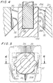
- FIGS. 2-4 there is illustrated a pair of dies 20 constructed according to the present invention.
- Each die 20 is configured to have an inner cavity 22 (FIGS. 2 and 3) which, when combined with the other die of the pair, forms a generally rectangular opening for reception of an end of a needle to be swaged.
- the particular arrangement of the pair of dies 20 is best depicted in the axial view of FIG. 3 in which the dies are shown with a needle 100 therebetween in a position to be attached to a suture 200 (shown in phantom) and the cross-sectional view of FIG. 4 which is taken along lines 4-4 of FIG. 3.
- the dies 20 are shown separated from each other in position prior to impact on a surgical needle 100 having an aperture 110 in which the end portion of suture 200 is positioned (See FIG. 4).
- Each die includes a die face 24, a pair of inner walls 26 perpendicular to the die face 24, and an inner die surface portion 28.
- the dies 20 also have a front surface 20A and an angled rear surface 20B (see Figs. 2 and 4).
- the inner die surfaces 28 each include a substantially planar crimping or swaging surface 30. Swaging surfaces 30 are each angled relative to a plane defined by the die face 24. In particular, as shown in FIG. 4, swaging surfaces 30 gradually taper radially inwardly, relative to needle 100 disposed within the dies, going from the front surface 20A of die 20 to the rear surface 20B of the die 20.
- each swaging surface 30 of a single die 20 defines a plane which is oriented at an angle relative to a plane defined by die face 24.
- orientation of swaging surfaces 30 produces opposed tapered surfaces on the needle end.
- the angle defined by swaging surfaces 30 relative to their respective die faces 26 may range from about 6° to about 15°. In a preferred embodiment, this angle is about 11°.
- inner die surface portion 28 also includes an arcuate-shaped concavity or recess 32.
- Recesses 32 are formed in swaging surfaces 30 and may extend from approximately 1/4 of the length of swaging surface 30 to approximately 3/4 the length of the surface. Recesses 32 define material relief zones to receive needle material displaced by the die 20 when a pair of dies are caused to strike a needle positioned within the generally rectangular-shaped cavity as described above. Recesses 32 are preferably generally arcuate in shape and define a radius of curvature which is generally constant throughout its length. The axis defined by each arcuate recess 32 of die 20 is substantially parallel to the plane defined by its respective die face 24.
- Recesses 32 are each preferably disposed along the midline of swaging surface 30.
- FIGS. 5-6 illustrate the swaging effect dies 20 produce on the drilled needle end.
- the dies 20 are moved towards each other until die faces 24 meet, whereby the swaging surfaces 30 strike the drilled or blunt end portion of needle 100.
- the needle material which is engaged by swaging surfaces 30 accumulates by the swaging action into the relief zone provided by recess 32.
- the apertured portion of the needle will be effectively crimped and attached to the suture by the physical reduction of the dimension of the aperture surrounding the suture.
- the dies of the present invention require only one strike or "hit” to effect attachment of the suture components, thus, eliminating the double-hit method along with its inherent disadvantages.
- the dies are capable of consistently producing detachable needle-suture combinations having pull-out values within the ranges set forth in U.S. Pharmacopeia.
- a further significant advantage of the present die resides in the fact that its particular configuration reduces the criticality of manufacturing the suture components to relatively strict tolerances even when detachable needle-suture attachment is the objective. For example, with conventional crimping procedures for producing detachable needle-suture combinations the suture and needle components often need to be manufactured to a ⁇ 12 ⁇ m (.0005 inch) tolerance in order to achieve proper detachable needle attachment.
- manufacturing tolerances need to be held only to ⁇ 63 ⁇ m (.0025 inch) to provide consistent acceptable detachable needle-suture combinations. This is due to the nature of the crimp formed in the blunt end of the needle. In particular, the depth of the crimp is sufficient to cause the swaged portion of the needle to securely contact and engage the suture even if precise manufacturing tolerances are not met.
- the "ovality" of a suture may present additional difficulties regarding suture attachment.
- Ovality is a term of art that refers to the degree in which the cross-sectional dimension of the suture varies from an exact circular configuration.
- the suture In known crimping processes, the suture must approach a near circular cross-section to achieve proper removable needle suture attachment. This is disadvantageous in that the extra manufacturing processes required to obtain a substantially circular suture are costly and time consuming.
- the ovality of the suture is not as critical as a parameter in achieving acceptable suture attachment since the depth of the crimp formed by the dies is sufficient to securely engage the suture and compensates for any variation in the suture dimensions.
- the needle 100 and suture 200 is positioned within the dies in the manner shown in FIG. 4, i.e., the blunt end surface 120 of needle 100 is aligned with the front end 20A of the dies as shown with the suture 200 inserted within aperture 102 of the needle. Consequently, with this particular positioning of the needle 100 within dies 20, the greatest depth of the crimp caused by the swaging surfaces 30 is provided away from the blunt needle end 120 towards the needle point 130. Accordingly, the tapered surfaces formed on the needle taper inwardly towards the needle point 130.
- die 20 may be modified to accommodate different sized surgical needles.
- dimension "W” of die 20 may be increased or decreased depending on the diameter of the needle end to be received within the die.
- dimension "X" which indicates the depth of the die may also be modified for a particular needle size.
- radius "Z” which indicates the dimension of the radius of curvature of recess 32 may also be varied to accommodate alternative dimensioned needle and suture components.
- Dimension Y which indicates the maximum depth of recess 32 and which is a function of radius "Z” may also be varied.
- the following chart indicates proposed die parameters for various sized surgical needles. (dimensions are in ⁇ m/inches) Needle Size Dim.W. Dim. X Dim.
- the foregoing table illustrates the dimensional characteristics required for detachably connecting a needle of a particular dimension to a suture with the die of the present invention.
- the table is intended to be used only as a guide since the particular dimensions of the die may vary depending on the type and size of the suture being attached as well as the presence of lubricants, etc.
- One skilled in the art may readily determine appropriate dimensions for the die so as to achieve the objectives of the present invention.
- the angular orientation of swaging surfaces may be altered to achieve other desired results as well.
- the die of the present invention is configured in a manner such that the needle is detachably attached to the suture so as to be readily separated by a quick tug provided by the surgeon.
- the die is modified such that the needle is attached with greater pull-out so as to provide a "non-detachable" suture, in which case the suture may be separated from the needle in a more conventional manner, as by cutting with scissors or a scalpel.
- FIGS. 7 and 8 the photomicrographs illustrate the configuration of the needle after the crimping process.
- the dies form a generally arrow-shaped impression on the needle surface.
- the swaging surfaces of the die produce tapered surfaces 36 on the needle.
- the arcuate raised portion 38 present on the needle end reflects the relief zone 32 of the die where the material overflow is received during swaging.
- needle-suture attachment is achieved while maintaining the general symmetry of the needle A with relatively insignificant surface distortion except for the minor impression formed on the surface.
- the needle retains its general circular symmetry in the area of suture attachment which thereby minimizes tissue trauma during the suturing process.
- FIGS. 9 and 10 there is shown an exemplary apparatus 40 on which sutures may be attached to needles utilizing a pair of dies of the present invention.
- the suture attaching machine 40 as illustrated in FIG. 9 includes a table 42 having treadle 44 which is foot operated and connected via treadle rod 46 to suture press 48.
- the treadle 44 is mounted for pivotal movement on pivot rod 50.
- FIG. 11 there is shown a side view of the apparatus shown in FIG. 10.
- the suture press 48 is encircled and is shown in enlarged form in FIG. 11.
- the pair of dies 20 which are constructed according to the invention are positioned within the jaws of the suture press 48 and arranged to be stricken against a needle 100 with the suture 200 in position as shown in FIG. 12.
- the needle 100 shown in FIG. 12 is of a curved type having a straight rear end portion which defines an elongated aperture 110 dimensioned for reception and attachment to an appropriately sized suture 200.
- the needle 100 is supported on a guide support having a "V shaped" guide channel which positively determines and positions the needle location and orientation as shown. Thereafter, appropriate adjustments are made to predetermine the strike force to be transmitted to the needle and suture as may be appropriately calculated to obtain a predetermined pull-out force.
- the treadle is depressed to cause the dies to strike the needle.
- EP-A-591994 An alternative apparatus for attaching surgical sutures to needles is disclosed in EP-A-591994.
- This apparatus includes a frame for positioning and maintaining the needle while the suture is being attached and a die system which selectively impacts the needle to secure the needle thereto.
- the die system may be modified to incorporate the novel dies of the present invention.
- the dies of the present invention are particularly advantageous in that many types of sutures may be readily attached to needles having an aperture in their blunt end, i.e., drilled end needles.
- single strike force is utilized thereby avoiding the need to provide "double-hit" attachment as necessary with prior art dies.
- This procedure provides a suture having a needle which is symmetrical and unaffected by the distorting forces provided by dies and procedures of the prior art.
- the single-hit attachment procedure provides consistent and controlled attachment of the suture and the needle which additionally reduces the time and effort to complete the attachment. Die life is increased, rejected needle/suture attachments are reduced, and attachment time is reduced. As a result the cost of producing a surgical suture is sizably reduced.
- the swaging dies of the present invention may be utilized with all types of needles such as curved needles, straight needles, or the like, provided they have an elongated aperture on their end portion for receiving the suture.
- Sutures usable with the present invention include silk, nylon, linen, cotton, polyester, polypropylene, stainless steel, natural materials such as catgut, synthetic polymers having glycolic acid ester linkages subject to hydrolytic degradation to non-toxic tissue compatible absorbable components, including polyglycolic acid.
- the sutures may be monofilamentary or braided, absorbable or non-absorbable.
- the dies of the present invention are preferably constructed of a hardened material such as tungsten carbide. However, it should be understood that all materials suitable for such die construction may be used, provided the geometric and configurational parameters taught by the present invention are met.
Landscapes
- Health & Medical Sciences (AREA)
- Surgery (AREA)
- Engineering & Computer Science (AREA)
- Life Sciences & Earth Sciences (AREA)
- Medical Informatics (AREA)
- Nuclear Medicine, Radiotherapy & Molecular Imaging (AREA)
- Biomedical Technology (AREA)
- Heart & Thoracic Surgery (AREA)
- Mechanical Engineering (AREA)
- Molecular Biology (AREA)
- Animal Behavior & Ethology (AREA)
- General Health & Medical Sciences (AREA)
- Public Health (AREA)
- Veterinary Medicine (AREA)
- Surgical Instruments (AREA)
- Materials For Medical Uses (AREA)
Claims (11)
- Nadel (100)-Nahtmaterial (200) Kombination, umfassend:a) eine chirurgische Nadel (100), umfassend ein spitzes Ende (130) und ein stumpfes Ende (120) an entgegengesetzten Enden der Nadelachse, wobei das stumpfe Ende eine langgestreckte Öffnung (102) darin begrenzt;b) ein Nahtmaterial (200) mit einem im allgemeinen langgestreckten Endbereich, der innerhalb der langgestreckten Öffnung (102) der Nadel angeordnet ist; undc) einen Bereich (36) des stumpfen Endes, der verformt ist, um eine Anbringung der Nadel an dem Nahtmaterial zu bewirken;
wobei die Nadel-Nahtmaterial-Kombination dadurch gekennzeichnet ist, daß:d) der verformte Bereich zumindest zwei im wesentlichen ebene Oberflächen (36) aufweist, von denen beide winklig relativ zu einer Längsachse versetzt sind, welche durch die langgestreckte Öffnung der Nadel definiert ist, und einen im wesentlichen bogenförmigen erhobenen Bereich (38) besitzt, wobei der verformte Bereich eine Symmetrie um die Nadelachse besitzt und im wesentlichen denselben allgemeinen Querschnittscharakter wie der verbleibende Bereich des stumpfen Endes besitzt, wobei sich der winklige Versatz radial nach innen relativ zur Nadelachse von dem stumpfen Ende der Nadel in Richtung des spitzen Endes verjüngt. - Nadel-Nahtmaterial-Kombination gemäß Anspruch 1, wobei die langgestreckte Öffnung (102) der Nadel einen im allgemeinen kreisförmigen Querschnitt besitzt.
- Nadel-Nahtmaterial-Kombination gemäß Anspruch 1 oder 2, wobei der langgestreckte Endbereich des Nahtmaterials einen kreisförmigen Querschnitt besitzt, der bezüglich der Abmessung der langgestreckten Öffnung der Nadel entspricht.
- Nadel-Nahtmaterial-Kombination gemäß einem der vorhergehenden Ansprüche, wobei der verformte Bereich der Nadel zwei gegenüberliegende, im allgemeinen ebene Oberflächen umfaßt, wobei beide im wesentlichen ebenen Oberflächen einen der im wesentlichen bogenförmigen, angehobenen Bereiche besitzt, der entlang der Mittellinie derselben angeordnet ist.
- Nadel-Nahtmaterial-Kombination gemäß einem der vorhergehenden Ansprüche, wobei das Nahtmaterial lösbar an der Nadel angebracht ist und das Nahtmaterial sofort von der Nadel durch eine vom Benutzer aufgebrachte, vorbestimmte Kraft getrennt werden kann.
- Nadel-Nahtmaterial-Kombination gemäß einem der vorhergehenden Ansprüche, wobei die Nadel aus Edelstahl hergestellt ist.
- Vorrichtung zum Anbringen einer chirurgischen Nadel und eines Nahtmaterials, wobei die Nadel eine Achse besitzt, bei der am einen Ende ein spitzes Ende und an dem anderen Ende ein im allgemeinen zylinderförmiger, stumpfer Endbereich ist, der eine langgestreckte Öffnung mit einem im wesentlichen kreisförmigen Querschnitt begrenzt, wobei das Nahtmaterial einen im allgemeinen langgestreckten Endbereich mit einem im allgemeinen kreisförmigen Querschnitt besitzt, der bezüglich der Abmessung der langgestreckten Öffnung der Nadel entspricht, umfassend ein Paar von Gesenken (20), die beide eine Gesenkfläche (24) mit einem inneren Gesenkflächenbereich (28) aufweisen, wobei jede der inneren Gesenkflächenbereiche eine Biegeoberfläche (30) mit einer bogenförmigen Vertiefung (32), die darin gebildet ist und sich entlang zumindest eines Bereichs der Biegeoberfläche erstreckt, aufweist und die bogenförmige Vertiefung eine Entspannungszone definiert, so daß, wenn der zylinderförmige Endbereich des Nahtmaterials innerhalb der Öffnung der Nadel mit einem Ende des Nahtmaterials hinter der langgestreckten Öffnung aufgenommen positioniert ist, und die Gesenke um den im wesentlichen zylinderförmigen Endbereich der Nadel angeordnet sind, wobei die Verformungsoberflächen im allgemeinen auf die äußere Oberfläche derselben gerichtet sind und eine Symmetrie um die Linie besitzen, welche der Nadelachse entspricht, und das Aufbringen einer nach innen gerichteten Biegekraft auf die Gesenke dazu führt, daß die Gesenke auf die Nadel aufschlagen und nach innen gerichtete Biegekräfte auf gegenüberliegenden Seiten des Nadelendbereichs erzeugen, um die Nadel an dem Nahtmaterial anzubringen, wobei die bogenförmigen Vertiefungen verformtes Material von der Nadel aufnehmen und sammeln, während sie im wesentlichen dieselbe im allgemeinen axiale Querschnittssymmetrie der Nadel in dem durch die Gesenke verformten Bereich beibehalten, und die weiterhin dadurch gekennzeichnet ist, daß die Verformungsoberfläche eine ebene Verformungsoberfläche (30) aufweist, in die die bogenförmige Vertiefung (32) gebildet ist, und die eine Ebene definiert, die relativ zu einer Ebene winklig versetzt ist, welche durch die Gesenkfläche definiert ist, wobei der winklige Versatz sich nach innen relativ zur Achse des Gesenkhohlraums, in dem die Nadel aufgenommen wird, in einer Richtung entsprechend einer Bewegung entlang des zylinderförmigen Endbereichs in Richtung des spitzen Endes verjüngt.
- Vorrichtung gemäß Anspruch 7, wobei die Ebene der Biegeoberfläche einen Winkel definiert, der sich von etwa 6° bis etwa 15° relativ zu der Ebene der Gesenkfläche bewegt.
- Vorrichtung gemäß Anspruch 7 oder 8, wobei die bogenförmige Vertiefung einen Krümmungsradius definiert, der über ihre Länge konstant bleibt.
- Vorrichtung gemäß einem der Ansprüche 7 bis 9, wobei eine von der bogenförmigen Vertiefung definierte Achse im wesentlichen parallel zu der Ebene ist, welche durch die Gesenkfläche definiert ist.
- Vorrichtung gemäß einem der Ansprüche 7 bis 10, wobei die Tiefe der bogenförmigen Vertiefung nach und nach von einem ersten Endbereich des Gesenks zu einem zweiten Endbereich desselben abnimmt.
Applications Claiming Priority (2)
| Application Number | Priority Date | Filing Date | Title |
|---|---|---|---|
| US71653 | 1993-06-02 | ||
| US08/071,653 US5383902A (en) | 1993-06-02 | 1993-06-02 | Surgical needle-suture attachment for controlled suture release |
Publications (3)
| Publication Number | Publication Date |
|---|---|
| EP0627199A2 EP0627199A2 (de) | 1994-12-07 |
| EP0627199A3 EP0627199A3 (de) | 1995-05-31 |
| EP0627199B1 true EP0627199B1 (de) | 1999-07-14 |
Family
ID=22102722
Family Applications (1)
| Application Number | Title | Priority Date | Filing Date |
|---|---|---|---|
| EP94108370A Expired - Lifetime EP0627199B1 (de) | 1993-06-02 | 1994-05-31 | Chirurgische Nadel-Nähfaden-Befestigung zur kontrollierten Trennung des Nähfadens |
Country Status (3)
| Country | Link |
|---|---|
| US (2) | US5383902A (de) |
| EP (1) | EP0627199B1 (de) |
| DE (1) | DE69419457T2 (de) |
Cited By (1)
| Publication number | Priority date | Publication date | Assignee | Title |
|---|---|---|---|---|
| US9192375B2 (en) | 2012-02-29 | 2015-11-24 | Marker Medical, Llc | Surgical apparatus and method |
Families Citing this family (17)
| Publication number | Priority date | Publication date | Assignee | Title |
|---|---|---|---|---|
| US5707391A (en) * | 1995-06-07 | 1998-01-13 | United States Surgical Corporation | Apparatus and method for attaching surgical needle suture components |
| US5722991A (en) * | 1995-06-07 | 1998-03-03 | United States Surgical Corporation | Apparatus and method for attaching surgical needle suture components |
| US5667528A (en) * | 1995-11-22 | 1997-09-16 | United States Surgical Corporation | Braided suture surgical incision member attachment |
| US6001121A (en) * | 1998-04-14 | 1999-12-14 | Ethicon, Inc. | Surgical suture having a thermally formed tip, and apparatus and method for making same |
| US6080183A (en) | 1998-11-24 | 2000-06-27 | Embol-X, Inc. | Sutureless vessel plug and methods of use |
| US6514263B1 (en) | 2000-08-30 | 2003-02-04 | Ethicon Endo-Surgery, Inc. | Helical needle and suture combination having a strain relief element |
| US6613058B1 (en) | 2000-08-30 | 2003-09-02 | Ethicon Endo-Surgery, Inc. | Anastomosis device having needle receiver for capturing the needle |
| US6520973B1 (en) | 2000-08-30 | 2003-02-18 | Ethicon Endo-Surgery, Inc. | Anastomosis device having an improved needle driver |
| US6530932B1 (en) | 2000-08-30 | 2003-03-11 | Ethicon Endo-Surgery, Inc. | Anastomosis device having improved tissue presentation |
| EP1534144B1 (de) | 2002-07-17 | 2011-11-09 | Tyco Healthcare Group LP | Chirurgische Nähnadel |
| US7814630B2 (en) * | 2006-11-17 | 2010-10-19 | Ethicon, Inc. | Apparatus and method for swaging needles |
| US8222564B2 (en) * | 2008-02-13 | 2012-07-17 | Tyco Healthcare Group, Lp | Methods of altering surgical fiber |
| US8214996B2 (en) * | 2008-12-09 | 2012-07-10 | Ethicon, Inc. | Surgical needle swage tool |
| US10431950B2 (en) | 2014-02-18 | 2019-10-01 | Hubbell Incorporated | Smart conductor/connector selecting die |
| US10448947B2 (en) * | 2017-03-22 | 2019-10-22 | Ethicon, Inc. | Swaging systems for attaching surgical needles to sutures having on-press testing of suture attachment strength |
| US10960456B2 (en) | 2017-03-22 | 2021-03-30 | Ethicon, Inc. | Programmable motor driven swaging presses for attaching surgical needles to sutures |
| CN117398142A (zh) * | 2023-10-20 | 2024-01-16 | 北京派尔特医疗科技股份有限公司 | 一种缝合线转接器 |
Family Cites Families (64)
| Publication number | Priority date | Publication date | Assignee | Title |
|---|---|---|---|---|
| US1250114A (en) * | 1916-05-23 | 1917-12-11 | W D Young & Co Inc | Suture. |
| US1578543A (en) * | 1924-08-08 | 1926-03-30 | Titusville Forge Company | Method of making deep-well auger stems |
| US1558037A (en) * | 1925-06-17 | 1925-10-20 | Harry D Morton | Surgical needle and suture assembly and method of making the same |
| US1665216A (en) * | 1925-07-30 | 1928-04-10 | Harry D Morton | Method of making needle-and-suture assembly |
| US1678361A (en) * | 1927-06-25 | 1928-07-24 | Sharp & Smith | Surgical needle |
| US1757129A (en) * | 1928-02-16 | 1930-05-06 | William L Mcclure | Atraumatic rethreadable surgical needle |
| FR661908A (fr) * | 1928-10-09 | 1929-07-31 | Procédé d'obtention de pièces plates devant comporter une portion à section ovale ou analogue dont le grand axe est perpendiculaire au plan des autres portions de lapièce | |
| US2067568A (en) * | 1932-02-08 | 1937-01-12 | Grunthal Moritz | Die for automatically working mechanical forging machines for manufacturing of seamless hollow bodies |
| US2205893A (en) * | 1937-09-03 | 1940-06-25 | Gen Electric | Method of corrugating a heatradiating tube |
| US2411079A (en) * | 1944-09-09 | 1946-11-12 | Gerhard H J Baule | Method of attaching sutures to shanks of surgeons' needles |
| US2620028A (en) * | 1950-03-03 | 1952-12-02 | Loyal T Ives Company Inc | Method of manufacturing surgeons' needles |
| US3055412A (en) * | 1954-07-22 | 1962-09-25 | Burndy Corp | Die assembly for crimping a shielded cable |
| US2983898A (en) * | 1957-10-04 | 1961-05-09 | Malco Mfg Co | Terminal wire crimp and method for forming same |
| US2972781A (en) * | 1957-11-05 | 1961-02-28 | Kahn David Inc | Method of deforming plastic articles |
| US2982395A (en) * | 1958-12-08 | 1961-05-02 | Harbor Boat Building Company | Reusable shipping container |
| US2958929A (en) * | 1959-06-01 | 1960-11-08 | Canada Wire & Cable Co Ltd | Flush ferrule conductor joint |
| US3394704A (en) * | 1965-10-20 | 1968-07-30 | Torrington Co | Surgical needle with bonded suture |
| JPS519926B1 (de) * | 1967-02-04 | 1976-03-31 | ||
| US3643327A (en) * | 1967-06-26 | 1972-02-22 | Thomas & Betts Corp | Method of making a series of electrical connections |
| USRE27735E (en) * | 1969-08-25 | 1973-08-14 | Method for attaching suture needle | |
| US3611551A (en) * | 1969-08-25 | 1971-10-12 | Deknatel Inc | Method for attaching suture and needle |
| US3771343A (en) * | 1972-03-24 | 1973-11-13 | Mc Donnell Douglas Corp | Swaging tool |
| TR17343A (tr) * | 1972-05-31 | 1975-03-24 | Ethicon Inc | Kontrollu olarak serbest birakilabilen suetuer |
| SU471143A2 (ru) * | 1973-01-11 | 1975-05-25 | Центральный Научно-Исследовательский Институт Технологии Машиностроения | Инструмент дл ковки металлов и сплавов |
| US3980177A (en) * | 1973-10-26 | 1976-09-14 | Johnson & Johnson | Controlled release suture |
| AR206516A1 (es) * | 1973-10-26 | 1976-07-30 | Ethicon Inc | Una combinacion de aguja sutura |
| US3972219A (en) * | 1973-11-02 | 1976-08-03 | Robertshaw Controls Company | Apparatus for making the inlet end of a tubular burner construction |
| IN140500B (de) * | 1973-12-26 | 1976-11-20 | Ethicon Inc | |
| US3910282A (en) * | 1974-05-22 | 1975-10-07 | American Cyanamid Co | Needling monofilament sutures |
| US3981307A (en) * | 1974-07-01 | 1976-09-21 | Ethicon, Inc. | Thermal attachment of surgical sutures to needles |
| US3924630A (en) * | 1974-11-18 | 1975-12-09 | Ethicon Inc | Manufacture of controlled release fluid swellable sutures |
| US3963031A (en) * | 1974-12-11 | 1976-06-15 | Ethicon, Inc. | Juncture-lubricated needle-suture combination |
| CA1042638A (en) * | 1975-08-04 | 1978-11-21 | Cedric G. Birks | Swaging dies |
| GB1526221A (en) * | 1975-08-04 | 1978-09-27 | Ccl Systems Ltd | Swaging press |
| US4054144A (en) * | 1976-05-28 | 1977-10-18 | American Cyanamid Company | Short-crimp surgical needle |
| US4027519A (en) * | 1976-09-22 | 1977-06-07 | Thomas & Betts Corporation | Means and method for reducing the perimeter of a hollow thin walled member |
| US4124027A (en) * | 1977-03-04 | 1978-11-07 | Ethicon, Inc. | Controlled release sutures |
| US4192171A (en) * | 1978-03-23 | 1980-03-11 | Automatic Tool Company, Inc. | Hand held crimping tool |
| JPS55100835A (en) * | 1979-01-29 | 1980-08-01 | Matsutani Seisakusho:Kk | Constantly loaded staking apparatus |
| US4292833A (en) * | 1979-06-22 | 1981-10-06 | Lapp Ellsworth W | Crimping tool |
| JPS5615731A (en) * | 1979-07-20 | 1981-02-16 | Olympus Optical Co | Manufacture of cell diagnosing brush |
| JPS58221902A (ja) * | 1982-06-20 | 1983-12-23 | 日本精工株式会社 | バツクルとワイヤ−との加締方法 |
| US4567650A (en) * | 1984-04-09 | 1986-02-04 | Automation Industries, Inc. | Fiber optic crimping tool |
| AU584891B2 (en) * | 1984-04-19 | 1989-06-08 | E.I. Du Pont De Nemours And Company | Optical fiber material having optical fiber tightly held by wrapping material |
| US4890614A (en) * | 1986-02-19 | 1990-01-02 | Yasuo Nakamura | Suture needle and its manufacturing process |
| EP0232444A1 (de) * | 1986-02-19 | 1987-08-19 | Yasuo Nakamura | Chirurgische Nähnadel und Verfahren zur Herstellung |
| SE8602301D0 (sv) * | 1986-05-21 | 1986-05-21 | Weidmueller C A Gmbh Co | Kabelskoverktyg |
| KR950000058B1 (ko) * | 1986-06-12 | 1995-01-09 | 가부시끼가이샤 뮤텍크 | 실이 달린 봉합침과 그 제조방법 |
| US4722384A (en) * | 1986-09-29 | 1988-02-02 | Matsutani Seisakusho Co., Ltd. | Method of and apparatus for attaching suture to operating needle |
| JPS63212028A (ja) * | 1987-02-26 | 1988-09-05 | Matsutani Seisakusho:Kk | アイレス針の糸取付装置 |
| US4935029A (en) * | 1987-06-22 | 1990-06-19 | Matsutani Seisakusho Co., Ltd. | Surgical needle |
| JPS6466838A (en) * | 1987-09-04 | 1989-03-13 | Brother Ind Ltd | Optical reader |
| DE8715099U1 (de) * | 1987-11-13 | 1988-02-04 | C. Hessing KG Industrie-Erzeugnisse, 7570 Baden-Baden | Preßwerkzeug zur Herstellung einer Preßmuffenverbindung für Hochofenbrennrohre |
| JPH01317430A (ja) * | 1988-06-18 | 1989-12-22 | Keisei Ika Kogyo Kk | 手術用縫合針の組立装置 |
| JPH0390237A (ja) * | 1989-08-31 | 1991-04-16 | Matsutani Seisakusho Co Ltd | アイレス縫合針の加工方法 |
| US5131131A (en) * | 1989-11-03 | 1992-07-21 | United States Surgical Corporation | Method for attaching surgical suture components |
| US5046350A (en) * | 1989-11-03 | 1991-09-10 | United States Surgical Corporation | Apparatus for attaching surgical suture components |
| US5168619A (en) * | 1989-11-03 | 1992-12-08 | United States Surgical Corporation | Method for attaching surgical suture components |
| US5099676A (en) * | 1989-11-03 | 1992-03-31 | United States Surgical Corporation | Apparatus for attaching surgical suture components |
| US5084963A (en) * | 1990-09-28 | 1992-02-04 | Burndy Corporation | Preconnection deforming die and method of connecting a grounding rod with an electrical cable |
| US5201760A (en) * | 1990-12-24 | 1993-04-13 | American Cyanamid Company | Surgical needle-suture combination and apparatus and method for attaching the same |
| US5207701A (en) * | 1990-12-24 | 1993-05-04 | American Cyanamid Company | Surgical needle-suture combination, and apparatus and method for attaching the same |
| US5224955A (en) * | 1991-08-15 | 1993-07-06 | American Cyanamid Company | Surgical needle-suture combination and apparatus and method for attaching the same |
| US5230352A (en) * | 1992-03-04 | 1993-07-27 | American Cyanamid Company | Medical suturing device, a single-strike die mechanism, and a method of using said die mechanism for forming the medical suturing device |
-
1993
- 1993-06-02 US US08/071,653 patent/US5383902A/en not_active Expired - Lifetime
-
1994
- 1994-05-31 EP EP94108370A patent/EP0627199B1/de not_active Expired - Lifetime
- 1994-05-31 DE DE69419457T patent/DE69419457T2/de not_active Expired - Lifetime
- 1994-10-20 US US08/326,554 patent/US5568746A/en not_active Expired - Lifetime
Cited By (2)
| Publication number | Priority date | Publication date | Assignee | Title |
|---|---|---|---|---|
| US9192375B2 (en) | 2012-02-29 | 2015-11-24 | Marker Medical, Llc | Surgical apparatus and method |
| US9572566B2 (en) | 2012-02-29 | 2017-02-21 | Marker Medical, Llc | Surgical suturing apparatus and method |
Also Published As
| Publication number | Publication date |
|---|---|
| EP0627199A2 (de) | 1994-12-07 |
| EP0627199A3 (de) | 1995-05-31 |
| US5568746A (en) | 1996-10-29 |
| US5383902A (en) | 1995-01-24 |
| DE69419457D1 (de) | 1999-08-19 |
| DE69419457T2 (de) | 1999-11-25 |
Similar Documents
| Publication | Publication Date | Title |
|---|---|---|
| US5722991A (en) | Apparatus and method for attaching surgical needle suture components | |
| US5568746A (en) | Surgical needle-suture attachment for controlled suture release | |
| CA2055820C (en) | Loop threaded combined surgical needle-suture device | |
| US5099676A (en) | Apparatus for attaching surgical suture components | |
| US3910282A (en) | Needling monofilament sutures | |
| US5913875A (en) | Taper point needle | |
| US6322581B1 (en) | Suturing needle for medical use | |
| US4072041A (en) | Short-crimp surgical needle | |
| CA2475922C (en) | Implant plate, method and facility for the manufacure thereof | |
| US3160157A (en) | Surgical needle | |
| DE69433211T2 (de) | Knochenfixiervorrichtung | |
| EP0580994B1 (de) | Aus dehnbarem, bioabsorbierbarem Kunststoff hergestellte Klammer mit verknoteter Konfiguration sowie Verfahren und Gerät zu deren Verformung | |
| US20100146770A1 (en) | Method of manufacturing a barbed surgical suture | |
| US5116358A (en) | Combined surgical needle-suture device possessing a controlled suture separation feature | |
| US5201760A (en) | Surgical needle-suture combination and apparatus and method for attaching the same | |
| EP0121362A1 (de) | Spaltring zum Vernähen von Geweben | |
| US5046350A (en) | Apparatus for attaching surgical suture components | |
| EP0597260A2 (de) | Nadel mit echtem Doppel-T-Querschnitt | |
| US5403345A (en) | Needle suture attachment | |
| JPH0560746B2 (de) | ||
| JP2007125417A (ja) | 医用縫合具、一度打ち型機構及び医用縫合具を形成するための前記型機構の使用方法 | |
| US5707391A (en) | Apparatus and method for attaching surgical needle suture components | |
| US5041128A (en) | Combined surgical needle-suture device possessing an integrated suture cut-off feature | |
| US5168619A (en) | Method for attaching surgical suture components | |
| US5207701A (en) | Surgical needle-suture combination, and apparatus and method for attaching the same |
Legal Events
| Date | Code | Title | Description |
|---|---|---|---|
| PUAI | Public reference made under article 153(3) epc to a published international application that has entered the european phase |
Free format text: ORIGINAL CODE: 0009012 |
|
| AK | Designated contracting states |
Kind code of ref document: A2 Designated state(s): DE ES FR GB IT |
|
| RIN1 | Information on inventor provided before grant (corrected) |
Inventor name: GIORDANO, GIUSEPPE Inventor name: BELCOURT, RONALD H., JR. Inventor name: COLLIGAN, FRANCIS D. Inventor name: CARPENTIERE, RICHARD P. |
|
| PUAL | Search report despatched |
Free format text: ORIGINAL CODE: 0009013 |
|
| AK | Designated contracting states |
Kind code of ref document: A3 Designated state(s): DE ES FR GB IT |
|
| 17P | Request for examination filed |
Effective date: 19951002 |
|
| 17Q | First examination report despatched |
Effective date: 19970905 |
|
| GRAG | Despatch of communication of intention to grant |
Free format text: ORIGINAL CODE: EPIDOS AGRA |
|
| GRAG | Despatch of communication of intention to grant |
Free format text: ORIGINAL CODE: EPIDOS AGRA |
|
| GRAH | Despatch of communication of intention to grant a patent |
Free format text: ORIGINAL CODE: EPIDOS IGRA |
|
| GRAH | Despatch of communication of intention to grant a patent |
Free format text: ORIGINAL CODE: EPIDOS IGRA |
|
| GRAA | (expected) grant |
Free format text: ORIGINAL CODE: 0009210 |
|
| RIN1 | Information on inventor provided before grant (corrected) |
Inventor name: GIORDANO, GIUSEPPE Inventor name: BELCOURT, RONALD H., JR. Inventor name: COLLIGAN, FRANCIS D. Inventor name: CARPENTIERE, RICHARD P. |
|
| AK | Designated contracting states |
Kind code of ref document: B1 Designated state(s): DE ES FR GB IT |
|
| PG25 | Lapsed in a contracting state [announced via postgrant information from national office to epo] |
Ref country code: IT Free format text: LAPSE BECAUSE OF FAILURE TO SUBMIT A TRANSLATION OF THE DESCRIPTION OR TO PAY THE FEE WITHIN THE PRE;WARNING: LAPSES OF ITALIAN PATENTS WITH EFFECTIVE DATE BEFORE 2007 MAY HAVE OCCURRED AT ANY TIME BEFORE 2007. THE CORRECT EFFECTIVE DATE MAY BE DIFFERENT FROM THE ONE RECORDED.SCRIBED TIME-LIMIT Effective date: 19990714 Ref country code: ES Free format text: THE PATENT HAS BEEN ANNULLED BY A DECISION OF A NATIONAL AUTHORITY Effective date: 19990714 |
|
| REF | Corresponds to: |
Ref document number: 69419457 Country of ref document: DE Date of ref document: 19990819 |
|
| ET | Fr: translation filed | ||
| PLBE | No opposition filed within time limit |
Free format text: ORIGINAL CODE: 0009261 |
|
| STAA | Information on the status of an ep patent application or granted ep patent |
Free format text: STATUS: NO OPPOSITION FILED WITHIN TIME LIMIT |
|
| 26N | No opposition filed | ||
| REG | Reference to a national code |
Ref country code: GB Ref legal event code: IF02 |
|
| PGFP | Annual fee paid to national office [announced via postgrant information from national office to epo] |
Ref country code: GB Payment date: 20130528 Year of fee payment: 20 Ref country code: DE Payment date: 20130530 Year of fee payment: 20 |
|
| PGFP | Annual fee paid to national office [announced via postgrant information from national office to epo] |
Ref country code: FR Payment date: 20130606 Year of fee payment: 20 |
|
| REG | Reference to a national code |
Ref country code: DE Ref legal event code: R071 Ref document number: 69419457 Country of ref document: DE |
|
| REG | Reference to a national code |
Ref country code: GB Ref legal event code: PE20 Expiry date: 20140530 |
|
| PG25 | Lapsed in a contracting state [announced via postgrant information from national office to epo] |
Ref country code: GB Free format text: LAPSE BECAUSE OF EXPIRATION OF PROTECTION Effective date: 20140530 |
|
| PG25 | Lapsed in a contracting state [announced via postgrant information from national office to epo] |
Ref country code: DE Free format text: LAPSE BECAUSE OF EXPIRATION OF PROTECTION Effective date: 20140603 |