EP0627232A2 - Steckverbindung - Google Patents
Steckverbindung Download PDFInfo
- Publication number
- EP0627232A2 EP0627232A2 EP94104752A EP94104752A EP0627232A2 EP 0627232 A2 EP0627232 A2 EP 0627232A2 EP 94104752 A EP94104752 A EP 94104752A EP 94104752 A EP94104752 A EP 94104752A EP 0627232 A2 EP0627232 A2 EP 0627232A2
- Authority
- EP
- European Patent Office
- Prior art keywords
- plug
- sterile
- line
- film
- plug connection
- Prior art date
- Legal status (The legal status is an assumption and is not a legal conclusion. Google has not performed a legal analysis and makes no representation as to the accuracy of the status listed.)
- Withdrawn
Links
Images


Classifications
-
- A—HUMAN NECESSITIES
- A61—MEDICAL OR VETERINARY SCIENCE; HYGIENE
- A61B—DIAGNOSIS; SURGERY; IDENTIFICATION
- A61B17/00—Surgical instruments, devices or methods
-
- A—HUMAN NECESSITIES
- A61—MEDICAL OR VETERINARY SCIENCE; HYGIENE
- A61B—DIAGNOSIS; SURGERY; IDENTIFICATION
- A61B90/00—Instruments, implements or accessories specially adapted for surgery or diagnosis and not covered by any of the groups A61B1/00 - A61B50/00, e.g. for luxation treatment or for protecting wound edges
- A61B90/40—Apparatus fixed or close to patients specially adapted for providing an aseptic surgical environment
-
- A—HUMAN NECESSITIES
- A61—MEDICAL OR VETERINARY SCIENCE; HYGIENE
- A61M—DEVICES FOR INTRODUCING MEDIA INTO, OR ONTO, THE BODY; DEVICES FOR TRANSDUCING BODY MEDIA OR FOR TAKING MEDIA FROM THE BODY; DEVICES FOR PRODUCING OR ENDING SLEEP OR STUPOR
- A61M39/00—Tubes, tube connectors, tube couplings, valves, access sites or the like, specially adapted for medical use
- A61M39/10—Tube connectors or tube couplings
- A61M39/14—Tube connectors or tube couplings for connecting tubes having sealed ends
-
- G—PHYSICS
- G02—OPTICS
- G02B—OPTICAL ELEMENTS, SYSTEMS OR APPARATUS
- G02B6/00—Light guides; Structural details of arrangements comprising light guides and other optical elements, e.g. couplings
- G02B6/24—Coupling light guides
- G02B6/36—Mechanical coupling means
- G02B6/38—Mechanical coupling means having fibre to fibre mating means
- G02B6/3807—Dismountable connectors, i.e. comprising plugs
- G02B6/381—Dismountable connectors, i.e. comprising plugs of the ferrule type, e.g. fibre ends embedded in ferrules, connecting a pair of fibres
- G02B6/3817—Dismountable connectors, i.e. comprising plugs of the ferrule type, e.g. fibre ends embedded in ferrules, connecting a pair of fibres containing optical and electrical conductors
-
- G—PHYSICS
- G02—OPTICS
- G02B—OPTICAL ELEMENTS, SYSTEMS OR APPARATUS
- G02B6/00—Light guides; Structural details of arrangements comprising light guides and other optical elements, e.g. couplings
- G02B6/24—Coupling light guides
- G02B6/36—Mechanical coupling means
- G02B6/38—Mechanical coupling means having fibre to fibre mating means
- G02B6/3807—Dismountable connectors, i.e. comprising plugs
- G02B6/3833—Details of mounting fibres in ferrules; Assembly methods; Manufacture
- G02B6/3847—Details of mounting fibres in ferrules; Assembly methods; Manufacture with means preventing fibre end damage, e.g. recessed fibre surfaces
- G02B6/3849—Details of mounting fibres in ferrules; Assembly methods; Manufacture with means preventing fibre end damage, e.g. recessed fibre surfaces using mechanical protective elements, e.g. caps, hoods, sealing membranes
-
- A—HUMAN NECESSITIES
- A61—MEDICAL OR VETERINARY SCIENCE; HYGIENE
- A61B—DIAGNOSIS; SURGERY; IDENTIFICATION
- A61B17/00—Surgical instruments, devices or methods
- A61B17/00234—Surgical instruments, devices or methods for minimally invasive surgery
-
- A—HUMAN NECESSITIES
- A61—MEDICAL OR VETERINARY SCIENCE; HYGIENE
- A61B—DIAGNOSIS; SURGERY; IDENTIFICATION
- A61B18/00—Surgical instruments, devices or methods for transferring non-mechanical forms of energy to or from the body
- A61B18/04—Surgical instruments, devices or methods for transferring non-mechanical forms of energy to or from the body by heating
- A61B18/12—Surgical instruments, devices or methods for transferring non-mechanical forms of energy to or from the body by heating by passing a current through the tissue to be heated, e.g. high-frequency current
- A61B18/14—Probes or electrodes therefor
-
- A—HUMAN NECESSITIES
- A61—MEDICAL OR VETERINARY SCIENCE; HYGIENE
- A61B—DIAGNOSIS; SURGERY; IDENTIFICATION
- A61B17/00—Surgical instruments, devices or methods
- A61B2017/0046—Surgical instruments, devices or methods with a releasable handle; with handle and operating part separable
-
- A—HUMAN NECESSITIES
- A61—MEDICAL OR VETERINARY SCIENCE; HYGIENE
- A61B—DIAGNOSIS; SURGERY; IDENTIFICATION
- A61B2217/00—General characteristics of surgical instruments
- A61B2217/002—Auxiliary appliance
- A61B2217/005—Auxiliary appliance with suction drainage system
-
- A—HUMAN NECESSITIES
- A61—MEDICAL OR VETERINARY SCIENCE; HYGIENE
- A61M—DEVICES FOR INTRODUCING MEDIA INTO, OR ONTO, THE BODY; DEVICES FOR TRANSDUCING BODY MEDIA OR FOR TAKING MEDIA FROM THE BODY; DEVICES FOR PRODUCING OR ENDING SLEEP OR STUPOR
- A61M1/00—Suction or pumping devices for medical purposes; Devices for carrying-off, for treatment of, or for carrying-over, body-liquids; Drainage systems
- A61M1/71—Suction drainage systems
-
- A—HUMAN NECESSITIES
- A61—MEDICAL OR VETERINARY SCIENCE; HYGIENE
- A61M—DEVICES FOR INTRODUCING MEDIA INTO, OR ONTO, THE BODY; DEVICES FOR TRANSDUCING BODY MEDIA OR FOR TAKING MEDIA FROM THE BODY; DEVICES FOR PRODUCING OR ENDING SLEEP OR STUPOR
- A61M39/00—Tubes, tube connectors, tube couplings, valves, access sites or the like, specially adapted for medical use
- A61M39/10—Tube connectors or tube couplings
- A61M2039/1027—Quick-acting type connectors
-
- A—HUMAN NECESSITIES
- A61—MEDICAL OR VETERINARY SCIENCE; HYGIENE
- A61M—DEVICES FOR INTRODUCING MEDIA INTO, OR ONTO, THE BODY; DEVICES FOR TRANSDUCING BODY MEDIA OR FOR TAKING MEDIA FROM THE BODY; DEVICES FOR PRODUCING OR ENDING SLEEP OR STUPOR
- A61M3/00—Medical syringes, e.g. enemata; Irrigators
- A61M3/02—Enemata; Irrigators
-
- A—HUMAN NECESSITIES
- A61—MEDICAL OR VETERINARY SCIENCE; HYGIENE
- A61M—DEVICES FOR INTRODUCING MEDIA INTO, OR ONTO, THE BODY; DEVICES FOR TRANSDUCING BODY MEDIA OR FOR TAKING MEDIA FROM THE BODY; DEVICES FOR PRODUCING OR ENDING SLEEP OR STUPOR
- A61M3/00—Medical syringes, e.g. enemata; Irrigators
- A61M3/02—Enemata; Irrigators
- A61M3/0279—Cannula; Nozzles; Tips; their connection means
-
- G—PHYSICS
- G02—OPTICS
- G02B—OPTICAL ELEMENTS, SYSTEMS OR APPARATUS
- G02B6/00—Light guides; Structural details of arrangements comprising light guides and other optical elements, e.g. couplings
- G02B6/24—Coupling light guides
- G02B6/36—Mechanical coupling means
- G02B6/38—Mechanical coupling means having fibre to fibre mating means
- G02B6/3807—Dismountable connectors, i.e. comprising plugs
- G02B6/381—Dismountable connectors, i.e. comprising plugs of the ferrule type, e.g. fibre ends embedded in ferrules, connecting a pair of fibres
-
- G—PHYSICS
- G02—OPTICS
- G02B—OPTICAL ELEMENTS, SYSTEMS OR APPARATUS
- G02B6/00—Light guides; Structural details of arrangements comprising light guides and other optical elements, e.g. couplings
- G02B6/24—Coupling light guides
- G02B6/36—Mechanical coupling means
- G02B6/38—Mechanical coupling means having fibre to fibre mating means
- G02B6/3807—Dismountable connectors, i.e. comprising plugs
- G02B6/3833—Details of mounting fibres in ferrules; Assembly methods; Manufacture
- G02B6/3847—Details of mounting fibres in ferrules; Assembly methods; Manufacture with means preventing fibre end damage, e.g. recessed fibre surfaces
-
- Y—GENERAL TAGGING OF NEW TECHNOLOGICAL DEVELOPMENTS; GENERAL TAGGING OF CROSS-SECTIONAL TECHNOLOGIES SPANNING OVER SEVERAL SECTIONS OF THE IPC; TECHNICAL SUBJECTS COVERED BY FORMER USPC CROSS-REFERENCE ART COLLECTIONS [XRACs] AND DIGESTS
- Y10—TECHNICAL SUBJECTS COVERED BY FORMER USPC
- Y10S—TECHNICAL SUBJECTS COVERED BY FORMER USPC CROSS-REFERENCE ART COLLECTIONS [XRACs] AND DIGESTS
- Y10S604/00—Surgery
- Y10S604/905—Aseptic connectors or couplings, e.g. frangible, piercable
Definitions
- the invention relates to a plug connection for connecting at least one sterile electrical, optical and / or fluid-carrying line to at least one non-sterile device, each with a line-side and a device-side connector part.
- connection lines are fed to the patient via a central connection panel which is located within the sterile operating area.
- the connection of the connection lines to the connection panel is carried out together with one or more multiple plug connections, whereby no contact with sterile equipment components in the sterile OR area and sterile OR personnel is permitted.
- This sterile connection panel is covered with a sterile cover (tubular bag) by auxiliary personnel to maintain sterility before swiveling into the sterile operating area.
- the sterile connection lines must be connected to the central connection field with the sterile plugs while maintaining sterility by sterile operating personnel. To connect the multiple plug connections, it is necessary to cut out suitable openings in the connection area from the sterile cover.
- the invention has for its object to realize an easy-to-use plug connection with different types of connecting lines, with which these lines can be connected to sterile conditions within the sterile surgical area to non-sterile devices, whereby no unsterile surfaces are exposed during the connection process.
- the plug connection By means of the plug connection, sterile and non-sterile parts remain hermetically separated from one another, in particular even during the plug-in process, the plug-in process itself being easy to carry out with one hand.
- the non-sterile plug part on the device side including the lines running thereon and to be contacted in the sterile operating area (and possibly also the device itself) is surrounded by a sterile film.
- An opening in the plug area for the connection is then exposed in the film by means of a separating or cutting device.
- the cut-out film is discharged into the interior of the plug, so that the connection between the lines to be contacted can then be carried out and the plug connection as a whole can be locked.
- All functional parts for the separating and cutting device and the individual plug elements of the lines to be connected are located within the closed, preferably circular sealing lip, so that after penetration of the film there is no open connection from the non-sterile device-side plug part to the sterile line-side plug area. This seal also protects the inner connector area from external contamination.
- FIGS. 1 to d each has a non-sterile plug part 1 on the device side and a sterile plug part 2 on the line side. Both plug parts are separated from one another by a sterile film 3 before the plugging process, the film separating the non-sterile device part protruding into the OR from the sterile area of the OR field in the further and not shown area.
- Both connector parts 1 and 2 each have mutually fitting, spring-mounted sealing and clamping rings 1.1 and 2.1, which surround the contact field of the lines 1.3, 1.4 and 2.3, 2.4 to be contacted.
- the line 1.3 and 2.3 to be plugged in is a fluid-carrying line, e.g. around a suction line connected to a vacuum pump and with line 1.4 or 2.4 around an insulated electrical contact line. Whether and how such different types of cables are combined in a connector and their number depends, however, in particular on safety considerations.
- the film 3 is clamped between the sealing and clamping rings 1.1 and 2.1 and by a spinous process 2.51, which is arranged at the tip of a plunger 2.5 in the center of the right connector part , perforated.
- the thus clamped and stretched film 3 is tensioned by a further insertion of the right connector part 2 by a ring 2.6 running concentrically to the sealing and clamping ring 2.1 and pressed against a cutting ring 1.6 running concentrically to the sealing and clamping ring 1.1, which is fitted with knives 1.61 ( see Figure 1 c).
- the plug element 2.7 of the plug part 2 carrying the contacts 2.3 and 2.4 to be plugged is axially displaceable in a guide of the plug element 2.2 and becomes further
- the course of the plugging process is pushed against the center piece 1.2 of the plug part 1, as a result of which the lines to be plugged in connect.
- a catch 2.8 on the plug element 2.7 engages in a corresponding groove 2.9 of the plug element 2.2, which in turn is firmly connected to the plug part 1 or 1.2 on the device side by a bayonet lock.
- the locking device 2.8 is released, then the plug element 2.7 is withdrawn and finally the bayonet locking of the plug element 2.2 is released from the plug part 1 by rotation. At the same time, the film piece 3.1 hanging on the spinous process 2.51 is pulled out of the opening 1.5 and can thus be removed.
- the plug part 2 can be further broken down into the elements 2.2 and 2.7 by lifting the locking and anti-rotation device 2.21 and pulling the plug element 2.7 out of the guide of the plug element 2.2. Furthermore, the sealing and clamping ring 2.1 held by the spring 2.11 can be removed.
- the attachment of the plug contacts 1.3, 1.4 and 2.3, 2.4 in the respective connector elements 1 and 2 is designed so that in the event of malfunctions the individual connections can be changed under sterile conditions by removing them on the back of the connector and replacing them with new connector contacts; as long as such a contact change does not take place simultaneously on both connector parts 1 and 2, the separation between the non-sterile and sterile area is maintained.
- a circular heating wire can alternatively be installed, which cuts out the film from the contact area by briefly heating during the plugging process.
- the film can also be sucked off by a suction device via the channel 1.5.
- a transparent, stretchable material with a thickness between 50 and 100 ⁇ m is particularly suitable as the film.
- two device-side connector parts 21.1 and 21.2 are arranged in the manner of the embodiment according to FIG. 1 on a connection panel 20, the lines 23.1 to 23.4 to be plugged in each case being led via a shaft 50 to the devices located in the non-sterile area will.
- the entire connection panel, including the shaft 50, is surrounded by a film bag 30, which represents the separation between the sterile and the non-sterile area.
- Corresponding plug parts 22.1 and 22.2 in the embodiment described under FIG. 1 can be connected to the plug parts 21.1 and 21.2 arranged in the connection field.
- the lines 24.1, 24.2, 24.3 and 24.4 arranged on these plug parts 22.1 and 22.2 lead to the sterile operating field.
Landscapes
- Health & Medical Sciences (AREA)
- Life Sciences & Earth Sciences (AREA)
- Physics & Mathematics (AREA)
- Heart & Thoracic Surgery (AREA)
- Surgery (AREA)
- Engineering & Computer Science (AREA)
- Public Health (AREA)
- Biomedical Technology (AREA)
- Veterinary Medicine (AREA)
- Animal Behavior & Ethology (AREA)
- General Health & Medical Sciences (AREA)
- General Physics & Mathematics (AREA)
- Optics & Photonics (AREA)
- Molecular Biology (AREA)
- Medical Informatics (AREA)
- Nuclear Medicine, Radiotherapy & Molecular Imaging (AREA)
- Pulmonology (AREA)
- Anesthesiology (AREA)
- Hematology (AREA)
- Pathology (AREA)
- Oral & Maxillofacial Surgery (AREA)
- Infusion, Injection, And Reservoir Apparatuses (AREA)
- External Artificial Organs (AREA)
Abstract
Description
- Die Erfindung betrifft eine Steckverbindung zum Anschluß mindestens einer sterilen elektrischen, optischen und/oder fluidführenden Leitung an mindestens ein unsteriles Gerät mit jeweils einem leitungsseitigen und einem geräteseitigen Steckerteil.
- In den verschiedenen Anwendungsbereichen der Chirurgie ist es notwendig, innerhalb des sterilen OP-Bereiches Steckverbindungen zwischen Verbindungsleitungen vom Patienten zu technischen Versorgungseinrichtungen und umgekehrt herzustellen. Insbesondere bei der minimalinvasiven Chirurgie sind mehrere unterschiedliche Hilfsgeräte für die Präparation des OP-Feldes und den Chirurgieeingriff notwendig, bei denen Verbindungen mittels Schläuche und Kabel hergestellt werden müssen.
- Bei einem in der älteren Anmeldung P 42 42 069.5 beschriebenen Arbeitsplatz-System wird zur Optimierung des Behandlungsablaufs die Zuführung der Verbindungsleitungen zum Patienten über ein zentrales Anschlußfeld durchgeführt, das sich innerhalb des sterilen OP-Bereiches befindet. Der Anschluß der Verbindungsleitungen am Anschlußfeld erfolgt zusammengefaßt mit einer oder mehreren Mehrfach-Steckverbindungen, wobei keine Berührung mit sterilen apparativen Komponenten im sterilen OP-Bereich und sterilem OP-Personal erfolgen darf. Dieses sterile Anschlußfeld wird zur Einhaltung der Sterilität vor dem Einschwenken in den sterilen OP-Bereich vom Hilfspersonal mit einer Sterilabdeckung (Schlauchbeutel) überzogen. Nach dem Einschwenken des Anschlußfeldes müssen die sterilen Verbindungsleitungen mit den sterilen Steckern unter Einhaltung der Sterilität durch steriles OP-Personal an dem zentralen Anschlußfeld konnektiert werden. Zur Konnektierung der Mehrfach-Steckverbindungen ist es notwendig, im Anschlußbereich aus der Sterilabdeckung passende Öffnungen herauszuschneiden.
- Der Erfindung liegt die Aufgabe zugrunde, eine einfach zu handhabende Steckverbindung mit unterschiedlichen Typen von Verbindungsleitungen zu realisieren, mit dem diese Leitungen unter Sterilbedingungen innerhalb des sterilen OP-Bereiches an unsterile Geräte angeschlossen werden können, wobei während des Anschlußvorganges keinerlei unsterile Flächen freigelegt werden.
- Diese Aufgabe erfüllt eine nach den Merkmalen des Patentanspruchs 1 ausgebildete Steckvorrichtung.
- Mittels der Steckverbindung bleiben sterile und unsterile Teile insbesondere auch während des Steckvorganges hermetisch voneinander getrennt, wobei der Steckvorgang selbst leicht mit einer Hand durchzuführen ist. Hierzu ist der unsterile, geräteseitige Steckerteil einschließlich der daran befindlichen im sterilen OP-Bereich verlaufenden und zu kontaktierenden Leitungen (ggf. auch das Gerät selbst) von einer sterilen Folie umgeben. Das im sterilen OP-Bereich gelegene, mit zum Patienten führende Leitungen versehene Steckerteil bewirkt vor dem Einstecken in das geräteseitige Stekkerteil mit diesem eine Abdichtung des Kontaktbereiches durch Einklemmen der Folie zwischen zwei korrespondierende Dicht- und Klemmränder beider Steckerteile. Anschließend wird mittels einer Trenn-oder Schneidvorrichtung in der Folie eine Öffnung des Steckerbereiches für den Anschluß freigelegt. Die ausgeschnittene Folie wird in den Innenbereich des Steckers abgeführt, so daß anschließend die Verbindung zwischen den zu kontaktierenden Leitungen durchgeführt und die Steckverbindung als Ganzes arretiert werden kann.
- Alle Funktionsteile für die Trenn- und Schneidvorrichtung sowie die einzelnen Steckerelemente der zu verbindenden Leitungen befinden sich innerhalb der geschlossenen, vorzugsweise kreisförmigen Dichtlippe, so daß nach der Penetration der Folie keine offene Verbindung von dem unsterilen geräteseitigen Steckerteil zum sterilen leitungsseitigen Steckerbereich besteht. Diese Dichtung schützt zusätzlich auch den inneren Steckerbereich vor Verschmutzungen von außen.
- Die Erfindung wird im folgenden anhand eines in den Figuren teilweise schematisch dargestellten Ausführungsbeispieles näher beschrieben.
- Es zeigen:
- Fig. 1 a bis 1 d einen Querschnitt durch eine Steckverbindung in vier Phasen des Steckvorganges
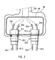
- Fig. 2 ein Anschlußfeld mit mehreren sterilen Steckverbindungen.
- Das in den Figuren 1 bis d dargestellte Ausführungsbeispiel weist jeweils ein geräteseitiges unsteriles Steckerteil 1 sowie ein leitungsseitiges, steriles Steckerteil 2 auf. Beide Steckerteile sind vor dem Steckvorgang durch eine sterile Folie 3 voneinander getrennt, wobei die Folie Im weiteren und nicht dargestellten Bereich den in den OP hineinragenden unsterilen Geräteteil von dem sterilen Bereich des OP-Feldes trennt. Beide Steckerteile 1 und 2 weisen jeweils aufeinanderpassende, federnd gelagerte Dicht- und Klemmringe 1.1 und 2.1 auf, welche das Kontaktfeld der zu kontaktierenden Leitungen 1.3, 1.4 bzw. 2.3, 2.4 umgeben.
- Im dargestellten Ausführungsbeispiel handelt es sich bei der zu steckenden Leitung 1.3 und 2.3 um eine fluidführende Leitung, z.B. um eine mit einer Vakuumpumpe verbundene Absaugleitung und bei der Leitung 1.4 bzw. 2.4 um eine isolierte elektrische Kontaktleitung. Ob und in welcher Weise solche unterschiedlichen Leitungsarten in einem Stekker kombiniert werden sowie deren Anzahl, hängt jedoch insbesondere von sicherheitstechnischen Überlegungen ab.
- Mit der ersten, in Fig. 1 gezeigten Berührung der beiden Steckerteile 1 und 2 wird die Folie 3 zwischen den Dicht- und Klemmringen 1.1 und 2.1 eingeklemmt sowie von einem Dornfortsatz 2.51, der an der Spitze eines Stößels 2.5 im Zentrum des rechten Steckerteiles angeordnet ist, perforiert. Die so eingeklemmte und gespannte Folie 3 wird bei weiterem Einschieben des rechten Steckerteiles 2 durch einen konzentrisch zum Dicht- und Klemmring 2.1 verlaufenden Ring 2.6 gespannt und an ein konzentrisch zum Dicht- und Klemmring 1.1 verlaufenden Schneidring 1.6 gedrückt, welcher mit Messern 1.61 besetzt ist (siehe Figur 1 c). Bei Erreichen einer vorbestimmten Position des einfedernden Dicht- und Klemmringes 1.1 löst dieser über einen nicht dargestellten Schalter einen , ebenfalls nicht dargestellten elektrischen Antrieb für den Schneidring 1.6 aus, wodurch dieser in Drehung versetzt wird und aus der Folie 3 den innerhalb des Dicht- und Klemmränder 1.1 und 2.1 gelegenen Bereich herausschneidet. Das herausgeschnittene Folienstück 3.1 wird durch den Stößel 2.5 in eine zentrale Bohrung 1.5 des Steckerteiles 1 hineingedrückt und somit aus dem eigentlichen Kontaktfeld herausgezogen. In dieser Phase des Steckvorganges sitzt das Mittelteil 2.2 des Steckerteiles 2 bündig und eindeutig positioniert am Mittelstück 1.2 des Steckerteiles 1. Das die zu steckenden Kontakte 2.3 und 2.4 tragende Steckerelement 2.7 des Steckerteiles 2 ist in einer Führung des Steckerelementes 2.2 axial verschiebbar und wird im weiteren Verlauf des Steckvorganges gegen das Mittelstück 1.2 des Steckerteiles 1 geschoben, wodurch die zu steckenden Leitungen in Verbindung treten. Am Ende des Steckvorganges rastet eine Arretierung 2.8 am Steckerelement 2.7 in eine korrespondierende Nut 2.9 des Steckerelementes 2.2, welches seinerseits mit dem geräteseitigen Steckerteil 1 bzw. 1.2 durch eine Bajonettverriegelung fest verbunden ist.
- Zum Lösen der Steckverbindung wird die Arretierung 2.8 gelöst, daraufhin das Steckerelement 2.7 zurückgezogen und schließlich durch Drehung die Bajonettverriegelung des Steckerelementes 2.2 vom Steckerteil 1 gelöst. Gleichzeitig wird damit das am Dornfortsatz 2.51 hängende Folienstück 3.1 aus der Öffnung 1.5 herauszogen und kann somit entfernt werden.
- Zum Zwecke der vollständigen Zerlegung und Sterilisierung kann das Steckerteil 2 weiter in die Elemente 2.2 und 2.7 zerlegt werden, in dem die Verriegelung und Verdrehsicherung 2.21 angehoben und das Steckerelement 2.7 aus der Führung des Steckerelementes 2.2 herausgezogen wird. Weiterhin kann der mittels der Feder 2.11 gehaltene Dicht- und Klemmring 2.1 abgezogen werden.
- Die Befestigung der Steckkontakte 1.3, 1.4 bzw. 2.3, 2.4 in den jeweiligen Steckerelementen 1 und 2 ist so gestaltet, daß bei Störungen die einzelnen Verbindungen unter Sterilbedingung gewechselt werden können, in dem diese jeweils auf der Steckerrückseite abgezogen und durch neue Steckkontakte ersetzt werden; solange ein solcher Kontaktwechsel nicht gleichzeitig auf beiden Stekkerteilen 1 und 2 geschieht, bleibt die Trennung zwischen unsterilem und sterilem Bereich gewahrt.
- Anstelle des mit Messern 1.61 besetzten Schneidringes 1.6 kann alternativ auch ein kreisförmiger Heizdraht installiert sein, der durch kurzzeitiges Erhitzen während des Steckvorganges die Folie aus dem Kontaktbereich herausschneidet.
- Anstelle des in dem Ausführungsbeispiel gezeigten Stößels 2.5 kann die Folie auch durch eine Saugeinrichtung über den Kanal 1.5 abgesaugt werden. Als Folie eignet sich insbesondere ein transparentes dehnbares Material mit einer Dicke zwischen 50 und 100 u.
- Bei dem in Fig. 2 dargestellten Ausführungsbeispiel sind zwei geräteseitige Steckerteile 21.1 und 21.2 nach Art der Ausführung gemäß Fig. 1 auf einem Anschlußfeld 20 angeordnet, wobei die jeweils zu steckenden Leitungen 23.1 bis 23.4 über einen Schacht 50 zu den im unsterilen Bereich befindlichen Geräten geführt werden. Das gesamte Anschlußfeld einschließlich des Schachtes 50 ist von einem Foliensack 30 umgeben, der die Trennung zwischen sterilem und unsterilem Bereich dargestellt.
- An die im Anschlußfeld angeordneten Steckerteile 21.1 und 21.2 sind korrespondierende Stekkerteile 22.1 bzw. 22.2 in der, unter Figur 1 beschriebenen Ausführung anschließbar. Die an diesen Steckerteilen 22.1 und 22.2 angeordneten Leitungen 24.1, 24.2, 24.3 und 24.4 führen zum sterilen Operationsfeld.
Claims (12)
Applications Claiming Priority (2)
| Application Number | Priority Date | Filing Date | Title |
|---|---|---|---|
| DE4318325 | 1993-06-02 | ||
| DE4318325 | 1993-06-02 |
Publications (2)
| Publication Number | Publication Date |
|---|---|
| EP0627232A2 true EP0627232A2 (de) | 1994-12-07 |
| EP0627232A3 EP0627232A3 (de) | 1995-11-02 |
Family
ID=6489457
Family Applications (1)
| Application Number | Title | Priority Date | Filing Date |
|---|---|---|---|
| EP94104752A Withdrawn EP0627232A3 (de) | 1993-06-02 | 1994-03-25 | Steckverbindung. |
Country Status (4)
| Country | Link |
|---|---|
| US (1) | US5431641A (de) |
| EP (1) | EP0627232A3 (de) |
| JP (1) | JP3101149B2 (de) |
| DE (1) | DE4409797C2 (de) |
Cited By (2)
| Publication number | Priority date | Publication date | Assignee | Title |
|---|---|---|---|---|
| WO1998057697A1 (fr) * | 1997-06-18 | 1998-12-23 | Raybaut Marie Anne | Dispositif sterile pour assurer la liaison entre un tuyau d'entree et un tuyau de sortie |
| CN109922843A (zh) * | 2016-11-10 | 2019-06-21 | 费森尤斯医疗护理德国有限责任公司 | 用于在引导液体的管路之间建立液体连接的连接件以及具有这种连接件的医疗设备 |
Families Citing this family (56)
| Publication number | Priority date | Publication date | Assignee | Title |
|---|---|---|---|---|
| US5628726A (en) * | 1995-02-16 | 1997-05-13 | Duxbury Scientific, Inc. | Blood collection system |
| US7189209B1 (en) | 1996-03-29 | 2007-03-13 | Sanuwave, Inc. | Method for using acoustic shock waves in the treatment of a diabetic foot ulcer or a pressure sore |
| DE29607437U1 (de) * | 1996-04-24 | 1997-08-21 | B. Braun Melsungen Ag, 34212 Melsungen | Medizintechnische Anschlußvorrichtung |
| US6390995B1 (en) | 1997-02-12 | 2002-05-21 | Healthtronics Surgical Services, Inc. | Method for using acoustic shock waves in the treatment of medical conditions |
| DE10054560A1 (de) | 2000-10-31 | 2002-05-16 | Festo Ag & Co | Anschlussstück für flexible Kunststoffleitungen mit Sensoranordnung |
| GB0208954D0 (en) * | 2002-04-19 | 2002-05-29 | Hawke Cable Glands Ltd | An electrical connector |
| US7303553B2 (en) * | 2002-06-24 | 2007-12-04 | Berlin Heart Gmbh | Device for connecting a cannula made of a flexible material with a tube |
| US6832858B2 (en) * | 2002-09-13 | 2004-12-21 | Teradyne, Inc. | Techniques for forming fiber optic connections in a modularized manner |
| JP4093056B2 (ja) * | 2002-12-26 | 2008-05-28 | 株式会社ジェイ・エム・エス | 衛生シート、衛生シートに固定されるチューブ連結コネクター部材ならびにそれらの組物 |
| JP4093055B2 (ja) * | 2002-12-26 | 2008-05-28 | 株式会社ジェイ・エム・エス | 衛生シート |
| US6916051B2 (en) * | 2003-02-13 | 2005-07-12 | Medical Components, Inc. | Coupler for a flexible tube |
| AU2003291687A1 (en) * | 2003-11-03 | 2004-06-06 | Teradyne, Inc. | Techniques for forming fiber optic connections in a modularized manner |
| DE102004015703B4 (de) | 2004-03-29 | 2023-03-02 | Sartorius Stedim Biotech Gmbh | Vorrichtung für das Einbringen von Sensoren in eine sterile Umgebung |
| US8784336B2 (en) | 2005-08-24 | 2014-07-22 | C. R. Bard, Inc. | Stylet apparatuses and methods of manufacture |
| US7625014B2 (en) * | 2006-09-26 | 2009-12-01 | Alcon, Inc. | Dual fluid connector |
| US7794407B2 (en) | 2006-10-23 | 2010-09-14 | Bard Access Systems, Inc. | Method of locating the tip of a central venous catheter |
| US8388546B2 (en) | 2006-10-23 | 2013-03-05 | Bard Access Systems, Inc. | Method of locating the tip of a central venous catheter |
| US10524691B2 (en) | 2007-11-26 | 2020-01-07 | C. R. Bard, Inc. | Needle assembly including an aligned magnetic element |
| US9456766B2 (en) | 2007-11-26 | 2016-10-04 | C. R. Bard, Inc. | Apparatus for use with needle insertion guidance system |
| US9521961B2 (en) | 2007-11-26 | 2016-12-20 | C. R. Bard, Inc. | Systems and methods for guiding a medical instrument |
| US8781555B2 (en) | 2007-11-26 | 2014-07-15 | C. R. Bard, Inc. | System for placement of a catheter including a signal-generating stylet |
| US9649048B2 (en) | 2007-11-26 | 2017-05-16 | C. R. Bard, Inc. | Systems and methods for breaching a sterile field for intravascular placement of a catheter |
| US10751509B2 (en) | 2007-11-26 | 2020-08-25 | C. R. Bard, Inc. | Iconic representations for guidance of an indwelling medical device |
| US8849382B2 (en) | 2007-11-26 | 2014-09-30 | C. R. Bard, Inc. | Apparatus and display methods relating to intravascular placement of a catheter |
| US10449330B2 (en) | 2007-11-26 | 2019-10-22 | C. R. Bard, Inc. | Magnetic element-equipped needle assemblies |
| CN103750858B (zh) | 2007-11-26 | 2017-04-12 | C·R·巴德股份有限公司 | 用于脉管系统内的导管放置的集成系统 |
| US8478382B2 (en) | 2008-02-11 | 2013-07-02 | C. R. Bard, Inc. | Systems and methods for positioning a catheter |
| EP3292815B1 (de) * | 2008-04-17 | 2020-03-11 | C.R. Bard Inc. | Systeme zur brechung eines sterilen feldes zwecks intravaskulärer platzierung eines katheters |
| US9901714B2 (en) | 2008-08-22 | 2018-02-27 | C. R. Bard, Inc. | Catheter assembly including ECG sensor and magnetic assemblies |
| US8437833B2 (en) | 2008-10-07 | 2013-05-07 | Bard Access Systems, Inc. | Percutaneous magnetic gastrostomy |
| US9532724B2 (en) | 2009-06-12 | 2017-01-03 | Bard Access Systems, Inc. | Apparatus and method for catheter navigation using endovascular energy mapping |
| US9445734B2 (en) | 2009-06-12 | 2016-09-20 | Bard Access Systems, Inc. | Devices and methods for endovascular electrography |
| CN102802514B (zh) | 2009-06-12 | 2015-12-02 | 巴德阿克塞斯系统股份有限公司 | 导管末端定位设备 |
| EP2482719A4 (de) | 2009-09-29 | 2016-03-09 | Bard Inc C R | Dornen zur verwendung in einer vorrichtung zur intravaskulären positionierung eines katheters |
| US11103213B2 (en) | 2009-10-08 | 2021-08-31 | C. R. Bard, Inc. | Spacers for use with an ultrasound probe |
| CN102821679B (zh) | 2010-02-02 | 2016-04-27 | C·R·巴德股份有限公司 | 用于导管导航和末端定位的装置和方法 |
| JP5563656B2 (ja) | 2010-03-30 | 2014-07-30 | テルモ株式会社 | プローブ及び画像診断装置 |
| ES2778041T3 (es) | 2010-05-28 | 2020-08-07 | Bard Inc C R | Aparato para su uso con sistema de guiado de inserción de aguja |
| CA2806353A1 (en) | 2010-08-09 | 2012-02-16 | C.R. Bard Inc. | Support and cover structures for an ultrasound probe head |
| US20120046562A1 (en) | 2010-08-20 | 2012-02-23 | C. R. Bard, Inc. | Reconfirmation of ecg-assisted catheter tip placement |
| EP2632360A4 (de) | 2010-10-29 | 2014-05-21 | Bard Inc C R | Bioimpedanz-gestützte platzierung einer medizinischen vorrichtung |
| EP2535698B1 (de) | 2011-06-17 | 2023-12-06 | The Procter & Gamble Company | Absorbierender Artikel mit verbesserten Absorptionseigenschaften |
| CA2835890A1 (en) | 2011-07-06 | 2013-01-10 | C.R. Bard, Inc. | Needle length determination and calibration for insertion guidance system |
| USD699359S1 (en) | 2011-08-09 | 2014-02-11 | C. R. Bard, Inc. | Ultrasound probe head |
| USD724745S1 (en) | 2011-08-09 | 2015-03-17 | C. R. Bard, Inc. | Cap for an ultrasound probe |
| WO2013070775A1 (en) | 2011-11-07 | 2013-05-16 | C.R. Bard, Inc | Ruggedized ultrasound hydrogel insert |
| EP2861153A4 (de) | 2012-06-15 | 2016-10-19 | Bard Inc C R | Vorrichtung und verfahren zum nachweis einer abnehmbaren kappe auf einer ultraschallsonde |
| US8820351B1 (en) * | 2013-06-25 | 2014-09-02 | Chilldyne, Inc. | No drip hot swap connector and method of use |
| WO2015120256A2 (en) | 2014-02-06 | 2015-08-13 | C.R. Bard, Inc. | Systems and methods for guidance and placement of an intravascular device |
| US10973584B2 (en) | 2015-01-19 | 2021-04-13 | Bard Access Systems, Inc. | Device and method for vascular access |
| US10349890B2 (en) | 2015-06-26 | 2019-07-16 | C. R. Bard, Inc. | Connector interface for ECG-based catheter positioning system |
| US11000207B2 (en) | 2016-01-29 | 2021-05-11 | C. R. Bard, Inc. | Multiple coil system for tracking a medical device |
| BE1023860B1 (fr) * | 2016-02-18 | 2017-08-22 | Aseptic Technologies S.A. | Système de connexion |
| CN112867443B (zh) | 2018-10-16 | 2024-04-26 | 巴德阿克塞斯系统股份有限公司 | 用于建立电连接的安全装备连接系统及其方法 |
| US12544101B2 (en) | 2019-01-30 | 2026-02-10 | Bard Access Systems, Inc. | Systems and methods for tracking medical devices |
| WO2021021408A1 (en) * | 2019-07-29 | 2021-02-04 | Bard Access Systems, Inc. | Connection systems and methods for establishing optical and electrical connections through a drape |
Family Cites Families (12)
| Publication number | Priority date | Publication date | Assignee | Title |
|---|---|---|---|---|
| GB1379525A (en) * | 1973-02-01 | 1975-01-02 | Standard Telephones Cables Ltd | Electrical connector |
| US4030494A (en) * | 1973-11-05 | 1977-06-21 | Francis Tenczar | Fluid connectors |
| GB1471287A (en) * | 1974-07-05 | 1977-04-21 | Standard Telephones Cables Ltd | Underwater electric connector |
| US4019512A (en) * | 1975-12-04 | 1977-04-26 | Tenczar Francis J | Adhesively activated sterile connector |
| GB1594183A (en) * | 1978-01-17 | 1981-07-30 | Standard Telephones Cables Ltd | Underwater electrical connector |
| GB2101420B (en) * | 1981-06-25 | 1985-03-27 | Standard Telephones Cables Ltd | Waterproof connector |
| DE3210964A1 (de) * | 1982-03-25 | 1983-10-06 | Wolf Dipl Ing Henning | Sterile verschluss- und kupplungseinheit |
| DE3633208A1 (de) * | 1986-09-30 | 1988-04-07 | Spinner Gmbh Elektrotech | Abgedichteter kabelverbinder |
| US5086813A (en) * | 1988-10-20 | 1992-02-11 | Galloway Edwin J | Aseptic fluid transfer methods |
| US5199473A (en) * | 1988-10-20 | 1993-04-06 | Galloway Trust | Aseptic fluid transfer apparatus and methods |
| US5269350A (en) * | 1988-10-20 | 1993-12-14 | Galloway Company | Aseptic fluid transfer apparatus and methods |
| FR2641617B1 (fr) * | 1989-01-10 | 1993-11-26 | Eca | Connecteur pour cables a fibres optiques |
-
1994
- 1994-03-22 DE DE4409797A patent/DE4409797C2/de not_active Expired - Fee Related
- 1994-03-25 EP EP94104752A patent/EP0627232A3/de not_active Withdrawn
- 1994-05-31 US US08/251,682 patent/US5431641A/en not_active Expired - Fee Related
- 1994-05-31 JP JP06118983A patent/JP3101149B2/ja not_active Expired - Fee Related
Cited By (2)
| Publication number | Priority date | Publication date | Assignee | Title |
|---|---|---|---|---|
| WO1998057697A1 (fr) * | 1997-06-18 | 1998-12-23 | Raybaut Marie Anne | Dispositif sterile pour assurer la liaison entre un tuyau d'entree et un tuyau de sortie |
| CN109922843A (zh) * | 2016-11-10 | 2019-06-21 | 费森尤斯医疗护理德国有限责任公司 | 用于在引导液体的管路之间建立液体连接的连接件以及具有这种连接件的医疗设备 |
Also Published As
| Publication number | Publication date |
|---|---|
| EP0627232A3 (de) | 1995-11-02 |
| DE4409797C2 (de) | 1997-07-03 |
| US5431641A (en) | 1995-07-11 |
| DE4409797A1 (de) | 1994-12-08 |
| JPH0767886A (ja) | 1995-03-14 |
| JP3101149B2 (ja) | 2000-10-23 |
Similar Documents
| Publication | Publication Date | Title |
|---|---|---|
| DE4409797C2 (de) | Steckverbindung | |
| DE19936570B4 (de) | Chirurgisches Retraktorsystem | |
| DE69417807T2 (de) | Abnehmbarer Halter für Instrumente | |
| DE69316894T2 (de) | Wiederverwendbares endoskopisches, chirurgisches instrument | |
| DE60210735T2 (de) | Transfervorrichtung sowie System mit einer Kappenanordnung, einem Behälter und der Transfervorrichtung | |
| EP0416159B1 (de) | Mehrteilige flächenhafte Elektrode für ein HF-Chirugie-gerät | |
| DE102021121401A1 (de) | Verbindungshub für ein chirurgisches Gerät | |
| DE102012207060A1 (de) | Roboteranordnung zum Einsatz in medizinischen Bereichen | |
| DE2549177B2 (de) | Kupplungsvorrichtung für zahnärztliche Handstücke | |
| EP0715860A1 (de) | Vorrichtung zum Steuern eines Fluidverlaufes | |
| DE4122476A1 (de) | Verfahren und vorrichtung zum ueberleiten von zwei oder mehr sterilen fluessigkeiten im geschlossenen system | |
| EP2012868A1 (de) | Vorrichtung und verfahren zum abgeschlossenen, tropffreien und sicheren transfer von fluiden | |
| EP1180966A1 (de) | Elektrische schneidkontaktierung, insbesondere für medizinische einmalartikel wie fetale skalp-elektroden | |
| DE3816547C2 (de) | Lichtquellenanordnung für medizinische Apparate | |
| EP0316554A1 (de) | Steckvorrichtung für Endoskope | |
| DE69006519T2 (de) | Reinigungs- und Desinfektionsvorrichtung für medizinische und chirurgische Geräte. | |
| EP1512378A1 (de) | Elektrochirurgischer Venenstripper | |
| EP0496724A1 (de) | Kupplung für die Verbindung von Schlauchleitungen für medizinische Zwecke | |
| DE2319005B2 (de) | Kabelanschlußvorrichtung | |
| DE69509508T2 (de) | Vorrichtung und verfahren zum aseptischen vermischen von flüssigkeiten | |
| DE102013017036B4 (de) | Blutfiltervorrichtung | |
| DE102016107611B4 (de) | Elektrodenanschluss und Verfahren zum Verbinden einer Elektrode mit einem Stecker eines Hochfrequenzkabels | |
| EP1321157A2 (de) | Vorrichtung zur Entsorgung einer Kanüle und einer zugehörigen Schutzhülle | |
| DE3941105A1 (de) | Vorrichtung zur abnahme von blut | |
| EP3081244A1 (de) | Vorrichtung zur sammlung und verarbeitung von menschlichem blut |
Legal Events
| Date | Code | Title | Description |
|---|---|---|---|
| PUAI | Public reference made under article 153(3) epc to a published international application that has entered the european phase |
Free format text: ORIGINAL CODE: 0009012 |
|
| AK | Designated contracting states |
Kind code of ref document: A2 Designated state(s): CH DE FR GB IT LI |
|
| PUAL | Search report despatched |
Free format text: ORIGINAL CODE: 0009013 |
|
| AK | Designated contracting states |
Kind code of ref document: A3 Designated state(s): CH DE FR GB IT LI |
|
| 17P | Request for examination filed |
Effective date: 19960223 |
|
| 17Q | First examination report despatched |
Effective date: 19980820 |
|
| STAA | Information on the status of an ep patent application or granted ep patent |
Free format text: STATUS: THE APPLICATION IS DEEMED TO BE WITHDRAWN |
|
| 18D | Application deemed to be withdrawn |
Effective date: 19990217 |